EP4265980A1 - Ensemble source de chaleur froide et dispositif à cycle frigorifique - Google Patents
Ensemble source de chaleur froide et dispositif à cycle frigorifique Download PDFInfo
- Publication number
- EP4265980A1 EP4265980A1 EP20966023.2A EP20966023A EP4265980A1 EP 4265980 A1 EP4265980 A1 EP 4265980A1 EP 20966023 A EP20966023 A EP 20966023A EP 4265980 A1 EP4265980 A1 EP 4265980A1
- Authority
- EP
- European Patent Office
- Prior art keywords
- compressor
- oil
- pressure
- controller
- flow rate
- Prior art date
- Legal status (The legal status is an assumption and is not a legal conclusion. Google has not performed a legal analysis and makes no representation as to the accuracy of the status listed.)
- Withdrawn
Links
Images




Classifications
-
- F—MECHANICAL ENGINEERING; LIGHTING; HEATING; WEAPONS; BLASTING
- F25—REFRIGERATION OR COOLING; COMBINED HEATING AND REFRIGERATION SYSTEMS; HEAT PUMP SYSTEMS; MANUFACTURE OR STORAGE OF ICE; LIQUEFACTION SOLIDIFICATION OF GASES
- F25B—REFRIGERATION MACHINES, PLANTS OR SYSTEMS; COMBINED HEATING AND REFRIGERATION SYSTEMS; HEAT PUMP SYSTEMS
- F25B41/00—Fluid-circulation arrangements
- F25B41/20—Disposition of valves, e.g. of on-off valves or flow control valves
-
- F—MECHANICAL ENGINEERING; LIGHTING; HEATING; WEAPONS; BLASTING
- F25—REFRIGERATION OR COOLING; COMBINED HEATING AND REFRIGERATION SYSTEMS; HEAT PUMP SYSTEMS; MANUFACTURE OR STORAGE OF ICE; LIQUEFACTION SOLIDIFICATION OF GASES
- F25B—REFRIGERATION MACHINES, PLANTS OR SYSTEMS; COMBINED HEATING AND REFRIGERATION SYSTEMS; HEAT PUMP SYSTEMS
- F25B31/00—Compressor arrangements
- F25B31/002—Lubrication
- F25B31/004—Lubrication oil recirculating arrangements
-
- F—MECHANICAL ENGINEERING; LIGHTING; HEATING; WEAPONS; BLASTING
- F25—REFRIGERATION OR COOLING; COMBINED HEATING AND REFRIGERATION SYSTEMS; HEAT PUMP SYSTEMS; MANUFACTURE OR STORAGE OF ICE; LIQUEFACTION SOLIDIFICATION OF GASES
- F25B—REFRIGERATION MACHINES, PLANTS OR SYSTEMS; COMBINED HEATING AND REFRIGERATION SYSTEMS; HEAT PUMP SYSTEMS
- F25B49/00—Arrangement or mounting of control or safety devices
- F25B49/02—Arrangement or mounting of control or safety devices for compression type machines, plants or systems
-
- F—MECHANICAL ENGINEERING; LIGHTING; HEATING; WEAPONS; BLASTING
- F25—REFRIGERATION OR COOLING; COMBINED HEATING AND REFRIGERATION SYSTEMS; HEAT PUMP SYSTEMS; MANUFACTURE OR STORAGE OF ICE; LIQUEFACTION SOLIDIFICATION OF GASES
- F25B—REFRIGERATION MACHINES, PLANTS OR SYSTEMS; COMBINED HEATING AND REFRIGERATION SYSTEMS; HEAT PUMP SYSTEMS
- F25B2700/00—Sensing or detecting of parameters; Sensors therefor
- F25B2700/03—Oil level
-
- F—MECHANICAL ENGINEERING; LIGHTING; HEATING; WEAPONS; BLASTING
- F25—REFRIGERATION OR COOLING; COMBINED HEATING AND REFRIGERATION SYSTEMS; HEAT PUMP SYSTEMS; MANUFACTURE OR STORAGE OF ICE; LIQUEFACTION SOLIDIFICATION OF GASES
- F25B—REFRIGERATION MACHINES, PLANTS OR SYSTEMS; COMBINED HEATING AND REFRIGERATION SYSTEMS; HEAT PUMP SYSTEMS
- F25B2700/00—Sensing or detecting of parameters; Sensors therefor
- F25B2700/19—Pressures
- F25B2700/193—Pressures of the compressor
- F25B2700/1931—Discharge pressures
-
- F—MECHANICAL ENGINEERING; LIGHTING; HEATING; WEAPONS; BLASTING
- F25—REFRIGERATION OR COOLING; COMBINED HEATING AND REFRIGERATION SYSTEMS; HEAT PUMP SYSTEMS; MANUFACTURE OR STORAGE OF ICE; LIQUEFACTION SOLIDIFICATION OF GASES
- F25B—REFRIGERATION MACHINES, PLANTS OR SYSTEMS; COMBINED HEATING AND REFRIGERATION SYSTEMS; HEAT PUMP SYSTEMS
- F25B2700/00—Sensing or detecting of parameters; Sensors therefor
- F25B2700/19—Pressures
- F25B2700/193—Pressures of the compressor
- F25B2700/1933—Suction pressures
-
- F—MECHANICAL ENGINEERING; LIGHTING; HEATING; WEAPONS; BLASTING
- F25—REFRIGERATION OR COOLING; COMBINED HEATING AND REFRIGERATION SYSTEMS; HEAT PUMP SYSTEMS; MANUFACTURE OR STORAGE OF ICE; LIQUEFACTION SOLIDIFICATION OF GASES
- F25B—REFRIGERATION MACHINES, PLANTS OR SYSTEMS; COMBINED HEATING AND REFRIGERATION SYSTEMS; HEAT PUMP SYSTEMS
- F25B2700/00—Sensing or detecting of parameters; Sensors therefor
- F25B2700/21—Temperatures
- F25B2700/2115—Temperatures of a compressor or the drive means therefor
- F25B2700/21152—Temperatures of a compressor or the drive means therefor at the discharge side of the compressor
Definitions
- the present disclosure relates to a cold source unit and a refrigeration cycle apparatus.
- Some refrigeration cycle apparatuses that use refrigerant include an oil return path for avoiding shortage of refrigeration oil for a compressor.
- the oil return path provided in the refrigeration cycle apparatus separates, by means of an oil separator, refrigeration oil discharged together with refrigerant from the compressor, so as to return the refrigeration oil back to the compressor.
- Some conventional oil return mechanisms including an oil return path provided in a refrigeration cycle apparatus adjust the amount of oil in the compressor by opening/closing an on-off valve located on the oil return path, as disclosed in Japanese Utility Model Laying-Open No. H3-73880 (PTL 1).
- the conventional oil return mechanism disclosed in PTL 1 controls, on the basis of time, opening/closing of the on-off valve on the oil return path.
- This method cannot confirm the accurate amount of returned oil, and therefore cannot adjust the amount of returned oil to an appropriate amount of returned oil for the operating state of the refrigeration cycle apparatus.
- Such an oil return mechanism thus suffers from problems of occurrence of failure of the compressor due to shortage of the amount of returned oil depending on the operating state, and malfunctions such as deterioration of the refrigeration capacity due to excessive return of refrigeration oil and refrigerant to the compressor.
- a cold source unit for a refrigeration cycle apparatus solves the above problems and has an object of stabilizing the state of oil returned to the compressor.
- the present disclosure relates to a cold source unit for a refrigeration cycle apparatus to be connected to a load apparatus.
- the cold source unit for the refrigeration cycle apparatus to be connected to the load apparatus includes: a refrigerant flow path to be connected to the load apparatus and thereby form a circulation flow path in which refrigerant circulates; a compressor disposed in the refrigerant flow path; an oil separator disposed on a discharge side of the compressor in the refrigerant flow path; an oil return path to return refrigeration oil from the oil separator to the compressor; a flow rate adjustment device disposed in the oil return path and having an opening to be adjusted for making a flow rate of fluid flowing in the oil return path adjustable; a first pressure sensor to detect a pressure on a suction side of the compressor; a second pressure sensor to detect a pressure on the discharge side of the compressor; and a controller to control the opening of the flow rate adjustment device based on the pressure detected by the first pressure sensor and the pressure detected by the second pressure sensor.
- the cold source unit and the refrigeration cycle apparatus control the opening of the flow rate adjustment device based on the pressure on the suction side of the compressor detected by the first pressure sensor and the pressure on the discharge side of the compressor detected by the second pressure sensor, and therefore enable an appropriate amount, without excess or shortage, of refrigeration oil to be returned to the compressor, and thereby enable the state of oil returned to the compressor to be stabilized.
- Fig. 1 is an overall configuration diagram of a refrigeration cycle apparatus 1 according to Embodiment 1.
- Fig. 1 illustrates the relation between devices in the refrigeration cycle apparatus in terms of connection therebetween and the arrangement of the devices therein, in terms of respective functions, and does not necessarily illustrate the arrangement in a physical space.
- refrigeration cycle apparatus 1 includes a cold source unit 2 and a load apparatus 3.
- Cold source unit 2 is usually placed outdoors or outside.
- cold source unit 2 may be called outdoor unit or outside unit.
- cold source unit 2 operates as a cold source to discharge heat to the outside.
- Cold source unit 2 includes a compressor 10, an oil separator 20, a gas cooler 30, and pipes 80 to 85.
- Pipe 80 connects a discharge port G2 of compressor 10 to oil separator 20.
- Pipe 81 connects oil separator 20 to gas cooler 30.
- Pipe 82 connects gas cooler 30 to an expansion device LEV1.
- a refrigerant flow path F1 of cold source unit 2 extends from pipe 84 to a refrigerant outlet of cold source unit 2, through compressor 10, pipe 80, oil separator 20, pipe 81, gas cooler 30, and pipe 82 in this order.
- Refrigerant flow path F1 is configured to form, together with load apparatus 3, a circulation path in which refrigerant circulates.
- a carbon dioxide refrigerant for example, is used as the refrigerant.
- Cold source unit 2 further includes pipes 91, 92, a flow rate adjustment device LEV2 placed between pipe 91 and pipe 92, and a controller 100.
- Pipe 91 is configured to allow refrigeration oil to flow from an oil outlet of oil separator 20 in the circulation path to flow rate adjustment device LEV2.
- Pipe 92 is configured to allow refrigeration oil to flow from flow rate adjustment device LEV2 to a suction port G1 of compressor 10.
- refrigeration oil or the like that branches off from oil separator 20 in the circulation path, and is delivered to compressor 10 through flow rate adjustment device LEV2 is referred to as "oil return" and a flow path through which oil return is done is referred to as "oil return path F2.”
- Load apparatus 3 includes expansion device LEV1, an evaporator 60, and pipes 83, 84, 85.
- expansion device LEV1 a thermostatic expansion valve or an electronic expansion valve, for example, is used.
- expansion device LEV1 is a thermostatic expansion valve controlled independently of cold source unit 2.
- Compressor 10 compresses refrigerant sucked from pipe 85 and discharges the refrigerant to pipe 80.
- Compressor 10 includes suction port G1 and discharge port G2.
- Compressor 10 is configured to suck, from suction port G1, refrigerant passed through evaporator 60, and discharge, from discharge port G2, the compressed refrigerant toward gas cooler 30.
- Oil separator 20 is configured in the form of an oil separator of the cyclone type adaptable even to use of refrigerant having a relatively large designed pressure, like carbon dioxide refrigerant.
- Flow rate adjustment device LEV2 is an electronic expansion valve having its opening adjusted in accordance with a signal provided from controller 100. Flow rate adjustment device LEV2 is provided for the following reasons. If a capillary tube is provided on the oil outlet side of oil separator 20, the capillary tube cannot adjust the amount by which the flow is reduced. Therefore, if a capillary tube is provided, the amount of returned oil cannot be adjusted to an appropriate amount for the operating state of refrigeration cycle apparatus 1. Thus, if a capillary tube is provided, compressor 10 could fail. Further, if excessive refrigeration oil and refrigerant return to compressor 10, the refrigeration capacity of refrigeration cycle apparatus 1 could deteriorate. For such reasons, flow rate adjustment device LEV2 configured in the form of an electronic valve is provided on the oil outlet side of oil separator 20.
- Compressor 10 is configured to have an operating rotational speed Nc that is adjusted in accordance with a control signal from controller 100. Controller 100 adjusts operating rotational speed Nc of compressor 10 to thereby adjust the amount of circulated refrigerant and accordingly enable adjustment of the refrigeration capacity of refrigeration cycle apparatus 1.
- Controller 100 adjusts operating rotational speed Nc of compressor 10 to thereby adjust the amount of circulated refrigerant and accordingly enable adjustment of the refrigeration capacity of refrigeration cycle apparatus 1.
- compressor 10 any of various types of compressors may be employed, and a compressor of the scroll type, the rotary type, the screw type, or the like may be employed, for example.
- Compressor 10 may be a constant-speed compressor having its operating rotational speed Nc that cannot be adjusted.
- Gas cooler 30 condenses refrigerant discharged from compressor 10 and passed through oil separator 20, and causes the condensed refrigerant to flow through pipe 82.
- Gas cooler 30 is configured to cause high-temperature high-pressure gas refrigerant discharged from compressor 10 to exchange heat with outdoor air. Through this heat exchange, the refrigerant from which heat is removed is condensed into liquid phase.
- a fan (not shown) supplies, to gas cooler 30, outdoor air with which heat is to be exchanged by refrigerant in gas cooler 30. Controller 100 can adjust the number of revolutions of the fan to thereby adjust a pressure PH of refrigerant on the discharge side of compressor 10.
- Cold source unit 2 further includes pressure sensors 131, 132 and temperature sensors 121, 122, 123.
- Pressure sensor 131 is disposed at pipe 85 on the suction side of compressor 10, detects a pressure PL on the suction side of compressor 10, and outputs a detection signal indicating a value of the detected pressure to controller 100.
- Pressure sensor 132 is disposed at pipe 81 on the outlet side of oil separator 20, detects a pressure PH on the discharge side of compressor 10, and outputs a detection signal indicating a value of the detected pressure to controller 100.
- Pressure sensor 132 may be disposed at pipe 80 on the inlet side of oil separator 20. Specifically, pressure sensor 132 may be placed at any location, as long as pressure sensor 132 is capable of detecting pressure PH on the discharge side of compressor 10. Pressure sensor 131 may also be placed at any location, as long as pressure sensor 131 is capable of detecting pressure PL on the suction side of compressor 10.
- Temperature sensor 121 is a thermistor that detects a temperature T1 of pipe 91 located upstream of flow rate adjustment device LEV2 in oil return path F2, in order to detect the temperature of refrigeration oil returned from oil separator 20, and that outputs a detection signal indicating a value of the detected temperature to controller 100.
- Temperature sensor 122 is a thermistor that detects a temperature T2 of pipe 80 on the discharge side of compressor 10, in order to detect the temperature of refrigerant discharged from compressor 10, and that outputs a detection signal indicating a value of the detected temperature to controller 100.
- Temperature sensor 123 detects a temperature T3 of the surface of a shell bottom of compressor 10, and outputs a detection signal indicating a value of the detected temperature to controller 100.
- "Shell" of the compressor is a common name of a casing of the compressor.
- Shell bottom is a bottom portion of the "shell” of the compressor, and a refrigeration oil reservoir in which refrigeration oil is stored is provided in the shell bottom.
- Temperature T1 corresponds to the temperature of returned oil in oil return path F2. Temperature T2 corresponds to the temperature of refrigerant at the outlet of compressor 10. Temperature T3 corresponds to the temperature of refrigeration oil stored in the shell bottom of compressor 10.
- Controller 100 includes a CPU (Central Processing Unit) 102, a memory 104 (ROM (Read Only Memory) and RAM (Random Access Memory)), and an input/output buffer (not shown) for allowing various signals to be input to and output from the buffer, for example.
- CPU 102 deploys and executes, on the RAM for example, a program stored in the ROM.
- the program stored in the ROM is a program in which a processing procedure for controller 100 is written.
- controller 100 controls each device in cold source unit 2. This control is not limited to processing by software, but may be processing by dedicated hardware (electronic circuitry).
- returned-oil valve-opening control performed by controller 100 to control the opening of flow rate adjustment device LEV2 for adjusting the amount of returned oil based on pressure PL on the suction side of compressor 10 and pressure PH on the discharge side thereof.
- the flow rate of refrigeration oil in oil return path F2 increases with increase of a pressure difference Pd between pressure PH on the discharge side of compressor 10 and pressure PL on the suction side thereof (the pressure difference is hereinafter referred to as compressor differential pressure Pd).
- the flow rate of refrigeration oil in oil return path F2 decreases with decrease of compressor differential pressure Pd.
- controller 100 performs the returned-oil valve-opening control to adjust the valve opening of flow rate adjustment device LEV2, such that the amount of refrigeration oil returned to compressor 10 during operation of refrigeration cycle apparatus 1 is an amount of oil necessary for maintaining a normal operating state.
- controller 100 uses a valve opening calculation formula to calculate the valve opening of flow rate adjustment device LEV2 based on compressor differential pressure Pd, and controls the valve opening of flow rate adjustment device LEV2 such that the valve opening is set to the calculated valve opening.
- valve opening calculation formula an appropriate valve opening of flow rate adjustment device LEV2 is calculated based on compressor differential pressure Pd, such that the amount of refrigeration oil returned to compressor 10 during operation of refrigeration cycle apparatus 1 is set to an amount of oil necessary for maintaining a normal operating state.
- the valve opening calculation formula is stored in memory 104 in advance, and read from memory 104 during operation of refrigeration cycle apparatus 1 for being used for the returned-oil valve-opening control.
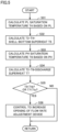
- Fig. 2 is a flowchart for controller 100 to control flow rate adjustment device LEV2 for adjusting the amount of returned oil based on compressor differential pressure Pd of compressor 10.
- controller 100 In controller 100, CPU 102 reads, in step S1, the above-described valve-opening calculation formula from memory 104, during operation of refrigeration cycle apparatus 1. Controller 100 calculates, in step S2, compressor differential pressure Pd, based on a value of detected pressure PL on the suction side of compressor 10 that is input from pressure sensor 131, and a value of detected pressure PH on the discharge side of compressor 10 that is input from pressure sensor 132.
- Controller 100 performs, in step S3, calculation of the valve opening of flow rate adjustment device LEV2, by using the above-described valve opening calculation formula, from compressor differential pressure Pd calculated in step S2. Controller 100 performs, in step S4, control for adjusting the valve opening of flow rate adjustment device LEV2, such that the valve opening is set to the valve opening calculated in step S3.
- valve-opening adjustment control is performed for flow rate adjustment device LEV2, based on the suction-discharge pressure difference of compressor 10, so that refrigeration oil can be returned from oil return path F2 to compressor 10, without excess or shortage of the oil.
- failure of compressor 10 due to shortage of the amount of refrigeration oil returned to compressor 10 can be prevented.
- deterioration of the refrigeration capacity due to an excessive amount of refrigeration oil and refrigerant returned to compressor 10 can be prevented.
- the valve-opening adjustment control is performed for flow rate adjustment device LEV2 based on the suction-discharge pressure difference of compressor 10, to thereby enable stabilization of the state of oil returned to compressor 10.
- valve-opening calculation formula a calculation formula may be used that can be used to calculate the valve opening to change the amount of refrigeration oil necessary for maintaining a normal operating state, depending on the operating frequency (operating rotational speed) of compressor 10 in addition to compressor differential pressure Pd.
- the reason why the valve opening of flow rate adjustment device LEV2 is calculated based on the operating frequency of compressor 10 in addition to compressor differential pressure Pd is as follows: if the operating frequency of compressor 10 is changed, the amount of refrigeration oil that has to be returned to compressor 10 is changed, in response to a change of the amount of refrigeration oil taken away from compressor 10.
- the valve opening that causes the amount of refrigeration oil returned to compressor 10 during operation of refrigeration cycle apparatus 1 to be set to the oil amount necessary for maintaining a normal operating state may be determined by means of a data table that is stored in memory 104 in advance and indicates a relation between compressor differential pressure Pd and the valve opening that causes the oil amount to be set to the oil amount necessary for maintaining a normal operating state, and the data table may be used to determine the valve opening associated with compressor differential pressure Pd determined in the above-described manner.
- a data table by which the valve opening of flow rate adjustment device LEV2 can be determined based on the operating frequency of compressor 10 in addition to compressor differential pressure Pd, may be used.
- Compressor 10 is provided with the aforementioned refrigeration oil reservoir in which refrigeration oil is stored.
- the refrigeration oil reservoir may be provided with a liquid level sensor that detects the liquid level of refrigeration oil. If the refrigeration oil reservoir is provided with the liquid level sensor, a detection signal indicating a value of the liquid level detected by the liquid level sensor is input to controller 100.
- Controller 100 may control the valve opening of flow rate adjustment device LEV2, such that the liquid level of refrigeration oil detected by the liquid level sensor provided at the refrigeration oil reservoir of compressor 10 has a certain value. For example, controller 100 may control the valve opening of flow rate adjustment device LEV2, such that a value of the liquid level detected by the liquid level sensor does not become lower than a certain liquid level.
- Oil separator 20 may be provided with a liquid level sensor that detects the liquid level of refrigeration oil. If oil separator 20 is provided with the liquid level sensor that detects the liquid level of refrigeration oil, a detection signal indicating a value of the liquid level detected by the liquid level sensor is input to controller 100. Controller 100 may control the valve opening of flow rate adjustment device LEV2, such that the liquid level of refrigeration oil detected by the liquid level sensor provided at oil separator 20 has a certain value. For example, controller 100 may control the valve opening of flow rate adjustment device LEV2, such that a value of the liquid level detected by the liquid level sensor does not become higher than a certain liquid level.
- controller 100 performs, in the manner as described below, control for opening flow rate adjustment device LEV2 to make compressor differential pressure Pd smaller than a threshold value when compressor 10 is activated.
- Fig. 3 is a flowchart of control for controller 100 to open flow rate adjustment device LEV2 for adjusting compressor differential pressure Pd when compressor 10 is activated.
- controller 100 determines whether or not compressor 10 is activated now. When determining that the compressor is not activated now in step S11, controller 100 makes a return. When determining that the compressor is activated now in step S11, controller 100 calculates, in step S12, compressor differential pressure Pd, based on a value of detected suction-side pressure PL of compressor 10 that is input from pressure sensor 131 and a value of detected discharge-side pressure PH of compressor 10 that is input from pressure sensor 132.
- Controller 100 determines, in step S13, whether or not compressor differential pressure Pd calculated in step S12 is more than or equal to a threshold value Pt of the differential pressure.
- controller 100 When determining in step S13 that compressor differential pressure Pd is not more than or equal to threshold value Pt, controller 100 makes a return. In contrast, when determining in step S13 that compressor differential pressure Pd is more than or equal to threshold value Pt, controller 100 performs, in step S 14, control for opening flow rate adjustment device LEV2, such that compressor differential pressure Pd is made less than threshold value Pt. Threshold value Pt is set to at least a value that does not cause deterioration of the activation capability of compressor 10. Such control of flow rate adjustment device LEV2 by controller 100 may be stopped at the time when compressor differential pressure Pd becomes lower than threshold value Pt even slightly, or when compressor differential pressure Pd becomes zero.
- control can be performed for opening flow rate adjustment device LEV2 to make the pressure difference between suction-side pressure PL and discharge-side pressure PH smaller than a reference value, to thereby improve the activation capability of compressor 10.
- controller 100 determines whether or not oil return path F2 is clogged, based on a value of detected temperature T1 of pipe 91 located upstream of flow rate adjustment device LEV2, and a value of detected temperature T2 of pipe 80 located on the discharge side of compressor 10, and performs various types of control for preventing failure of compressor 10, in the following way.
- oil return path F2 If oil return path F2 is not clogged and refrigeration oil flows therein in a normal manner, there is no shortage in the amount of returned oil, so that the heat amount of refrigeration oil flowing in oil return path F2 makes it less likely that temperature T1 of pipe 91 is lowered. In contrast, if oil return path F2 is clogged and refrigeration oil does not flow therein in a normal manner, shortage in the amount of returned oil results in reduction of the heat amount of refrigeration oil flowing in oil return path F2, relative to the case where no clogging occurs and refrigeration oil flows in a normal manner, so that temperature T1 of pipe 91 is likely to be lowered.
- controller 100 performs control in the following manner.
- Fig. 4 is a flowchart for controller 100 to perform control when oil return path F2 is clogged.
- Controller 100 calculates, in step S21, a temperature difference Td between temperature T2 and temperature T1, based on temperature T2 detected by temperature sensor 122 and temperature T1 detected by temperature sensor 121. Controller 100 determines, in step S22, whether or not temperature difference Td calculated in step S21 is more than or equal to a threshold value Tta for the temperature difference. Threshold value Tta is set to a value of temperature difference Td that may be generated upon occurrence of such clogging that may at least result in malfunction of compressor 10.
- controller 100 When determining in step S22 that temperature difference Td is not more than or equal to threshold value Tta, controller 100 makes a return. In contrast, when determining in step S22 that temperature difference Td is more than or equal to threshold value Tta, controller 100 determines that oil return path F2 is clogged and performs control for making a clogging alarm that indicates occurrence of the clogging.
- a clogging alarm is made by both a display and an alarm device that are connected to controller 100, or by at least one of them.
- the display can display the alarm.
- the alarm device can output an alarm sound.
- controller 100 After performing control for making the clogging alarm, controller 100 performs control to stop compressor 10.
- Controller 100 may be configured to perform the aforementioned control to make the clogging alarm, but not to perform the aforementioned control to stop compressor 10. This is for the reason that, in response to the clogging alarm, a person in charge can determine the situation to address the clogging by taking any of various measures such as stopping of compressor 10.
- controller 100 may be configured to perform the aforementioned control to stop compressor 10, but not to perform the aforementioned control to make the clogging alarm. This is for the reason that, if at least compressor 10 is stopped, compressor 10 can be prevented from failing due to clogging of oil return path F2.
- controller 100 may be configured to simultaneously perform the aforementioned control to make the alarm and the aforementioned control to stop compressor 10. Controller 100 may also be configured to perform the aforementioned control to make the alarm and thereafter perform the aforementioned control to stop compressor 10. Controller 100 may also be configured to perform the aforementioned control to stop compressor 10 and thereafter perform the aforementioned control to make the alarm.
- Controller 100 may also be configured to perform control to reduce the operating frequency of compressor 10, before performing the aforementioned control to stop compressor 10. Controller 100 may also be configured to increase the opening of flow rate adjustment device LEV2 provided at oil return path F2, before performing the aforementioned control to stop compressor 10.
- Temperature sensor 121 provided at oil return path F2 for detecting temperature T1 of refrigeration oil returned from oil separator 20 may be provided at a position for detecting the temperature of pipe 92 located downstream of flow rate adjustment device LEV2.
- Liquid back refers to a phenomenon in which refrigerant is not completely evaporated in evaporator 60 and liquid refrigerant flows back to compressor 10.
- controller 100 When such liquid back occurs, controller 100 performs control to increase the opening of flow rate adjustment device LEV2 provided in oil return path F2, and thereby promote return of refrigeration oil from oil separator 20 to compressor 10 and accordingly prevent exhaustion of refrigeration oil. Specifically, controller 100 performs the following control to address liquid back.
- Fig. 5 is a flowchart for controller 100 to control the opening of flow rate adjustment device LEV2 when liquid back occurs.
- step S31 based on a detected value of pressure PL on the suction side of compressor 10 detected by pressure sensor 131, controller 100 calculates a PL saturation temperature T4 corresponding to the detected value of pressure PL.
- step S33 based on a detected value of pressure PH on the discharge side of compressor 10 detected by pressure sensor 132, controller 100 calculates a PH saturation temperature T6 corresponding to the detected value of pressure PH.
- controller 100 determines whether or not at least one of shell-bottom superheat T5 calculated in step S32 and discharge superheat T7 calculated in step S34 is lower than an associated threshold value Ttb of shell-bottom superheat T5/an associated threshold value Ttc of discharge superheat T7.
- Threshold value Ttb is set to a predetermined value at which shell-bottom superheat T5 is sure to cause liquid back.
- Threshold value Ttc is set to a predetermined value at which discharge superheat T7 is sure to cause liquid back.
- controller 100 makes a return.
- controller 100 determines, in step S36, that liquid back occurs and performs control to increase the valve opening of flow rate adjustment device LEV2.
- Controller 100 may use the temperature of any one of shell-bottom superheat T5 and discharge superheat T7 and, when the detected value of the temperature is lower than the associated threshold value, controller 100 may determine that liquid back occurs, or when the detected values of respective temperatures of both the superheats are lower than respective associated threshold values, controller 100 may determine that liquid back occurs.
- controller 100 may use a parameter other than shell-bottom superheat T5 and discharge superheat T7, for determining whether or not liquid back occurs.
- the liquid level of refrigeration oil stored in compressor 10 may be detected and, when the detected liquid level becomes lower than a reference level, controller 100 may determine that liquid back occurs.
- the temperature itself of refrigeration oil stored in compressor 10 may be detected and, when the detected temperature becomes lower than a reference value, controller 100 may determine that liquid back occurs.
- controller 100 can determine that liquid back occurs. When determining that liquid back occurs, controller 100 can perform control to increase the valve opening of flow rate adjustment device LEV2 and thereby promote return of refrigeration oil from oil separator 20 back to compressor 10 upon occurrence of liquid back, and accordingly prevent exhaustion of refrigeration oil.
- Fig. 6 is an overall configuration diagram of a refrigeration cycle apparatus 1A according to Embodiment 2.
- Refrigeration cycle apparatus 1A in Fig. 6 differs from refrigeration cycle apparatus 1 in Fig. 1 in that a cold source unit 2A is provided with oil return path F2 between the outlet side of oil separator 20 and the suction side of compressor 10 that includes a first oil return path F21 in which refrigeration oil is returned through flow rate adjustment device LEV2, and a second oil return path F22 which is disposed in parallel with the first oil return path and in which refrigeration oil is returned through electromagnetic valve 40.
- oil can be returned from oil separator 20 to compressor 10 through flow rate adjustment device LEV2 and also through electromagnetic valve 40.
- refrigeration cycle apparatus 1A in Fig. 6 differs from refrigeration cycle apparatus 1 in Fig. 1 in that a liquid level sensor 141 for refrigeration oil is provided at the refrigeration oil reservoir of compressor 10, like the one as described in connection with Embodiment 1.
- Liquid level sensor 141 detects a liquid level L of refrigeration oil in the refrigeration oil reservoir of compressor 10, and outputs a detection signal indicating a value of the detected level to controller 100.
- electromagnetic valve 40 is controlled into one of a fully opened state and a fully closed state.
- opened state of electromagnetic valve 40 refers to the “fully opened state”
- closed state of electromagnetic valve 40 refers to the “fully closed state.”
- controller 100 controls electromagnetic valve 40 such that its valve opening is in the closed state.
- controller 100 controls electromagnetic valve 40 such that its valve opening is in the opened state.
- Fig. 7 is a flowchart for controller 100 to control electromagnetic valve 40 into the opened state, in response to shortage of the amount of oil returned to compressor 10 regardless of the fact that the valve opening of flow rate adjustment device LEV2 is in the fully opened state.
- controller 100 performs a process like the one shown in Fig. 2 in a similar manner to Embodiment 1, to control flow rate adjustment device LEV2 for adjusting the amount of returned oil based on compressor differential pressure Pd of compressor 10. Further, controller 100 performs the following control based on monitoring of the valve opening of flow rate adjustment device LEV2 and a detected value of liquid level L detected by liquid level sensor 141 for refrigeration oil provided at compressor 10.
- step S41 controller 100 determines whether or not the current valve opening of flow rate adjustment device LEV2 is the maximum opening. Controller 100 makes a return when determining, in step S41, that the valve opening is not the maximum opening.
- controller 100 determines, in step S42, whether or not liquid level L of refrigeration oil of compressor 10 detected by liquid level sensor 141 becomes lower than the level of a threshold value Lt that is necessary for maintaining a normal operating state of compressor 10. Controller 100 makes a return when determining, in step S42, that liquid level L of refrigeration oil of compressor 10 does not become lower than the level of threshold value Lt.
- controller 100 When determining, in step S42, that liquid level L of refrigeration oil in compressor 10 becomes lower than the level of threshold value Lt, controller 100 sends a control signal to electromagnetic valve 40 to control electromagnetic valve 40 into the opened state.
- control of electromagnetic valve 40 by controller 100 may be performed, after S43, to set electromagnetic valve 40 into the closed state after a certain time has elapsed, based on data set in a data table stored in advance in memory 104, or set electromagnetic valve 40 into the closed state immediately after S43.
- Controller 100 performs such oil return control through the electromagnetic valve, when the ability to supply oil back to compressor 10 through flow rate adjustment LEV2 is not sufficient, to thereby enable oil to be returned to compressor 10 through electromagnetic valve 40. In this way, occurrences of shortage of the amount of returned oil can be reduced. The stability of the operation of compressor 10 can thus be ensured.
- Controller 100 may store, in advance in memory 104, a data table indicating a relation between compressor differential pressure Pd and the amount of returned refrigeration oil necessary for maintaining a normal operation of compressor 10 during operation of refrigeration cycle apparatus 1, and also store, in advance in memory 104, a data table indicating a relation between the valve opening of flow rate adjustment device LEV2 and the amount of refrigeration oil returned to compressor 10. Controller 100 may use these data tables to determine whether or not the amount of returned refrigeration oil necessary for maintaining a normal operating state of compressor 10 for compressor differential pressure Pd is still insufficient even when the valve opening of flow rate adjustment device LEV2 is set in the maximum state and, when it is insufficient, controller 100 may send a control signal to electromagnetic valve 40 to control electromagnetic valve 40 into the opened state from the closed state. As such a data table, a data table indicating a relation of compressor differential pressure Pd and the operating frequency of compressor 10 to the amount of returned refrigeration oil may also be used.
- activation-time electromagnetic valve control that controls electromagnetic valve 40 for adjusting compressor differential pressure Pd when compressor 10 is activated.
- control to open flow rate adjustment device LEV2 for adjusting compressor differential pressure Pd as described in connection with Embodiment 1 is not performed.
- controller 100 performs, in the manner as described below, control for changing electromagnetic valve 40 from the closed state to the opened state to make compressor differential pressure Pd smaller than a reference value when compressor 10 is activated.
- Fig. 8 is a flowchart for controller 100 to control electromagnetic valve 40 for adjusting compressor differential pressure Pd when compressor 10 is activated.
- step S51 controller 100 determines whether or not compressor 10 is activated now. When determining that the compressor is not activated now in step S51, controller 100 makes a return. When determining that the compressor is activated now in step S51, controller 100 calculates, in step S52, compressor differential pressure Pd, based on a value of detected suction-side pressure PL of compressor 10 that is input from pressure sensor 131 and a value of detected discharge-side pressure PH of compressor 10 that is input from pressure sensor 132.
- Controller 100 determines, in step S53, whether or not compressor differential pressure Pd calculated in step S52 is more than or equal to a threshold value Pt of the differential pressure.
- controller 100 When determining in step S53 that compressor differential pressure Pd is not more than or equal to threshold value Pt, controller 100 makes a return. In contrast, when determining in step S53 that compressor differential pressure Pd is more than or equal to threshold value Pt, controller 100 performs, in step S54, control for setting electromagnetic valve 40 in the opened state, such that compressor differential pressure Pd is made less than threshold value Pt. While such control is performed, flow rate adjustment device LEV2 is kept in the closed state. Threshold value Pt is set to at least a value that does not cause deterioration of the activation capability of compressor 10. Such control of electromagnetic valve 40 by controller 100 may be stopped at the time when compressor differential pressure Pd becomes lower than threshold value Pt even slightly, or when compressor differential pressure Pd becomes zero.
- control can be performed for setting electromagnetic valve 40 in the opened state to make the pressure difference between suction-side pressure PL and discharge-side pressure PH smaller than a reference value, to thereby improve the activation capability of compressor 10.
- controller 100 may perform control to open both flow rate adjustment device LEV2 and electromagnetic valve 40, for making compressor differential pressure Pd between suction-side pressure PL and discharge-side pressure PH smaller than differential-pressure threshold value Pt.
- controller 100 may perform control to open one of flow rate adjustment device LEV2 and electromagnetic valve 40 that is selected based on the magnitude of compressor differential pressure Pd detected when compressor 10 is activated, for making compressor differential pressure Pd between suction-side pressure PL and discharge-side pressure PH smaller than differential-pressure threshold value Pt. For example, controller 100 separately specifies a first pressure difference and a second pressure difference larger than the first pressure difference, each as a pressure difference that is more than or equal to threshold value Pt of the differential pressure that may be detected when compressor 10 is activated.
- controller 100 When compressor differential pressure Pd detected when compressor 10 is activated is more than or equal to the first pressure difference and less than the second pressure difference, controller 100 performs control to open one of flow rate adjustment device LEV2 and electromagnetic valve 40 that is lower in terms of the pressure adjusting ability. When the pressure difference detected when compressor 10 is activated is more than or equal to the second pressure difference, controller 100 performs control to open one of flow rate adjustment device LEV2 and electromagnetic valve 40 that is higher in the pressure adjustment ability.
- controller 100 When such liquid back occurs, controller 100 performs control to switch electromagnetic valve 40 provided in oil return path F2 from the closed state to the opened state, and thereby promote return of refrigeration oil from oil separator 20 to compressor 10 and accordingly prevent exhaustion of refrigeration oil. Specifically, controller 100 performs the following control to address liquid back.
- Fig. 9 is a flowchart for controller 100 to control electromagnetic valve 40 into the opened state when liquid back occurs.
- step S61 based on a detected value of pressure PL on the suction side of compressor 10 detected by pressure sensor 131, controller 100 calculates PL saturation temperature T4 corresponding to the detected value of pressure PL.
- step S63 based on a detected value of pressure PH on the discharge side of compressor 10 detected by pressure sensor 132, controller 100 calculates PH saturation temperature T6 corresponding to the detected value of pressure PH.
- controller 100 determines whether or not at least one of shell-bottom superheat T5 calculated in step S62 and discharge superheat T7 calculated in step S64 is lower than associated threshold value Ttb of shell-bottom superheat T5/associated threshold value Ttc of discharge superheat T7.
- Threshold value Ttb is set to a predetermined value at which shell-bottom superheat T5 is sure to cause liquid back.
- Threshold value Ttc is set to a predetermined value at which discharge superheat T7 is sure to cause liquid back.
- controller 100 makes a return.
- controller 100 determines, in step S66, that liquid back occurs and performs control to switch electromagnetic valve 40 from the closed state to the opened state.
- controller 100 may set electromagnetic valve 40 in the closed state after a certain time has elapsed, based on data that is set in a data table stored in advance in memory 104, after S66 is performed, or may set electromagnetic valve 40 in the closed state immediately after S66 is performed.
- Controller 100 may use the temperature of any one of shell-bottom superheat T5 and discharge superheat T7 and, when the detected value of the temperature is lower than the associated threshold value, controller 100 may determine that liquid back occurs, or when the detected values of respective temperatures of both the superheats are lower than respective associated threshold values, controller 100 may determine that liquid back occurs.
- controller 100 may use a parameter other than shell-bottom superheat T5 and discharge superheat T7, for determining whether or not liquid back occurs. For example, the liquid level of refrigeration oil stored in compressor 10 may be detected and, when the detected liquid level becomes lower than a threshold value, controller 100 may determine that liquid back occurs. The temperature itself of refrigeration oil stored in compressor 10 may be detected and, when the detected temperature becomes lower than a threshold value, controller 100 may determine that liquid back occurs.
- Cold source unit 2 for a refrigeration cycle apparatus to be connected to load apparatus 3.
- Cold source unit 2 includes: refrigerant flow path F 1 to be connected to load apparatus 3 and thereby form a circulation flow path in which refrigerant circulates; compressor 10 disposed in refrigerant flow path F1; oil separator 20 disposed on a discharge side of compressor 10 in refrigerant flow path F1; oil return path F2 to return refrigeration oil from oil separator 20 to compressor 10; flow rate adjustment device LEV2 disposed in oil return path F2 and configured to adjust a flow rate of fluid flowing in oil return path F2; pressure sensor 131 disposed in oil return path F2 to detect pressure PL on a suction side of compressor 10; pressure sensor 132 disposed in oil return path F2 to detect pressure PH on the discharge side of compressor 10; and a controller to control the opening of flow rate adjustment device LEV2 based on the pressure detected by pressure sensor 131 and the pressure detected by pressure sensor 132.
- the opening of flow rate adjustment device LEV2 is controlled, based on pressure PL on the suction side of compressor 10 that is detected by pressure sensor 131 and pressure PH detected by pressure sensor 132, which enables the state of oil returned to compressor 10 to be stabilized.
- controller 100 when compressor 10 is activated, controller 100 performs control to open flow rate adjustment device LEV2, based on a pressure difference between pressure PL detected by pressure sensor 131 and pressure PH detected by pressure sensor 132.
- This configuration enables, when compressor 10 is activated, the pressure difference between suction-side pressure PL and discharge-side pressure PH to be smaller than a reference value, and thereby enables the activation capability of compressor 10 to be improved.
- the cold source unit further includes temperature sensor 121 disposed in oil return path F2 to detect temperature T1 of oil return path F2, controller 100 determines whether or not oil return path F2 is clogged, based on the temperature detected by temperature sensor 121. More specifically, based on the temperature difference between temperature T1 of pipe 91 located upstream of flow rate adjustment device LEV2 and temperature T2 of pipe 80 located on the discharge side of compressor 10, it is determined whether or not oil return path F2 is clogged. With this configuration, the temperature of oil return path F2 is detected and whether or not oil return path F2 is clogged is determined based on the detected temperature, which ensures that exhaustion of refrigeration oil used in compressor 10 is recognized.
- controller 100 performs control to increase the opening of flow rate adjustment device LEV2, in response to occurrence of liquid back that is returning of liquid refrigerant from oil return path F2 to compressor 10. This configuration enables, when liquid back occurs, returning of refrigeration oil from oil separator 20 to compressor 10 to be promoted, to thereby prevent exhaustion of refrigeration oil.
- the cold source unit further includes electromagnetic valve 40 to be opened or closed for making a flow rate of fluid flowing in oil return path F2 adjustable, where electromagnetic valve 40 is disposed in oil return path F2 and arranged in parallel with flow rate adjustment device LEV2, and controller 100 controls electromagnetic valve 40 when refrigeration oil returned to compressor 10 is insufficient under a condition that flow rate adjustment device LEV2 is opened based on pressure PL on the suction side of compressor 10 detected by pressure sensor 131 and pressure PH detected by pressure sensor 132.
- This configuration enables oil to be returned to compressor 10 through electromagnetic valve 40, and thereby enables reduction of occurrences of shortage in the amount of returned oil. Accordingly, the stability of the operation of compressor 10 can be ensured.
- the controller when the compressor is activated, performs control to open electromagnetic valve 40, based on a pressure difference between pressure PL detected by pressure sensor 131 and pressure PH detected by pressure sensor 132.
- This configuration enables, when compressor 10 is activated, reduction of the pressure difference between suction-side pressure PL and discharge-side pressure PH, and thereby enables the activation capability of compressor 10 to be improved.
- controller 100 performs control to open electromagnetic valve 40, in response to occurrence of liquid back that is returning of liquid refrigerant from oil return path F2 to compressor 10. This configuration enables, when liquid back occurs, returning of refrigeration oil from oil separator 20 to compressor 10 to be promoted, to thereby prevent exhaustion of refrigeration oil.
- the present disclosure according to another aspect relates to refrigeration cycle apparatus 1 including: cold source unit 2 according to any one the foregoing; and load apparatus 3.
- the refrigeration cycle apparatus controls the opening of flow rate adjustment device LEV2 based on pressure PL on the suction side of compressor 10 detected by pressure sensor 131 and pressure PH detected by pressure sensor 132, and therefore enables the state of oil returned to compressor 10 to be stabilized.
- 1, 1A refrigeration cycle apparatus 1, 2A cold source unit; 3 load apparatus; 10 compressor; 20 oil separator; 30 gas cooler; F2 oil return path; LEV2 flow rate adjustment device; 131, 132 pressure sensor; 100 controller; 121, 122 temperature sensor
Landscapes
- Engineering & Computer Science (AREA)
- Physics & Mathematics (AREA)
- Mechanical Engineering (AREA)
- Thermal Sciences (AREA)
- General Engineering & Computer Science (AREA)
- Air Conditioning Control Device (AREA)
Applications Claiming Priority (1)
| Application Number | Priority Date | Filing Date | Title |
|---|---|---|---|
| PCT/JP2020/047521 WO2022130637A1 (fr) | 2020-12-18 | 2020-12-18 | Ensemble source de chaleur froide et dispositif à cycle frigorifique |
Publications (2)
| Publication Number | Publication Date |
|---|---|
| EP4265980A1 true EP4265980A1 (fr) | 2023-10-25 |
| EP4265980A4 EP4265980A4 (fr) | 2024-05-08 |
Family
ID=82059301
Family Applications (1)
| Application Number | Title | Priority Date | Filing Date |
|---|---|---|---|
| EP20966023.2A Withdrawn EP4265980A4 (fr) | 2020-12-18 | 2020-12-18 | Ensemble source de chaleur froide et dispositif à cycle frigorifique |
Country Status (3)
| Country | Link |
|---|---|
| EP (1) | EP4265980A4 (fr) |
| JP (1) | JPWO2022130637A1 (fr) |
| WO (1) | WO2022130637A1 (fr) |
Families Citing this family (4)
| Publication number | Priority date | Publication date | Assignee | Title |
|---|---|---|---|---|
| WO2024111097A1 (fr) * | 2022-11-24 | 2024-05-30 | 三菱電機株式会社 | Dispositif à cycle frigorifique |
| WO2024116246A1 (fr) * | 2022-11-28 | 2024-06-06 | 三菱電機株式会社 | Dispositif à cycle de réfrigération |
| WO2024122029A1 (fr) * | 2022-12-08 | 2024-06-13 | 三菱電機株式会社 | Appareil à cycle de réfrigération |
| WO2025109720A1 (fr) * | 2023-11-22 | 2025-05-30 | 三菱電機株式会社 | Dispositif à cycle frigorifique |
Family Cites Families (12)
| Publication number | Priority date | Publication date | Assignee | Title |
|---|---|---|---|---|
| JPH0725574Y2 (ja) * | 1989-11-17 | 1995-06-07 | 三菱重工業株式会社 | 冷媒回収装置 |
| JPH0626714A (ja) * | 1992-07-08 | 1994-02-04 | Mitsubishi Heavy Ind Ltd | 空気調和機の冷媒回路 |
| JPH0674579A (ja) * | 1992-08-26 | 1994-03-15 | Daikin Ind Ltd | 冷凍装置 |
| JP3468174B2 (ja) * | 1999-09-14 | 2003-11-17 | 三菱電機株式会社 | 冷凍空調サイクル装置 |
| JP2003202146A (ja) * | 2002-01-10 | 2003-07-18 | Sanyo Electric Co Ltd | 空気調和装置 |
| JP5418253B2 (ja) * | 2010-01-28 | 2014-02-19 | パナソニック株式会社 | 冷凍サイクル装置 |
| JP2011208860A (ja) * | 2010-03-29 | 2011-10-20 | Hitachi Appliances Inc | 空気調和機 |
| JP5921425B2 (ja) * | 2012-12-12 | 2016-05-24 | ヤンマー株式会社 | 空調機 |
| CN105579787B (zh) * | 2013-09-24 | 2018-01-05 | 三菱电机株式会社 | 冷冻循环装置 |
| CN105928251B (zh) * | 2016-05-06 | 2018-05-08 | 宁波工程学院 | 热泵 |
| JP2018059663A (ja) * | 2016-10-05 | 2018-04-12 | 三菱重工サーマルシステムズ株式会社 | 制御装置、冷媒回路システム、制御方法及びプログラム |
| JP2020051662A (ja) * | 2018-09-26 | 2020-04-02 | 日立ジョンソンコントロールズ空調株式会社 | 冷凍空調装置及びこれに用いる密閉型電動圧縮機 |
-
2020
- 2020-12-18 EP EP20966023.2A patent/EP4265980A4/fr not_active Withdrawn
- 2020-12-18 WO PCT/JP2020/047521 patent/WO2022130637A1/fr not_active Ceased
- 2020-12-18 JP JP2022569678A patent/JPWO2022130637A1/ja active Pending
Also Published As
| Publication number | Publication date |
|---|---|
| WO2022130637A1 (fr) | 2022-06-23 |
| EP4265980A4 (fr) | 2024-05-08 |
| JPWO2022130637A1 (fr) | 2022-06-23 |
Similar Documents
| Publication | Publication Date | Title |
|---|---|---|
| EP4265980A1 (fr) | Ensemble source de chaleur froide et dispositif à cycle frigorifique | |
| CN101821507B (zh) | 用于监测压缩机过热的系统和方法 | |
| EP1706684B1 (fr) | Procede pour diagnostiquer une perte de charge refrigerante dans un systeme refrigerant | |
| US7775057B2 (en) | Operational limit to avoid liquid refrigerant carryover | |
| CN107990609B (zh) | 电子膨胀阀的控制方法及冷媒循环系统 | |
| KR101602741B1 (ko) | 항온액 순환 장치 및 그 운전 방법 | |
| EP3115715A1 (fr) | Système à cycle de réfrigération | |
| US20120117995A1 (en) | Energy Saving Device And Method For Cooling And Heating Apparatus | |
| CN100406820C (zh) | 冷冻循环系统及其控制方法 | |
| CN112303972B (zh) | 电子膨胀阀控制方法、系统及制冷系统 | |
| EP3875869B1 (fr) | Système de pompe à chaleur et son procédé de commande | |
| JP7282258B2 (ja) | 室外ユニットおよび冷凍サイクル装置 | |
| JPH04240355A (ja) | 空気調和装置における電子膨脹弁の制御方法 | |
| JP2001311567A (ja) | 冷凍装置およびそれを用いた環境試験装置 | |
| CN115325669A (zh) | 元件温度控制方法、装置、空调器及存储介质 | |
| CN116772381B (zh) | 空调电子膨胀阀开度的调节方法和装置 | |
| KR100565995B1 (ko) | 실내기 설치 위치에 따른 멀티형 에어컨의 운전 방법 | |
| US20220146165A1 (en) | Air conditioning apparatus | |
| JP2008249240A (ja) | コンデンシングユニット及びそれを備えた冷凍装置 | |
| CN110173936A (zh) | 用于控制蒸发器内的液体水平的方法及其系统 | |
| JPH07294073A (ja) | 冷凍装置 | |
| JP6785381B2 (ja) | 冷凍サイクル装置 | |
| JP2008202868A (ja) | 空気調和機 | |
| JP7342269B2 (ja) | 冷熱源ユニット、および冷凍サイクル装置 | |
| JP2001091064A (ja) | 冷凍装置 |
Legal Events
| Date | Code | Title | Description |
|---|---|---|---|
| STAA | Information on the status of an ep patent application or granted ep patent |
Free format text: STATUS: THE INTERNATIONAL PUBLICATION HAS BEEN MADE |
|
| PUAI | Public reference made under article 153(3) epc to a published international application that has entered the european phase |
Free format text: ORIGINAL CODE: 0009012 |
|
| STAA | Information on the status of an ep patent application or granted ep patent |
Free format text: STATUS: REQUEST FOR EXAMINATION WAS MADE |
|
| 17P | Request for examination filed |
Effective date: 20230519 |
|
| AK | Designated contracting states |
Kind code of ref document: A1 Designated state(s): AL AT BE BG CH CY CZ DE DK EE ES FI FR GB GR HR HU IE IS IT LI LT LU LV MC MK MT NL NO PL PT RO RS SE SI SK SM TR |
|
| REG | Reference to a national code |
Ref country code: DE Ref legal event code: R079 Free format text: PREVIOUS MAIN CLASS: F25B0001000000 Ipc: F25B0031000000 |
|
| RIC1 | Information provided on ipc code assigned before grant |
Ipc: F25B 31/00 20060101AFI20240111BHEP |
|
| DAV | Request for validation of the european patent (deleted) | ||
| DAX | Request for extension of the european patent (deleted) | ||
| A4 | Supplementary search report drawn up and despatched |
Effective date: 20240409 |
|
| RIC1 | Information provided on ipc code assigned before grant |
Ipc: F25B 31/00 20060101AFI20240403BHEP |
|
| STAA | Information on the status of an ep patent application or granted ep patent |
Free format text: STATUS: THE APPLICATION HAS BEEN WITHDRAWN |
|
| 18W | Application withdrawn |
Effective date: 20240709 |