EP4266021A1 - Ensemble capteur et dispositif de soupape - Google Patents
Ensemble capteur et dispositif de soupape Download PDFInfo
- Publication number
- EP4266021A1 EP4266021A1 EP21905737.9A EP21905737A EP4266021A1 EP 4266021 A1 EP4266021 A1 EP 4266021A1 EP 21905737 A EP21905737 A EP 21905737A EP 4266021 A1 EP4266021 A1 EP 4266021A1
- Authority
- EP
- European Patent Office
- Prior art keywords
- pressure sensing
- sensing unit
- face
- section
- sealing
- Prior art date
- Legal status (The legal status is an assumption and is not a legal conclusion. Google has not performed a legal analysis and makes no representation as to the accuracy of the status listed.)
- Pending
Links
Images




Classifications
-
- G—PHYSICS
- G01—MEASURING; TESTING
- G01L—MEASURING FORCE, STRESS, TORQUE, WORK, MECHANICAL POWER, MECHANICAL EFFICIENCY, OR FLUID PRESSURE
- G01L19/00—Details of, or accessories for, apparatus for measuring steady or quasi-steady pressure of a fluent medium insofar as such details or accessories are not special to particular types of pressure gauges
- G01L19/0092—Pressure sensor associated with other sensors, e.g. for measuring acceleration or temperature
-
- G—PHYSICS
- G01—MEASURING; TESTING
- G01D—MEASURING NOT SPECIALLY ADAPTED FOR A SPECIFIC VARIABLE; ARRANGEMENTS FOR MEASURING TWO OR MORE VARIABLES NOT COVERED IN A SINGLE OTHER SUBCLASS; TARIFF METERING APPARATUS; MEASURING OR TESTING NOT OTHERWISE PROVIDED FOR
- G01D21/00—Measuring or testing not otherwise provided for
- G01D21/02—Measuring two or more variables by means not covered by a single other subclass
-
- G—PHYSICS
- G01—MEASURING; TESTING
- G01K—MEASURING TEMPERATURE; MEASURING QUANTITY OF HEAT; THERMALLY-SENSITIVE ELEMENTS NOT OTHERWISE PROVIDED FOR
- G01K1/00—Details of thermometers not specially adapted for particular types of thermometer
- G01K1/08—Protective devices, e.g. casings
-
- G—PHYSICS
- G01—MEASURING; TESTING
- G01K—MEASURING TEMPERATURE; MEASURING QUANTITY OF HEAT; THERMALLY-SENSITIVE ELEMENTS NOT OTHERWISE PROVIDED FOR
- G01K1/00—Details of thermometers not specially adapted for particular types of thermometer
- G01K1/14—Supports; Fastening devices; Arrangements for mounting thermometers in particular locations
-
- G—PHYSICS
- G01—MEASURING; TESTING
- G01K—MEASURING TEMPERATURE; MEASURING QUANTITY OF HEAT; THERMALLY-SENSITIVE ELEMENTS NOT OTHERWISE PROVIDED FOR
- G01K13/00—Thermometers specially adapted for specific purposes
- G01K13/02—Thermometers specially adapted for specific purposes for measuring temperature of moving fluids or granular materials capable of flow
-
- G—PHYSICS
- G01—MEASURING; TESTING
- G01L—MEASURING FORCE, STRESS, TORQUE, WORK, MECHANICAL POWER, MECHANICAL EFFICIENCY, OR FLUID PRESSURE
- G01L19/00—Details of, or accessories for, apparatus for measuring steady or quasi-steady pressure of a fluent medium insofar as such details or accessories are not special to particular types of pressure gauges
- G01L19/0061—Electrical connection means
-
- G—PHYSICS
- G01—MEASURING; TESTING
- G01L—MEASURING FORCE, STRESS, TORQUE, WORK, MECHANICAL POWER, MECHANICAL EFFICIENCY, OR FLUID PRESSURE
- G01L19/00—Details of, or accessories for, apparatus for measuring steady or quasi-steady pressure of a fluent medium insofar as such details or accessories are not special to particular types of pressure gauges
- G01L19/0061—Electrical connection means
- G01L19/0084—Electrical connection means to the outside of the housing
-
- G—PHYSICS
- G01—MEASURING; TESTING
- G01L—MEASURING FORCE, STRESS, TORQUE, WORK, MECHANICAL POWER, MECHANICAL EFFICIENCY, OR FLUID PRESSURE
- G01L19/00—Details of, or accessories for, apparatus for measuring steady or quasi-steady pressure of a fluent medium insofar as such details or accessories are not special to particular types of pressure gauges
- G01L19/14—Housings
-
- G—PHYSICS
- G01—MEASURING; TESTING
- G01L—MEASURING FORCE, STRESS, TORQUE, WORK, MECHANICAL POWER, MECHANICAL EFFICIENCY, OR FLUID PRESSURE
- G01L19/00—Details of, or accessories for, apparatus for measuring steady or quasi-steady pressure of a fluent medium insofar as such details or accessories are not special to particular types of pressure gauges
- G01L19/14—Housings
- G01L19/142—Multiple part housings
-
- G—PHYSICS
- G01—MEASURING; TESTING
- G01L—MEASURING FORCE, STRESS, TORQUE, WORK, MECHANICAL POWER, MECHANICAL EFFICIENCY, OR FLUID PRESSURE
- G01L19/00—Details of, or accessories for, apparatus for measuring steady or quasi-steady pressure of a fluent medium insofar as such details or accessories are not special to particular types of pressure gauges
- G01L19/14—Housings
- G01L19/142—Multiple part housings
- G01L19/143—Two part housings
-
- G—PHYSICS
- G01—MEASURING; TESTING
- G01L—MEASURING FORCE, STRESS, TORQUE, WORK, MECHANICAL POWER, MECHANICAL EFFICIENCY, OR FLUID PRESSURE
- G01L9/00—Measuring steady of quasi-steady pressure of fluid or fluent solid material by electric or magnetic pressure-sensitive elements; Transmitting or indicating the displacement of mechanical pressure-sensitive elements, used to measure the steady or quasi-steady pressure of a fluid or fluent solid material, by electric or magnetic means
- G01L9/0041—Transmitting or indicating the displacement of flexible diaphragms
- G01L9/0051—Transmitting or indicating the displacement of flexible diaphragms using variations in ohmic resistance
- G01L9/0052—Transmitting or indicating the displacement of flexible diaphragms using variations in ohmic resistance of piezoresistive elements
-
- G—PHYSICS
- G01—MEASURING; TESTING
- G01D—MEASURING NOT SPECIALLY ADAPTED FOR A SPECIFIC VARIABLE; ARRANGEMENTS FOR MEASURING TWO OR MORE VARIABLES NOT COVERED IN A SINGLE OTHER SUBCLASS; TARIFF METERING APPARATUS; MEASURING OR TESTING NOT OTHERWISE PROVIDED FOR
- G01D3/00—Indicating or recording apparatus with provision for the special purposes referred to in the subgroups
- G01D3/028—Indicating or recording apparatus with provision for the special purposes referred to in the subgroups mitigating undesired influences, e.g. temperature, pressure
- G01D3/036—Indicating or recording apparatus with provision for the special purposes referred to in the subgroups mitigating undesired influences, e.g. temperature, pressure on measuring arrangements themselves
- G01D3/0365—Indicating or recording apparatus with provision for the special purposes referred to in the subgroups mitigating undesired influences, e.g. temperature, pressure on measuring arrangements themselves the undesired influence being measured using a separate sensor, which produces an influence related signal
Definitions
- the present application relates to the technical field of detection, and in particular to a sensor assembly and a valve device using the sensor assembly.
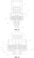
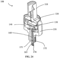
- a sensor assembly 100 in the related technology includes a pressure sensor element 130, an electronic circuit board 120, and a temperature sensor element 170.
- the sensor assembly 100 delivers fluid to the surface of the pressure sensor element 130 through the inlet opening 175 of an open liquid-tight channel, where the pressure sensor element 130 is used to sense pressure, and separates the temperature sensor 170 and the wire 160 from the fluid through a closed liquid-tight channel.
- the wire 160 extends in the slender tubular element 165 and is connected to the electronic circuit board 120 from the side through the hole of the base.
- the sensor assembly with this structure has too many parts, complicated assembly process and high production cost.
- An object of the present application is to provide a sensor assembly and a valve device with a simple structure and beneficial to reducing production costs.
- a valve device is further disclosed according to the present application, which includes a valve body and a sensor assembly, the valve body has a fluid channel, the detection channel is communicated with the fluid channel, the sensor assembly is the sensor assembly described above.
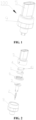
- a sensor assembly 100 provided by the present application includes a pressure sensing unit 1, a temperature sensing unit 2, a circuit unit 4, a connector 5, a sealing assembly 6 and a shell 9; the circuit unit 4 is located at one side of the pressure sensing unit 1, the sealing assembly 6 is located at the other side of the pressure sensing unit 1, in FIG. 1 to FIG. 16 ;
- the circuit unit 4 is located above the pressure sensing unit 1
- the sealing assembly 6 is located below the pressure sensing unit 1
- both the temperature sensing unit 2 and the pressure sensing unit 1 are electrically connected with the circuit unit 4
- the shell 9 and the connector 5 are fixedly connected to form an accommodating cavity 59
- the pressure sensing unit 1 and the circuit unit 4 are located in the accommodating cavity 59
- the sensor assembly 100 has a detection channel 101
- the temperature sensing unit 2 includes a temperature sensing part 21, at least part of the temperature sensing part 21 is located in the detection channel 101, the temperature sensing part 21 can convert the temperature in the detection channel 101 into an electrical signal, the temperature sensing part 21 can be a thermistor, and the type of the temperature sensing part 21 in the present application is not limited to this
- the pressure sensing unit 1 includes a pressure sensing part 20 and a body part 10, the body part 10 can be a ceramic substrate, and the pressure sensing part 20 is connected with the body part 10, the pressure sensing part 20 can convert the pressure in the detection
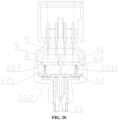
- the temperature sensing unit 2 further includes a conductive part 22 and a base 3, the conductive part 22 is electrically connected with the temperature sensing part 21 and the circuit unit 4, at least part of the conductive part 22 is connected with the base 3 by injection molding, at least part of the sealing part 62 is located between the base 3 and the pressure sensing unit 1.
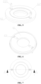
- the sealing assembly 6 includes a sealing part 62 and a metal framework 61, a main material of the sealing part 62 is rubber, the sealing part 62 is formed by injection molding with the metal framework 61 as an insert, and the metal framework 61 is of an annular shape.
- the alignment described here may include certain assembly error, the assembly error can be within 1mm, along a height direction of the sealing assembly 6, the sealing part 62 protrudes from the surface of the metal framework 61, and the pressure sensing unit 1 can contact the metal framework 61 after compressing the sealing part 62, the metal framework 61 presses the sealing part 62 against the bottom wall of the shell 9.
- the sealing assembly 6 has a first through hole 63, the temperature sensing part 21 is electrically connected with the circuit unit 4 through the conductive part 22, the conductive part 22 includes a first section 221, and, an end of the first section 221 passes through the first through hole 63 and is electrically connected with the circuit unit 4, a first flange part 23 is formed at the other end of the first section 221, an outer diameter of the first flange part 23 is larger than an aperture of the first through hole 63, and a labyrinth structure is formed between the sealing part 62 and the first section 221 of the conductive part 22, thus improving the sealing performance.
- the conductive part 22 further includes a second section 222 and a third section 223, the second section 222 is located between the first section 221 and the third section 223, and, the second section 222 is electrically connected to the first section 221 and the third section 223.
- the second section 222 is connected with the base 3 by injection molding, the second section 222 is in an elastic contact with and electrically connected with the first section 221; in this embodiment, an arc-shaped protrusion 220 is formed at one end of the second section 222 by bending or stamping, the arc-shaped protrusion 220 has certain elasticity, a planar part 230 is formed at the other end of the second section 222, the first flange part 23 of the first section 221 abuts against the arc-shaped protrusion 220 to form electrical connection, the third section 223 is fixed to the planar part 230 by welding, and a through hole can be defined in the planar part 230.
- the third section 223 is inserted into the through hole and fixed by welding.
- the planar part 230 extends into a corresponding area of the inner cavity of the base 3, so that an insertion end of the third section 223 can be straight and has a simple structure.
- the third section 223 is fixedly connected with the temperature sensing part 21, and one end of the third section 223 is connected with the temperature sensing part 21.
- part of the second section 222 is fixed with the base 3 by injection molding
- the base 3 has a second flange part 31 and a cylindrical part 32
- an outer edge size of the second flange part 31 is larger than an outer edge size of the cylindrical part 32
- the second flange part 31 is provided to protrude from the cylindrical part 32
- an upper end face of the second flange part 31 abuts against a lower end face of the sealing assembly 6
- a lower end face of the second flange part 31 is in contact with a bottom wall of the shell 9
- an upper end face of the sealing assembly 6 abuts against and is hermetically connected with a lower end face of the pressure sensing unit 1.
- the cylindrical part 32 has a notch part 321, a height of the notch part 321 is the same as a height of the temperature sensing part 21, the notch part 321 is communicated with an inner cavity of the base 3 (i.e., the detection channel 101), so that the working medium can enter the detection channel 101 through the notch part 321.
- the cylindrical part 32 forms a part of the side wall of the detection channel 101.
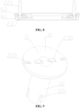
- the shell 9 has a first step part 91 and a second step part 92, the first step part 91 and the second step part 92 are located at the bottom wall of the shell 9, the first step part 91 has a first step surface 911, the second step part 92 has a second step surface 922, the first step surface 911 is closer to the pressure sensing unit 1 than the second step surface 922, the lower end face of the sealing part 62 is hermetically connected with the first step surface 911, the first flange part 23 of the first section 221 can abut against the first step surface 911 to limit the position, so as to prevent the first flange part 23 from crushing the arc-shaped protrusion 220; the second step part 92 has a mounting hole 923, the second flange part 31 abuts against the second step surface 922 for axial limit, and is laterally limited by a side wall of the second step part 92, the cylindrical part 32 of the base 3 is located in the mounting hole 923, at least part of the
- FIG. 11 to FIG. 13 show a second embodiment of the sensor assembly 100, the second embodiment is mainly different from the first embodiment in that: the first section 221 and the second section 222 of the conductive part 22 are connected in different ways; in this embodiment, the first section 221 and the second section 222 of the conductive part are fixedly connected, which is a rigid connection. Specifically, the two sections can be welded; in this embodiment, the second section 222 is connected with the base 3 by injection molding, one end of the second section 222 has an extension part 224 exposed out of the base 3, a first groove 225 is formed in the extension part 224, and the first groove 225 is a blind hole.
- the base 3 further includes a limit ring 33, there is a gap between the upper end face of the limit ring 33 and the lower end face of the pressure sensing unit 1, the sealing part 61 is annular, and is located between the limit ring 33 and the side wall of the shell 9.
- the pressure sensing unit 1 includes a body part 10 and a pressure sensing part 20, the pressure sensing part 20 is fixedly connected with the body part 10, and the limiting part abuts against the upper end of the body part.
- the pressure sensing unit 1 may be a ceramic capacitance sensor, in this embodiment, the pressure sensing unit 1 includes a body part 10 and a pressure sensing part 20, the body part 10 includes a first end part 11, the pressure sensing part 20 includes a second end part 12, the first end part 11 and the second end part 12 are located on opposite sides of a thickness direction of the pressure sensing unit 1, the circuit unit 4 is located above the first end part 11, in this embodiment, the circuit unit 4 is located in the circuit board, the circuit board is located above the first end part 11, the pressure sensing part is located at the second end part 12.
- the end of the first section 221 extends into the first groove 225 for axial limit or as a reference for assembly and positioning, and the first section 221 and the second section 222 are connected by welding.
- the first section 221 and the second section 222 are electrically connected, the dimension of the outer edge of the extension part 224 is larger than the aperture of the first through hole 63, so that the extension part can cover the first through hole 63, the upper end face of the extension part 224 is in sealing contact with the sealing part 62, the lower end face of the extension part 224 is fixed to the base 3 by injection molding.
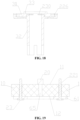
- the pressure sensor can be used in the sensor assembly 100 of the third embodiment, the pressure sensing unit 1 has a second through hole 64, the first section 221 of the conductive part is mechanically and electrically connected to the circuit unit 4 through two through holes, namely, the first through hole 63 of the sealing assembly and the second through hole 64 of the pressure sensing unit; the upper end face of the first flange part of the first section abuts against and seals with the lower end face of the sealing part, the detection channel 101 is communicated with the third through hole 65, the sensing film of the pressure sensing part 20 is exposed in the third through hole 65; of course, the pressure sensing unit 1 may also be used in the first and second embodiments.
- the base 3 takes the second section 222 of the conductive part as an injection molding insert and is molded by an inertmolding process, so as to seal and fix the second section 222 in the base 3.
Landscapes
- Physics & Mathematics (AREA)
- General Physics & Mathematics (AREA)
- Chemical & Material Sciences (AREA)
- Analytical Chemistry (AREA)
- Measuring Fluid Pressure (AREA)
Applications Claiming Priority (3)
| Application Number | Priority Date | Filing Date | Title |
|---|---|---|---|
| CN202011478788 | 2020-12-15 | ||
| CN202011589518.5A CN114636513B (zh) | 2020-12-15 | 2020-12-29 | 传感器组件以及阀装置 |
| PCT/CN2021/138250 WO2022127810A1 (fr) | 2020-12-15 | 2021-12-15 | Ensemble capteur et dispositif de soupape |
Publications (2)
| Publication Number | Publication Date |
|---|---|
| EP4266021A1 true EP4266021A1 (fr) | 2023-10-25 |
| EP4266021A4 EP4266021A4 (fr) | 2024-10-23 |
Family
ID=81945003
Family Applications (1)
| Application Number | Title | Priority Date | Filing Date |
|---|---|---|---|
| EP21905737.9A Pending EP4266021A4 (fr) | 2020-12-15 | 2021-12-15 | Ensemble capteur et dispositif de soupape |
Country Status (6)
| Country | Link |
|---|---|
| US (1) | US20240044734A1 (fr) |
| EP (1) | EP4266021A4 (fr) |
| JP (1) | JP7640702B2 (fr) |
| KR (1) | KR20230116933A (fr) |
| CN (3) | CN114636510A (fr) |
| WO (1) | WO2022127810A1 (fr) |
Families Citing this family (11)
| Publication number | Priority date | Publication date | Assignee | Title |
|---|---|---|---|---|
| CN115069190B (zh) * | 2022-07-26 | 2023-11-24 | 青岛丹香投资管理有限公司 | 一种食品反应釜用机械密封装置 |
| CN115096377B (zh) * | 2022-08-25 | 2022-11-25 | 无锡胜脉电子有限公司 | 一种温度压力传感器及其感温组件的组装工艺 |
| CN115435844A (zh) * | 2022-10-09 | 2022-12-06 | 无锡莱顿电子有限公司 | 一种温度压力传感器 |
| CN117213700A (zh) * | 2023-05-07 | 2023-12-12 | 武汉飞恩微电子有限公司 | 压力芯体单元、压力传感器、压力芯体组件及压差传感器 |
| CN117213698A (zh) * | 2023-05-07 | 2023-12-12 | 武汉飞恩微电子有限公司 | 压力芯体单元、压力感测组件及压力传感器 |
| CN117213699A (zh) * | 2023-05-07 | 2023-12-12 | 武汉飞恩微电子有限公司 | 压力芯体组件、压力感测组件及压差传感器 |
| CN116753645A (zh) * | 2023-06-19 | 2023-09-15 | 凯晟动力技术(嘉兴)有限公司 | 一种集成测试温度压力功能的电子膨胀阀 |
| CN116818156B (zh) * | 2023-08-30 | 2024-11-19 | 河北美泰电子科技有限公司 | Mems汽车压力传感器 |
| US20250102391A1 (en) * | 2023-09-27 | 2025-03-27 | Stmicroelectronics International N.V. | Pressure sensor with flange |
| DE102024107848A1 (de) * | 2024-03-19 | 2025-09-25 | Tdk Electronics Ag | Kernkomponente für eine Sensoranordnung und Sensoranordnung |
| CN118518064B (zh) * | 2024-06-17 | 2025-08-01 | 江西万年芯微电子有限公司 | 基于注塑成型的传感器紧固件、传感器及注塑加工方法 |
Family Cites Families (27)
| Publication number | Priority date | Publication date | Assignee | Title |
|---|---|---|---|---|
| JP3351922B2 (ja) * | 1994-12-22 | 2002-12-03 | 松下電工株式会社 | 半導体圧力センサの製造方法 |
| DE19723615A1 (de) * | 1997-06-05 | 1998-12-10 | Trw Automotive Electron & Comp | Drucksensoreinheit, insbesondere für die Kraftfahrzeugtechnik |
| US5974893A (en) * | 1997-07-24 | 1999-11-02 | Texas Instruments Incorporated | Combined pressure responsive transducer and temperature sensor apparatus |
| JP3319990B2 (ja) * | 1997-08-29 | 2002-09-03 | 三菱電機株式会社 | 圧力センサ装置 |
| JPH11295174A (ja) * | 1998-04-09 | 1999-10-29 | Fujikoki Corp | 圧力センサ |
| JP2000205983A (ja) * | 1999-01-07 | 2000-07-28 | Hokuriku Electric Ind Co Ltd | 静電容量型圧力センサユニット |
| JP2005300456A (ja) * | 2004-04-15 | 2005-10-27 | Denso Corp | 温度センサ一体型圧力センサ装置およびその取り付け方法 |
| DE102006034181B3 (de) * | 2006-07-24 | 2008-04-03 | Siemens Ag | Temperatursensor |
| US7478560B2 (en) * | 2007-03-08 | 2009-01-20 | Delphi Technologies, Inc. | Sensor apparatus responsive to pressure and temperature within a vessel |
| JP2008261796A (ja) * | 2007-04-13 | 2008-10-30 | Denso Corp | 温度センサ一体型圧力センサ装置 |
| ITTO20080484A1 (it) * | 2008-06-19 | 2009-12-20 | Eltek Spa | Dispositivo sensore di pressione |
| JP5279076B2 (ja) * | 2008-11-17 | 2013-09-04 | イーグル工業株式会社 | 金属ベローズ式アキュムレータ |
| JP2012047725A (ja) * | 2010-07-30 | 2012-03-08 | Canon Anelva Corp | 静電容量圧力センサ |
| JP5989307B2 (ja) * | 2011-06-21 | 2016-09-07 | トヨタ自動車株式会社 | シール構造 |
| JP5769298B2 (ja) * | 2011-07-06 | 2015-08-26 | 株式会社芝浦電子 | 温度センサ、温度及び圧力を検知する一体型センサ |
| CN202971904U (zh) * | 2012-12-13 | 2013-06-05 | 青岛北海油封有限公司 | 密封垫 |
| CN103047416B (zh) * | 2012-12-28 | 2015-11-25 | 北京华德广研密封件有限公司 | 适于压力容器的密封圈组件 |
| DE102014219030B4 (de) * | 2014-09-22 | 2016-07-07 | Robert Bosch Gmbh | Steckermodul |
| JP6301230B2 (ja) * | 2014-09-30 | 2018-03-28 | 長野計器株式会社 | 物理量測定装置 |
| ITUB20150460A1 (it) * | 2015-04-16 | 2016-10-16 | Metallux Sa | Sensore per la rilevazione di una o piu' grandezze di un fluido, particolarmente un sensore di pressione |
| KR102006750B1 (ko) * | 2018-11-16 | 2019-08-06 | 주식회사 신한전기 | 온도 및 압력 감지용 센서조립체 |
| CN209623933U (zh) * | 2019-03-20 | 2019-11-12 | 惠州比亚迪实业有限公司 | 流体压力感测装置 |
| CN110068416A (zh) * | 2019-05-28 | 2019-07-30 | 无锡莱顿电子有限公司 | 一种压力温度组合传感器 |
| CN210893467U (zh) * | 2019-11-07 | 2020-06-30 | 常州市雷利压力控制器有限公司 | 温度压力一体式传感器组件 |
| CN211602261U (zh) * | 2019-12-30 | 2020-09-29 | 苏州瞬通半导体科技有限公司 | 一种陶瓷压力传感器 |
| CN211877068U (zh) * | 2020-01-07 | 2020-11-06 | 深圳比亚迪微电子有限公司 | 传感器 |
| CN212133969U (zh) * | 2020-10-30 | 2020-12-11 | 南京新力感电子科技有限公司 | 一种传感器 |
-
2020
- 2020-12-29 CN CN202011587762.8A patent/CN114636510A/zh active Pending
- 2020-12-29 CN CN202011587536.XA patent/CN114636512B/zh active Active
- 2020-12-29 CN CN202011589518.5A patent/CN114636513B/zh active Active
-
2021
- 2021-12-15 JP JP2023535651A patent/JP7640702B2/ja active Active
- 2021-12-15 US US18/267,554 patent/US20240044734A1/en active Pending
- 2021-12-15 KR KR1020237023795A patent/KR20230116933A/ko active Pending
- 2021-12-15 EP EP21905737.9A patent/EP4266021A4/fr active Pending
- 2021-12-15 WO PCT/CN2021/138250 patent/WO2022127810A1/fr not_active Ceased
Also Published As
| Publication number | Publication date |
|---|---|
| CN114636512A (zh) | 2022-06-17 |
| JP2023552853A (ja) | 2023-12-19 |
| KR20230116933A (ko) | 2023-08-04 |
| CN114636513B (zh) | 2025-12-02 |
| CN114636510A (zh) | 2022-06-17 |
| CN114636513A (zh) | 2022-06-17 |
| WO2022127810A1 (fr) | 2022-06-23 |
| EP4266021A4 (fr) | 2024-10-23 |
| CN114636512B (zh) | 2025-11-28 |
| US20240044734A1 (en) | 2024-02-08 |
| JP7640702B2 (ja) | 2025-03-05 |
Similar Documents
| Publication | Publication Date | Title |
|---|---|---|
| EP4266021A1 (fr) | Ensemble capteur et dispositif de soupape | |
| EP3805710A1 (fr) | Capteur de température et de pression combiné | |
| US12598716B2 (en) | Sensor device and valve assembly with improved sealing features | |
| CN113108831A (zh) | 传感器 | |
| CN114427886A (zh) | 一种快速感温方形电容式温度压力传感器 | |
| CN216954627U (zh) | 一种快速感温方形电容式温度压力传感器 | |
| CN114526771B (zh) | 一体式温度压力传感器 | |
| CN212963461U (zh) | 传感器组件及阀装置 | |
| CN214748607U (zh) | 传感器 | |
| CN214066405U (zh) | 传感器装置 | |
| CN208350126U (zh) | 一种温度-压力一体式传感器 | |
| CN214308885U (zh) | 传感器 | |
| CN120063336A (zh) | 一种msg温压一体传感器及其组装方法 | |
| CN113266964A (zh) | 阀组件和传感器 | |
| CN219608101U (zh) | 一种温度压力传感器 | |
| WO2025241366A1 (fr) | Capteur de température et de pression à haute protection | |
| CN118508162A (zh) | 一种电连接件及压力传感器 | |
| CN214308835U (zh) | 传感器及阀装置 | |
| CN118225165A (zh) | 感应模组、传感器、热管理系统和车辆 | |
| CN113108829B (zh) | 传感器组件 | |
| CN214308834U (zh) | 传感器及阀装置 | |
| CN214748616U (zh) | 传感器和阀组件 | |
| CN214308833U (zh) | 传感器及阀装置 | |
| CN113108117A (zh) | 阀装置 | |
| CN115144124A (zh) | 传感器和阀组件 |
Legal Events
| Date | Code | Title | Description |
|---|---|---|---|
| STAA | Information on the status of an ep patent application or granted ep patent |
Free format text: STATUS: THE INTERNATIONAL PUBLICATION HAS BEEN MADE |
|
| PUAI | Public reference made under article 153(3) epc to a published international application that has entered the european phase |
Free format text: ORIGINAL CODE: 0009012 |
|
| STAA | Information on the status of an ep patent application or granted ep patent |
Free format text: STATUS: REQUEST FOR EXAMINATION WAS MADE |
|
| 17P | Request for examination filed |
Effective date: 20230714 |
|
| AK | Designated contracting states |
Kind code of ref document: A1 Designated state(s): AL AT BE BG CH CY CZ DE DK EE ES FI FR GB GR HR HU IE IS IT LI LT LU LV MC MK MT NL NO PL PT RO RS SE SI SK SM TR |
|
| DAV | Request for validation of the european patent (deleted) | ||
| DAX | Request for extension of the european patent (deleted) | ||
| A4 | Supplementary search report drawn up and despatched |
Effective date: 20240924 |
|
| RIC1 | Information provided on ipc code assigned before grant |
Ipc: G01D 21/02 20060101ALI20240918BHEP Ipc: G01K 13/02 20210101ALI20240918BHEP Ipc: G01L 19/14 20060101AFI20240918BHEP |