EP4266065B1 - Stromzähler zur erkennung einer betrügerischen öffnung - Google Patents
Stromzähler zur erkennung einer betrügerischen öffnung Download PDFInfo
- Publication number
- EP4266065B1 EP4266065B1 EP23162473.5A EP23162473A EP4266065B1 EP 4266065 B1 EP4266065 B1 EP 4266065B1 EP 23162473 A EP23162473 A EP 23162473A EP 4266065 B1 EP4266065 B1 EP 4266065B1
- Authority
- EP
- European Patent Office
- Prior art keywords
- supercapacitor
- electricity meter
- circuit
- electric power
- connection
- Prior art date
- Legal status (The legal status is an assumption and is not a legal conclusion. Google has not performed a legal analysis and makes no representation as to the accuracy of the status listed.)
- Active
Links
Images

Classifications
-
- G—PHYSICS
- G01—MEASURING; TESTING
- G01R—MEASURING ELECTRIC VARIABLES; MEASURING MAGNETIC VARIABLES
- G01R11/00—Electromechanical arrangements for measuring time integral of electric power or current, e.g. of consumption
- G01R11/02—Constructional details
- G01R11/24—Arrangements for avoiding or indicating fraudulent use
-
- G—PHYSICS
- G01—MEASURING; TESTING
- G01R—MEASURING ELECTRIC VARIABLES; MEASURING MAGNETIC VARIABLES
- G01R22/00—Arrangements for measuring time integral of electric power or current, e.g. electricity meters
- G01R22/06—Arrangements for measuring time integral of electric power or current, e.g. electricity meters by electronic methods
- G01R22/061—Details of electronic electricity meters
- G01R22/066—Arrangements for avoiding or indicating fraudulent use
-
- G—PHYSICS
- G08—SIGNALLING
- G08B—SIGNALLING SYSTEMS, e.g. PERSONAL CALLING SYSTEMS; ORDER TELEGRAPHS; ALARM SYSTEMS
- G08B13/00—Burglar, theft or intruder alarms
- G08B13/22—Electrical actuation
- G08B13/24—Electrical actuation by interference with electromagnetic field distribution
- G08B13/2491—Intrusion detection systems, i.e. where the body of an intruder causes the interference with the electromagnetic field
- G08B13/2497—Intrusion detection systems, i.e. where the body of an intruder causes the interference with the electromagnetic field using transmission lines, e.g. cable
-
- H—ELECTRICITY
- H02—GENERATION; CONVERSION OR DISTRIBUTION OF ELECTRIC POWER
- H02J—ELECTRIC POWER NETWORKS; CIRCUIT ARRANGEMENTS OR SYSTEMS FOR SUPPLYING OR DISTRIBUTING ELECTRIC POWER; SYSTEMS FOR STORING ELECTRIC ENERGY
- H02J7/00—Circuit arrangements for charging or discharging batteries or for supplying loads from batteries
- H02J7/34—Parallel operation in networks using both storage and other DC sources, e.g. providing buffering
- H02J7/345—Parallel operation in networks using both storage and other DC sources, e.g. providing buffering using capacitors as storage or buffering devices
-
- H—ELECTRICITY
- H02—GENERATION; CONVERSION OR DISTRIBUTION OF ELECTRIC POWER
- H02J—ELECTRIC POWER NETWORKS; CIRCUIT ARRANGEMENTS OR SYSTEMS FOR SUPPLYING OR DISTRIBUTING ELECTRIC POWER; SYSTEMS FOR STORING ELECTRIC ENERGY
- H02J7/00—Circuit arrangements for charging or discharging batteries or for supplying loads from batteries
- H02J7/865—Battery or charger load switching, e.g. concurrent charging and load supply
Definitions
- This solution requires maintaining microcontroller functions active throughout the power-off period, and therefore requires a battery capable of providing a significant energy reserve. The cost of the battery is therefore high. Furthermore, some customers refuse to use batteries in electricity meters.
- the electric meter comprises two housing elements which comprise a terminal cover and a cover, the discharge circuit comprising a first switch arranged to cooperate with the terminal cover and a second switch arranged to cooperate with the cover, the first switch and the second switch both being mounted in parallel with each other and with the supercapacitor.
- the holding circuit comprises two first transistors and a second transistor, the first two transistors being mounted head to tail, one of the first transistors having a terminal connected to said terminal of the supercapacitor and the other of the first transistors having a terminal connected to the input of the processing circuit, the second transistor being arranged to put the first transistors in an on state when the electric meter is under voltage and the supercapacitor is charged.
- the first transistors are P-channel MOSFET type transistors and the second transistor is an N-channel MOSFET type transistor, a gate of the second transistor being connected to the power supply circuit , a source of the second transistor being connected to an electrical ground, and a drain of the second transistor being connected to the gates of the first transistors.
- a computer-readable recording medium is provided, on which the computer program as previously described is recorded.
- the drain of the first transistor Q1 is connected to the second terminal 15 of the supercapacitor C1.
- meter 1 has an architecture with two microcontrollers: a metrology microcontroller belonging to a metrology part of meter 1, and an application microcontroller belonging to an application part of meter 1.
- the microcontroller 28 is powered by the power supply component 8 at 3.3V and is connected to the electrical ground 11.
- the microcontroller 28 includes an input 29 connected to the drain of the first transistor Q2.
- Input 29 is an I/O configured in mode I (Input).
- a resistor R5 is mounted so as to have a first terminal 30 connected to electrical ground 11 and a second terminal 31 connected to a point P2, which is itself connected to the drain of the first transistor Q2 and to input 29 of the microcontroller 28. This allows, when counter 1 is energized and supercapacitor C1 is discharged, to present a voltage of 0V at input 29 of microcontroller 28.
- Counter 1 also includes a communication module, which in this case is a CPL 32 modem (CPL for Carrier Current Online).
- CPL 32 modem uses the CPL G3 standard, but another type of standard could be used, for example CPL Prime.
- first power-up we designate any power-up occurring at any instant in the life of the meter 1.
- the power supply component 8 will recharge the supercapacitor C1 (the charging circuit has a time constant of 2 minutes). Therefore, the reading must be done fairly quickly, for example within a few seconds after restarting counter 1. In a few seconds, the charge of supercapacitor C1 does not have time to change significantly.
- the resistor R5 pulled towards ground 11 allows, when reading by the microcontroller 28 the voltage across the supercapacitor C1 and in the case where the supercapacitor C1 is discharged, in which case the first transistors Q1, Q2 are then in a blocked state, to apply a zero voltage to the input of the microcontroller 28 which therefore reads a state 0.
- the first transistors could be of the N-channel MOSFET type and the second transistor of the P-channel MOSFET type.
- the transistors are not necessarily MOSFETs. The number of transistors used could be different.
- the microcontroller which reads the voltage across the supercapacitor is not necessarily the application microcontroller, but could for example be, in an architecture with two microcontrollers, the metrology microcontroller.
- the CPL modem is preferably connected to the application microcontroller.
- Another component could be used to read the voltage across the supercapacitor. For example, it would be possible to connect a terminal of the supercapacitor to the input of an analog-to-digital converter (possibly integrated into the microcontroller). This would allow, rather than reading a “binary” detection signal, presenting a high state or a low state, to measure the voltage level across the supercapacitor. This measurement can for example be used to monitor the maximum charge of the supercapacitor and therefore its aging.
- the communication module is not necessarily a PLC modem.
- the alarm message can be transmitted by any existing means of communication, wired or not.
- Cellular communication for example using one of the LTE-M or NB-IoT standards, can thus be implemented.
Landscapes
- Physics & Mathematics (AREA)
- Engineering & Computer Science (AREA)
- Power Engineering (AREA)
- General Physics & Mathematics (AREA)
- Electromagnetism (AREA)
- Charge And Discharge Circuits For Batteries Or The Like (AREA)
- Measurement Of Current Or Voltage (AREA)
- Protection Of Static Devices (AREA)
- Arrangements For Transmission Of Measured Signals (AREA)
Claims (10)
- Stromzähler (1), umfassend:- ein Gehäuse (4), das mindestens ein Gehäuseelement (5, 6) umfasst, das im Betrieb üblicherweise geschlossen ist, aber geöffnet werden kann;- einen Superkondensator (C1);- eine Versorgungsschaltung (8), die ausgebildet ist, nach einem ersten Einschalten des Stromzählers den Superkondensator zu laden;- eine Halteschaltung (25), die ausgebildet ist, nach einem Abschalten des Stromzählers, das nach dem genannten ersten Einschalten erfolgt, zu verhindern, dass sich der Superkondensator entlädt, solange das Gehäuseelement geschlossen bleibt;- eine Entladungsschaltung (16), die ausgebildet ist, nach dem genannten Abschalten des Stromzählers den Superkondensator zu entladen, wenn das Gehäuseelement geöffnet ist; und- eine Verarbeitungsschaltung (27), die ausgebildet ist, nach einem zweiten Einschalten des Stromzählers, das nach dem genannten Abschalten erfolgt, ein Detektionssignal zu erfassen, das repräsentativ für eine Spannung an den Klemmen des Superkondensators ist und folglich für ein Ladungsniveau des Superkondensators, und zu detektieren, wenn der Superkondensator entladen ist, ob das Gehäuseelement nach dem genannten Abschalten des Stromzählers (1) geöffnet wurde, dadurch gekennzeichnet, dass:
die Halteschaltung zwei erste Transistoren (Q1, Q2) und einen zweiten Transistor (Q3) umfasst, wobei die beiden ersten Transistoren entgegengesetzt angeschlossen sind, wobei einer der ersten Transistoren (Q1) eine Klemme hat, die mit einer Klemme (15) des Superkondensators verbunden ist, und der andere der ersten Transistoren (Q2) eine Klemme hat, die mit einem Eingang (29) der Verarbeitungsschaltung verbunden ist, wobei der zweite Transistor ausgebildet ist, die ersten Transistoren in einen Durchlasszustand zu bringen, wenn der Stromzähler unter Spannung steht und wenn der Superkondensator (C1) geladen ist. - Stromzähler nach Anspruch 1, bei dem die Entladungsschaltung (16) mindestens einen Unterbrecher (I1, I2) umfasst, der parallel zum Superkondensator (C1) geschaltet ist, wobei der Unterbrecher ausgebildet ist, mit dem Gehäuseelement derart zusammenzuwirken, dass, wenn das Gehäuseelement geschlossen ist, der Unterbrecher geöffnet ist, und derart, dass, wenn das Gehäuseelement geöffnet ist, der Unterbrecher geschlossen ist und eine Entladung des Superkondensators (C1) verursacht.
- Stromzähler nach Anspruch 2, bei dem der Stromzähler zwei Gehäuseelemente umfasst, die einen Klemmendeckel (5) und eine Abdeckung (6) umfassen, wobei die Entladungsschaltung einen ersten Unterbrecher (I1) umfasst, der ausgebildet ist, mit dem Klemmendeckel (5) zusammenzuwirken, und einen zweiten Unterbrecher (12), der ausgebildet ist, mit der Abdeckung (6) zusammenzuwirken, wobei der erste Unterbrecher (I1) und der zweite Unterbrecher (12) alle beide parallel zueinander und zu dem Superkondensator (C1) geschaltet sind.
- Stromzähler nach einem der vorhergehenden Ansprüche, bei dem die Verarbeitungsschaltung (27) mit der Halteschaltung (25) verbunden ist, bei dem die Halteschaltung (25) mit der genannten Klemme (15) des Superkondensators (C1) verbunden ist und einen blockierten Zustand aufweist, wenn der Stromzähler (1) ohne Spannung ist, und einen Durchlasszustand, wenn der Stromzähler (1) unter Spannung ist, wobei die Verarbeitungsschaltung (27) und die Halteschaltung (25) so ausgebildet sind, dass, wenn der Stromzähler (1) unter Spannung ist, die Spannung an den Klemmen des Superkondensators an dem genannten Eingang (29) der Verarbeitungsschaltung (27) über die Halteschaltung (25) angelegt wird, wenn der Superkondensator (C1) geladen ist, und eine Spannung von 0V an dem genannten Eingang (29) angelegt wird, wenn der genannte Superkondensator (C1) entladen ist.
- Stromzähler nach Anspruch 1, bei dem die ersten Transistoren (Q1, Q2) Transistoren vom Typ P-Kanal MOSFET sind und der zweite Transistor (Q3) ein Transistor vom Typ N-Kanal MOSFET ist, wobei ein Gate des zweiten Transistors mit der Versorgungsschaltung verbunden ist, wobei eine Source des zweiten Transistors mit einer elektrischen Masse (11) verbunden ist, und ein Drain des zweiten Transistors mit den Gates der ersten Transistoren (Q1, Q2) verbunden ist.
- Detektionsverfahren, das in der Verbindungsschaltung (27) eines Stromzählers (1) nach einem der vorhergehenden Ansprüche durchgeführt wird und eine Detektionsphase umfasst, die nach dem zweiten Einschalten des Stromzählers (1), das nach dem genannten Abschalten erfolgt, die Schritte umfasst: Erfassen des Detektionssignals, das repräsentativ für die Spannung an den Klemmen des Superkondensators und folglich für ein Ladungsniveau des Superkondensators ist, und Detektieren, wenn der Superkondensator entladen ist, ob das Gehäuseelement nach dem genannten Abschalten des Stromzählers (1) geöffnet wurde.
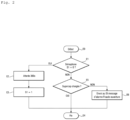
- Detektionsverfahren nach Anspruch 6, bei dem ein Semaphor von einem Computerprogramm definiert ist, das in der Verarbeitungsschaltung (27) implementiert wird, wobei das Semaphor zu Beginn der Herstellung des Stromzählers (1) einen ersten vordefinierten Wert hat, wobei das Detektionsverfahren ferner die Schritte umfasst, die bei jedem Einschalten des Stromzählers durchgeführt werden:- Lesen eines Werts des Semaphors, und:- wenn der Wert des Semaphors gleich dem ersten vordefinierten Wert ist, Abwarten für eine vordefinierte Dauer und dann Zuweisen eines vordefinierten zweiten Werts an das Semaphor auf endgültige Weise;- wenn der Wert des Semaphors gleich dem zweiten vordefinierten Wert ist, Durchführen der Detektionsphase.
- Detektionsverfahren nach einem der Ansprüche 6 bis 7, ferner umfassend, wenn die Verarbeitungsschaltung (27) erfasst hat, dass das Gehäuseelement nach dem Abschalten des Stromzählers geöffnet ist, die Schritte des Erzeugens und Aussendens einer Alarmnachricht.
- Computerprogramm, umfassend Anweisungen, die die Verarbeitungsschaltung (27) des Stromzählers (1) nach einem der Ansprüche 1 bis 5 dazu veranlassen, die Schritte des Detektionsverfahrens nach einem der Ansprüche 6 bis 8 auszuführen.
- Computerlesbarer Aufzeichnungsträger, auf dem das Computerprogramm nach Anspruch 9 gespeichert ist.
Applications Claiming Priority (1)
| Application Number | Priority Date | Filing Date | Title |
|---|---|---|---|
| FR2202631A FR3133927B1 (fr) | 2022-03-24 | 2022-03-24 | Compteur électrique agencé pour détecter une ouverture frauduleuse |
Publications (2)
| Publication Number | Publication Date |
|---|---|
| EP4266065A1 EP4266065A1 (de) | 2023-10-25 |
| EP4266065B1 true EP4266065B1 (de) | 2024-07-10 |
Family
ID=82019486
Family Applications (1)
| Application Number | Title | Priority Date | Filing Date |
|---|---|---|---|
| EP23162473.5A Active EP4266065B1 (de) | 2022-03-24 | 2023-03-16 | Stromzähler zur erkennung einer betrügerischen öffnung |
Country Status (5)
| Country | Link |
|---|---|
| US (1) | US12510572B2 (de) |
| EP (1) | EP4266065B1 (de) |
| CN (1) | CN116804681B (de) |
| ES (1) | ES2988656T3 (de) |
| FR (1) | FR3133927B1 (de) |
Family Cites Families (14)
| Publication number | Priority date | Publication date | Assignee | Title |
|---|---|---|---|---|
| US7644290B2 (en) * | 2003-03-31 | 2010-01-05 | Power Measurement Ltd. | System and method for seal tamper detection for intelligent electronic devices |
| US8818742B2 (en) * | 2011-03-25 | 2014-08-26 | General Electric Company | Systems, methods, and apparatus for detecting theft and status of electrical power |
| CN202119820U (zh) * | 2011-06-29 | 2012-01-18 | 深圳威胜科技有限公司 | 能在停电状态下检测开盖的电能表 |
| US8754634B2 (en) * | 2011-11-14 | 2014-06-17 | General Electric Company | System and method for tamper detection in a utility meter |
| CN104237587B (zh) * | 2013-06-23 | 2018-12-11 | 胡将龙 | 智能电网电力计量防窃电控制终端 |
| FR3027110B1 (fr) * | 2014-10-13 | 2016-11-04 | Sagemcom Energy & Telecom Sas | Equipement de mesure comportant des moyens de detection de fraude magnetique |
| FR3094498B1 (fr) * | 2019-03-25 | 2021-04-02 | Sagemcom Energy & Telecom Sas | Compteur électrique comprenant un circuit de détection d’un état ouvert ou fermé d’un disjoncteur |
| US11770073B2 (en) * | 2019-04-26 | 2023-09-26 | Texas Instruments Incorporated | Methods and apparatus for regulated hybrid converters |
| CN110554228A (zh) * | 2019-09-04 | 2019-12-10 | 中国电力科学研究院有限公司 | 一种用于电表停止运行状态记录开盖检测的方法及系统 |
| CN110635803B (zh) * | 2019-10-07 | 2024-06-14 | 珠海一微半导体股份有限公司 | 一种基于电平宽度提取的锁相加速电路及锁相环系统 |
| CN110794188A (zh) * | 2019-11-14 | 2020-02-14 | 浙江晨泰科技股份有限公司 | 防窃电表 |
| US11309727B2 (en) * | 2020-03-26 | 2022-04-19 | Landis+Gyr Innovations, Inc. | Utility meter with solar-powered real-time clock |
| US11258299B1 (en) * | 2020-11-03 | 2022-02-22 | Landis+Gyr Innovations, Inc. | Generating charge for service disconnect operation |
| US11847507B1 (en) * | 2020-12-02 | 2023-12-19 | Amazon Technologies, Inc. | DMA synchronization using alternating semaphores |
-
2022
- 2022-03-24 FR FR2202631A patent/FR3133927B1/fr not_active Expired - Fee Related
-
2023
- 2023-03-16 ES ES23162473T patent/ES2988656T3/es active Active
- 2023-03-16 EP EP23162473.5A patent/EP4266065B1/de active Active
- 2023-03-24 US US18/189,534 patent/US12510572B2/en active Active
- 2023-03-24 CN CN202310301657.0A patent/CN116804681B/zh active Active
Also Published As
| Publication number | Publication date |
|---|---|
| ES2988656T3 (es) | 2024-11-21 |
| FR3133927B1 (fr) | 2024-05-03 |
| EP4266065A1 (de) | 2023-10-25 |
| US12510572B2 (en) | 2025-12-30 |
| FR3133927A1 (fr) | 2023-09-29 |
| US20230305044A1 (en) | 2023-09-28 |
| CN116804681B (zh) | 2025-08-29 |
| CN116804681A (zh) | 2023-09-26 |
Similar Documents
| Publication | Publication Date | Title |
|---|---|---|
| EP4189766B1 (de) | Modulares, in serie geschaltetes batteriepack (blmose) | |
| EP2721684B1 (de) | Batteriezellensystem mit vereinfachter überwachung | |
| FR2951886A1 (fr) | Commande avec ralentissement de l'ouverture d'un interrupteur electronique | |
| CA2692300C (fr) | Procede et systeme de gestion de coupures d'alimentation electrique a bord d'un aeronef | |
| FR2702885A1 (fr) | Système de contrôle de vieillissement d'une batterie et procédé mis en Óoeuvre dans un tel système. | |
| FR2475307A1 (fr) | Circuit d'alimentation de secours par batterie de faible puissance pour une memoire a semi-conducteur | |
| FR2944647A1 (fr) | Procede de diagnostic de la defaillance d'un generateur photovoltaique | |
| EP1936541B1 (de) | Ein/aus Batterieladegerät mit Versorgungsschutzschaltung für eine monolithische integrierte Schaltung die verwendet die Energie von der Antenne | |
| FR3094498A1 (fr) | Compteur électrique comprenant un circuit de détection d’un état ouvert ou fermé d’un disjoncteur | |
| EP4266065B1 (de) | Stromzähler zur erkennung einer betrügerischen öffnung | |
| FR2908939A1 (fr) | Dispositif de commande pour assurer la regulation en tension d'un bus d'alimentation. | |
| FR2965627A1 (fr) | Systeme de gestion d'un dispositif photovoltaique | |
| EP3358307A1 (de) | Verfahren zur verwaltung einer hilfsstromversorgung eines zählers | |
| FR2965626A1 (fr) | Systeme de gestion d'un dispositif photovoltaique | |
| FR2965628A1 (fr) | Systeme de gestion d'un dispositif photovoltaique | |
| EP3631476A1 (de) | Einphasiger stromzähler | |
| FR2870996A1 (fr) | Protection de circuit electrique en mode veille pour vehicule | |
| EP4184183B1 (de) | Erkennung des offenen oder geschlossenen zustandes eines leistungsschalters | |
| EP1432096A2 (de) | Konstantspannung-Ladungszustandsteuervorrichtung für eine Einheit mit sekundären elektrochemischen Generatoren | |
| FR3091127A1 (fr) | Equipement électrique qui accède, dans un mode de fonctionnement alternatif, à un réseau de téléphonie mobile. | |
| FR2474776A1 (fr) | Appareil pour la charge d'une batterie rechargeable | |
| FR2497033A1 (fr) | Attenuateur pour signal electrique | |
| FR2719947A1 (fr) | Procédé et dispositif d'entretien d'un accumulateur utilisé en marche flottante, notamment pour un appareil de sécurité. | |
| FR3089073A1 (fr) | Système de commande de modules accumulateurs électriques | |
| WO2012041969A1 (fr) | Système de gestion d'un dispositif photovoltaïque |
Legal Events
| Date | Code | Title | Description |
|---|---|---|---|
| PUAI | Public reference made under article 153(3) epc to a published international application that has entered the european phase |
Free format text: ORIGINAL CODE: 0009012 |
|
| STAA | Information on the status of an ep patent application or granted ep patent |
Free format text: STATUS: REQUEST FOR EXAMINATION WAS MADE |
|
| 17P | Request for examination filed |
Effective date: 20230316 |
|
| AK | Designated contracting states |
Kind code of ref document: A1 Designated state(s): AL AT BE BG CH CY CZ DE DK EE ES FI FR GB GR HR HU IE IS IT LI LT LU LV MC ME MK MT NL NO PL PT RO RS SE SI SK SM TR |
|
| RAP3 | Party data changed (applicant data changed or rights of an application transferred) |
Owner name: SAGEMCOM ENERGY & TELECOM SAS |
|
| GRAP | Despatch of communication of intention to grant a patent |
Free format text: ORIGINAL CODE: EPIDOSNIGR1 |
|
| STAA | Information on the status of an ep patent application or granted ep patent |
Free format text: STATUS: GRANT OF PATENT IS INTENDED |
|
| INTG | Intention to grant announced |
Effective date: 20240202 |
|
| RBV | Designated contracting states (corrected) |
Designated state(s): AL AT BE BG CH CY CZ DE DK EE ES FI FR GB GR HR HU IE IS IT LI LT LU LV MC ME MK MT NL NO PL PT RO RS SE SI SK SM TR |
|
| GRAS | Grant fee paid |
Free format text: ORIGINAL CODE: EPIDOSNIGR3 |
|
| GRAA | (expected) grant |
Free format text: ORIGINAL CODE: 0009210 |
|
| STAA | Information on the status of an ep patent application or granted ep patent |
Free format text: STATUS: THE PATENT HAS BEEN GRANTED |
|
| AK | Designated contracting states |
Kind code of ref document: B1 Designated state(s): AL AT BE BG CH CY CZ DE DK EE ES FI FR GB GR HR HU IE IS IT LI LT LU LV MC ME MK MT NL NO PL PT RO RS SE SI SK SM TR |
|
| REG | Reference to a national code |
Ref country code: CH Ref legal event code: EP |
|
| REG | Reference to a national code |
Ref country code: DE Ref legal event code: R096 Ref document number: 602023000216 Country of ref document: DE |
|
| P01 | Opt-out of the competence of the unified patent court (upc) registered |
Free format text: CASE NUMBER: APP_40551/2024 Effective date: 20240709 |
|
| REG | Reference to a national code |
Ref country code: NL Ref legal event code: FP |
|
| REG | Reference to a national code |
Ref country code: LT Ref legal event code: MG9D |
|
| REG | Reference to a national code |
Ref country code: ES Ref legal event code: FG2A Ref document number: 2988656 Country of ref document: ES Kind code of ref document: T3 Effective date: 20241121 |
|
| PG25 | Lapsed in a contracting state [announced via postgrant information from national office to epo] |
Ref country code: PT Free format text: LAPSE BECAUSE OF FAILURE TO SUBMIT A TRANSLATION OF THE DESCRIPTION OR TO PAY THE FEE WITHIN THE PRESCRIBED TIME-LIMIT Effective date: 20241111 |
|
| REG | Reference to a national code |
Ref country code: AT Ref legal event code: MK05 Ref document number: 1702484 Country of ref document: AT Kind code of ref document: T Effective date: 20240710 |
|
| PG25 | Lapsed in a contracting state [announced via postgrant information from national office to epo] |
Ref country code: PT Free format text: LAPSE BECAUSE OF FAILURE TO SUBMIT A TRANSLATION OF THE DESCRIPTION OR TO PAY THE FEE WITHIN THE PRESCRIBED TIME-LIMIT Effective date: 20241111 |
|
| PG25 | Lapsed in a contracting state [announced via postgrant information from national office to epo] |
Ref country code: NO Free format text: LAPSE BECAUSE OF FAILURE TO SUBMIT A TRANSLATION OF THE DESCRIPTION OR TO PAY THE FEE WITHIN THE PRESCRIBED TIME-LIMIT Effective date: 20241010 |
|
| PG25 | Lapsed in a contracting state [announced via postgrant information from national office to epo] |
Ref country code: GR Free format text: LAPSE BECAUSE OF FAILURE TO SUBMIT A TRANSLATION OF THE DESCRIPTION OR TO PAY THE FEE WITHIN THE PRESCRIBED TIME-LIMIT Effective date: 20241011 Ref country code: FI Free format text: LAPSE BECAUSE OF FAILURE TO SUBMIT A TRANSLATION OF THE DESCRIPTION OR TO PAY THE FEE WITHIN THE PRESCRIBED TIME-LIMIT Effective date: 20240710 Ref country code: PL Free format text: LAPSE BECAUSE OF FAILURE TO SUBMIT A TRANSLATION OF THE DESCRIPTION OR TO PAY THE FEE WITHIN THE PRESCRIBED TIME-LIMIT Effective date: 20240710 |
|
| PG25 | Lapsed in a contracting state [announced via postgrant information from national office to epo] |
Ref country code: BG Free format text: LAPSE BECAUSE OF FAILURE TO SUBMIT A TRANSLATION OF THE DESCRIPTION OR TO PAY THE FEE WITHIN THE PRESCRIBED TIME-LIMIT Effective date: 20240710 |
|
| PG25 | Lapsed in a contracting state [announced via postgrant information from national office to epo] |
Ref country code: LV Free format text: LAPSE BECAUSE OF FAILURE TO SUBMIT A TRANSLATION OF THE DESCRIPTION OR TO PAY THE FEE WITHIN THE PRESCRIBED TIME-LIMIT Effective date: 20240710 |
|
| PG25 | Lapsed in a contracting state [announced via postgrant information from national office to epo] |
Ref country code: AT Free format text: LAPSE BECAUSE OF FAILURE TO SUBMIT A TRANSLATION OF THE DESCRIPTION OR TO PAY THE FEE WITHIN THE PRESCRIBED TIME-LIMIT Effective date: 20240710 Ref country code: IS Free format text: LAPSE BECAUSE OF FAILURE TO SUBMIT A TRANSLATION OF THE DESCRIPTION OR TO PAY THE FEE WITHIN THE PRESCRIBED TIME-LIMIT Effective date: 20241110 |
|
| PG25 | Lapsed in a contracting state [announced via postgrant information from national office to epo] |
Ref country code: HR Free format text: LAPSE BECAUSE OF FAILURE TO SUBMIT A TRANSLATION OF THE DESCRIPTION OR TO PAY THE FEE WITHIN THE PRESCRIBED TIME-LIMIT Effective date: 20240710 |
|
| PG25 | Lapsed in a contracting state [announced via postgrant information from national office to epo] |
Ref country code: RS Free format text: LAPSE BECAUSE OF FAILURE TO SUBMIT A TRANSLATION OF THE DESCRIPTION OR TO PAY THE FEE WITHIN THE PRESCRIBED TIME-LIMIT Effective date: 20241010 |
|
| PG25 | Lapsed in a contracting state [announced via postgrant information from national office to epo] |
Ref country code: RS Free format text: LAPSE BECAUSE OF FAILURE TO SUBMIT A TRANSLATION OF THE DESCRIPTION OR TO PAY THE FEE WITHIN THE PRESCRIBED TIME-LIMIT Effective date: 20241010 Ref country code: PL Free format text: LAPSE BECAUSE OF FAILURE TO SUBMIT A TRANSLATION OF THE DESCRIPTION OR TO PAY THE FEE WITHIN THE PRESCRIBED TIME-LIMIT Effective date: 20240710 Ref country code: NO Free format text: LAPSE BECAUSE OF FAILURE TO SUBMIT A TRANSLATION OF THE DESCRIPTION OR TO PAY THE FEE WITHIN THE PRESCRIBED TIME-LIMIT Effective date: 20241010 Ref country code: LV Free format text: LAPSE BECAUSE OF FAILURE TO SUBMIT A TRANSLATION OF THE DESCRIPTION OR TO PAY THE FEE WITHIN THE PRESCRIBED TIME-LIMIT Effective date: 20240710 Ref country code: IS Free format text: LAPSE BECAUSE OF FAILURE TO SUBMIT A TRANSLATION OF THE DESCRIPTION OR TO PAY THE FEE WITHIN THE PRESCRIBED TIME-LIMIT Effective date: 20241110 Ref country code: HR Free format text: LAPSE BECAUSE OF FAILURE TO SUBMIT A TRANSLATION OF THE DESCRIPTION OR TO PAY THE FEE WITHIN THE PRESCRIBED TIME-LIMIT Effective date: 20240710 Ref country code: GR Free format text: LAPSE BECAUSE OF FAILURE TO SUBMIT A TRANSLATION OF THE DESCRIPTION OR TO PAY THE FEE WITHIN THE PRESCRIBED TIME-LIMIT Effective date: 20241011 Ref country code: FI Free format text: LAPSE BECAUSE OF FAILURE TO SUBMIT A TRANSLATION OF THE DESCRIPTION OR TO PAY THE FEE WITHIN THE PRESCRIBED TIME-LIMIT Effective date: 20240710 Ref country code: BG Free format text: LAPSE BECAUSE OF FAILURE TO SUBMIT A TRANSLATION OF THE DESCRIPTION OR TO PAY THE FEE WITHIN THE PRESCRIBED TIME-LIMIT Effective date: 20240710 Ref country code: AT Free format text: LAPSE BECAUSE OF FAILURE TO SUBMIT A TRANSLATION OF THE DESCRIPTION OR TO PAY THE FEE WITHIN THE PRESCRIBED TIME-LIMIT Effective date: 20240710 |
|
| REG | Reference to a national code |
Ref country code: DE Ref legal event code: R097 Ref document number: 602023000216 Country of ref document: DE |
|
| PG25 | Lapsed in a contracting state [announced via postgrant information from national office to epo] |
Ref country code: DK Free format text: LAPSE BECAUSE OF FAILURE TO SUBMIT A TRANSLATION OF THE DESCRIPTION OR TO PAY THE FEE WITHIN THE PRESCRIBED TIME-LIMIT Effective date: 20240710 Ref country code: RO Free format text: LAPSE BECAUSE OF FAILURE TO SUBMIT A TRANSLATION OF THE DESCRIPTION OR TO PAY THE FEE WITHIN THE PRESCRIBED TIME-LIMIT Effective date: 20240710 Ref country code: SM Free format text: LAPSE BECAUSE OF FAILURE TO SUBMIT A TRANSLATION OF THE DESCRIPTION OR TO PAY THE FEE WITHIN THE PRESCRIBED TIME-LIMIT Effective date: 20240710 |
|
| PG25 | Lapsed in a contracting state [announced via postgrant information from national office to epo] |
Ref country code: EE Free format text: LAPSE BECAUSE OF FAILURE TO SUBMIT A TRANSLATION OF THE DESCRIPTION OR TO PAY THE FEE WITHIN THE PRESCRIBED TIME-LIMIT Effective date: 20240710 |
|
| PGFP | Annual fee paid to national office [announced via postgrant information from national office to epo] |
Ref country code: CZ Payment date: 20250225 Year of fee payment: 3 |
|
| PG25 | Lapsed in a contracting state [announced via postgrant information from national office to epo] |
Ref country code: IT Free format text: LAPSE BECAUSE OF FAILURE TO SUBMIT A TRANSLATION OF THE DESCRIPTION OR TO PAY THE FEE WITHIN THE PRESCRIBED TIME-LIMIT Effective date: 20240710 Ref country code: SK Free format text: LAPSE BECAUSE OF FAILURE TO SUBMIT A TRANSLATION OF THE DESCRIPTION OR TO PAY THE FEE WITHIN THE PRESCRIBED TIME-LIMIT Effective date: 20240710 |
|
| PLBE | No opposition filed within time limit |
Free format text: ORIGINAL CODE: 0009261 |
|
| STAA | Information on the status of an ep patent application or granted ep patent |
Free format text: STATUS: NO OPPOSITION FILED WITHIN TIME LIMIT |
|
| 26N | No opposition filed |
Effective date: 20250411 |
|
| PGFP | Annual fee paid to national office [announced via postgrant information from national office to epo] |
Ref country code: ES Payment date: 20250401 Year of fee payment: 3 |
|
| PG25 | Lapsed in a contracting state [announced via postgrant information from national office to epo] |
Ref country code: SE Free format text: LAPSE BECAUSE OF FAILURE TO SUBMIT A TRANSLATION OF THE DESCRIPTION OR TO PAY THE FEE WITHIN THE PRESCRIBED TIME-LIMIT Effective date: 20240710 |
|
| PG25 | Lapsed in a contracting state [announced via postgrant information from national office to epo] |
Ref country code: MC Free format text: LAPSE BECAUSE OF FAILURE TO SUBMIT A TRANSLATION OF THE DESCRIPTION OR TO PAY THE FEE WITHIN THE PRESCRIBED TIME-LIMIT Effective date: 20240710 |
|
| PG25 | Lapsed in a contracting state [announced via postgrant information from national office to epo] |
Ref country code: LU Free format text: LAPSE BECAUSE OF NON-PAYMENT OF DUE FEES Effective date: 20250316 |
|
| PGFP | Annual fee paid to national office [announced via postgrant information from national office to epo] |
Ref country code: NL Payment date: 20260219 Year of fee payment: 4 |
|
| REG | Reference to a national code |
Ref country code: CH Ref legal event code: U11 Free format text: ST27 STATUS EVENT CODE: U-0-0-U10-U11 (AS PROVIDED BY THE NATIONAL OFFICE) Effective date: 20260401 |
|
| PGFP | Annual fee paid to national office [announced via postgrant information from national office to epo] |
Ref country code: IE Payment date: 20260223 Year of fee payment: 4 Ref country code: DE Payment date: 20260219 Year of fee payment: 4 |
|
| PGFP | Annual fee paid to national office [announced via postgrant information from national office to epo] |
Ref country code: BE Payment date: 20260219 Year of fee payment: 4 |
|
| PGFP | Annual fee paid to national office [announced via postgrant information from national office to epo] |
Ref country code: FR Payment date: 20260219 Year of fee payment: 4 |