EP4266448A1 - Procédé de commande de charge et système de commande de charge - Google Patents
Procédé de commande de charge et système de commande de charge Download PDFInfo
- Publication number
- EP4266448A1 EP4266448A1 EP20966179.2A EP20966179A EP4266448A1 EP 4266448 A1 EP4266448 A1 EP 4266448A1 EP 20966179 A EP20966179 A EP 20966179A EP 4266448 A1 EP4266448 A1 EP 4266448A1
- Authority
- EP
- European Patent Office
- Prior art keywords
- voltage battery
- temperature
- battery
- charging
- secondary battery
- Prior art date
- Legal status (The legal status is an assumption and is not a legal conclusion. Google has not performed a legal analysis and makes no representation as to the accuracy of the status listed.)
- Pending
Links
Images







Classifications
-
- H—ELECTRICITY
- H02—GENERATION; CONVERSION OR DISTRIBUTION OF ELECTRIC POWER
- H02J—ELECTRIC POWER NETWORKS; CIRCUIT ARRANGEMENTS OR SYSTEMS FOR SUPPLYING OR DISTRIBUTING ELECTRIC POWER; SYSTEMS FOR STORING ELECTRIC ENERGY
- H02J7/00—Circuit arrangements for charging or discharging batteries or for supplying loads from batteries
- H02J7/90—Regulation of charging or discharging current or voltage
- H02J7/971—Regulation of charging or discharging current or voltage the charge cycle being controlled or terminated in response to non-electric parameters
- H02J7/975—Regulation of charging or discharging current or voltage the charge cycle being controlled or terminated in response to non-electric parameters in response to temperature
- H02J7/977—Regulation of charging or discharging current or voltage the charge cycle being controlled or terminated in response to non-electric parameters in response to temperature of the battery
-
- H—ELECTRICITY
- H01—ELECTRIC ELEMENTS
- H01M—PROCESSES OR MEANS, e.g. BATTERIES, FOR THE DIRECT CONVERSION OF CHEMICAL ENERGY INTO ELECTRICAL ENERGY
- H01M10/00—Secondary cells; Manufacture thereof
- H01M10/42—Methods or arrangements for servicing or maintenance of secondary cells or secondary half-cells
- H01M10/44—Methods for charging or discharging
-
- H—ELECTRICITY
- H01—ELECTRIC ELEMENTS
- H01M—PROCESSES OR MEANS, e.g. BATTERIES, FOR THE DIRECT CONVERSION OF CHEMICAL ENERGY INTO ELECTRICAL ENERGY
- H01M10/00—Secondary cells; Manufacture thereof
- H01M10/42—Methods or arrangements for servicing or maintenance of secondary cells or secondary half-cells
- H01M10/44—Methods for charging or discharging
- H01M10/443—Methods for charging or discharging in response to temperature
-
- H—ELECTRICITY
- H01—ELECTRIC ELEMENTS
- H01M—PROCESSES OR MEANS, e.g. BATTERIES, FOR THE DIRECT CONVERSION OF CHEMICAL ENERGY INTO ELECTRICAL ENERGY
- H01M10/00—Secondary cells; Manufacture thereof
- H01M10/42—Methods or arrangements for servicing or maintenance of secondary cells or secondary half-cells
- H01M10/48—Accumulators combined with arrangements for measuring, testing or indicating the condition of cells, e.g. the level or density of the electrolyte
-
- H—ELECTRICITY
- H01—ELECTRIC ELEMENTS
- H01M—PROCESSES OR MEANS, e.g. BATTERIES, FOR THE DIRECT CONVERSION OF CHEMICAL ENERGY INTO ELECTRICAL ENERGY
- H01M10/00—Secondary cells; Manufacture thereof
- H01M10/42—Methods or arrangements for servicing or maintenance of secondary cells or secondary half-cells
- H01M10/48—Accumulators combined with arrangements for measuring, testing or indicating the condition of cells, e.g. the level or density of the electrolyte
- H01M10/486—Accumulators combined with arrangements for measuring, testing or indicating the condition of cells, e.g. the level or density of the electrolyte for measuring temperature
-
- H—ELECTRICITY
- H01—ELECTRIC ELEMENTS
- H01M—PROCESSES OR MEANS, e.g. BATTERIES, FOR THE DIRECT CONVERSION OF CHEMICAL ENERGY INTO ELECTRICAL ENERGY
- H01M10/00—Secondary cells; Manufacture thereof
- H01M10/60—Heating or cooling; Temperature control
- H01M10/61—Types of temperature control
- H01M10/613—Cooling or keeping cold
-
- H—ELECTRICITY
- H01—ELECTRIC ELEMENTS
- H01M—PROCESSES OR MEANS, e.g. BATTERIES, FOR THE DIRECT CONVERSION OF CHEMICAL ENERGY INTO ELECTRICAL ENERGY
- H01M10/00—Secondary cells; Manufacture thereof
- H01M10/60—Heating or cooling; Temperature control
- H01M10/61—Types of temperature control
- H01M10/615—Heating or keeping warm
-
- H—ELECTRICITY
- H01—ELECTRIC ELEMENTS
- H01M—PROCESSES OR MEANS, e.g. BATTERIES, FOR THE DIRECT CONVERSION OF CHEMICAL ENERGY INTO ELECTRICAL ENERGY
- H01M10/00—Secondary cells; Manufacture thereof
- H01M10/60—Heating or cooling; Temperature control
- H01M10/62—Heating or cooling; Temperature control specially adapted for specific applications
- H01M10/625—Vehicles
-
- H—ELECTRICITY
- H01—ELECTRIC ELEMENTS
- H01M—PROCESSES OR MEANS, e.g. BATTERIES, FOR THE DIRECT CONVERSION OF CHEMICAL ENERGY INTO ELECTRICAL ENERGY
- H01M10/00—Secondary cells; Manufacture thereof
- H01M10/60—Heating or cooling; Temperature control
- H01M10/63—Control systems
-
- H—ELECTRICITY
- H01—ELECTRIC ELEMENTS
- H01M—PROCESSES OR MEANS, e.g. BATTERIES, FOR THE DIRECT CONVERSION OF CHEMICAL ENERGY INTO ELECTRICAL ENERGY
- H01M10/00—Secondary cells; Manufacture thereof
- H01M10/60—Heating or cooling; Temperature control
- H01M10/63—Control systems
- H01M10/633—Control systems characterised by algorithms, flow charts, software details or the like
-
- H—ELECTRICITY
- H02—GENERATION; CONVERSION OR DISTRIBUTION OF ELECTRIC POWER
- H02J—ELECTRIC POWER NETWORKS; CIRCUIT ARRANGEMENTS OR SYSTEMS FOR SUPPLYING OR DISTRIBUTING ELECTRIC POWER; SYSTEMS FOR STORING ELECTRIC ENERGY
- H02J7/00—Circuit arrangements for charging or discharging batteries or for supplying loads from batteries
- H02J7/40—Circuit arrangements for charging or discharging batteries or for supplying loads from batteries characterised by the exchange of charge or discharge related data
-
- H—ELECTRICITY
- H02—GENERATION; CONVERSION OR DISTRIBUTION OF ELECTRIC POWER
- H02J—ELECTRIC POWER NETWORKS; CIRCUIT ARRANGEMENTS OR SYSTEMS FOR SUPPLYING OR DISTRIBUTING ELECTRIC POWER; SYSTEMS FOR STORING ELECTRIC ENERGY
- H02J7/00—Circuit arrangements for charging or discharging batteries or for supplying loads from batteries
- H02J7/60—Circuit arrangements for charging or discharging batteries or for supplying loads from batteries including safety or protection arrangements
-
- H—ELECTRICITY
- H02—GENERATION; CONVERSION OR DISTRIBUTION OF ELECTRIC POWER
- H02J—ELECTRIC POWER NETWORKS; CIRCUIT ARRANGEMENTS OR SYSTEMS FOR SUPPLYING OR DISTRIBUTING ELECTRIC POWER; SYSTEMS FOR STORING ELECTRIC ENERGY
- H02J7/00—Circuit arrangements for charging or discharging batteries or for supplying loads from batteries
- H02J7/90—Regulation of charging or discharging current or voltage
- H02J7/971—Regulation of charging or discharging current or voltage the charge cycle being controlled or terminated in response to non-electric parameters
-
- B—PERFORMING OPERATIONS; TRANSPORTING
- B60—VEHICLES IN GENERAL
- B60L—PROPULSION OF ELECTRICALLY-PROPELLED VEHICLES; SUPPLYING ELECTRIC POWER FOR AUXILIARY EQUIPMENT OF ELECTRICALLY-PROPELLED VEHICLES; ELECTRODYNAMIC BRAKE SYSTEMS FOR VEHICLES IN GENERAL; MAGNETIC SUSPENSION OR LEVITATION FOR VEHICLES; MONITORING OPERATING VARIABLES OF ELECTRICALLY-PROPELLED VEHICLES; ELECTRIC SAFETY DEVICES FOR ELECTRICALLY-PROPELLED VEHICLES
- B60L53/00—Methods of charging batteries, specially adapted for electric vehicles; Charging stations or on-board charging equipment therefor; Exchange of energy storage elements in electric vehicles
- B60L53/60—Monitoring or controlling charging stations
- B60L53/62—Monitoring or controlling charging stations in response to charging parameters, e.g. current, voltage or electrical charge
-
- Y—GENERAL TAGGING OF NEW TECHNOLOGICAL DEVELOPMENTS; GENERAL TAGGING OF CROSS-SECTIONAL TECHNOLOGIES SPANNING OVER SEVERAL SECTIONS OF THE IPC; TECHNICAL SUBJECTS COVERED BY FORMER USPC CROSS-REFERENCE ART COLLECTIONS [XRACs] AND DIGESTS
- Y02—TECHNOLOGIES OR APPLICATIONS FOR MITIGATION OR ADAPTATION AGAINST CLIMATE CHANGE
- Y02E—REDUCTION OF GREENHOUSE GAS [GHG] EMISSIONS, RELATED TO ENERGY GENERATION, TRANSMISSION OR DISTRIBUTION
- Y02E60/00—Enabling technologies; Technologies with a potential or indirect contribution to GHG emissions mitigation
- Y02E60/10—Energy storage using batteries
Definitions
- the present invention relates to a charging control method and a charging control system that control charging of a secondary battery.
- JP2006-197727A discloses a technique of determining a current value for charging a secondary battery based on a remaining capacity of the secondary battery.
- the secondary battery is charged by the current value determined based on the remaining capacity of the secondary battery.
- an amount of heat generation by the secondary battery is determined based on a current and an internal resistance. Therefore, in order to continuously execute the charging, it is important to set an appropriate charging current value in consideration of the amount of heat generation, and to limit an increase in a temperature of the secondary battery during charging.
- An object of the present invention is to continue charging a secondary battery while limiting an increase in a temperature of the secondary battery.
- the method includes: an acquisition step of acquiring information on heat of the secondary battery; and a control step of setting, based on the information on the heat of the secondary battery, a charging current value of the secondary battery to control an amount of heat generation by the secondary battery to a predetermined value.
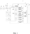
- FIG. 1 is a block diagram illustrating a configuration example of a control system for secondary battery 1 according to an embodiment.
- the control system for secondary battery 1 is a system that controls charging and discharging of a secondary battery mounted on a vehicle such as an electric vehicle or a hybrid vehicle.
- the secondary battery supplies electric power to a vehicle-mounted device of the vehicle, such as a drive motor or an auxiliary machine.
- the secondary battery is also a battery that can be charged by a charger serving as a vehicle-mounted device or a charging device outside the vehicle.
- a lithium ion battery, a lead-acid battery, or a nickel metal hydride battery can be used as the secondary battery.
- a secondary battery mounted on a movable body will be described as an example, but the present invention can also be applied to a secondary battery mounted on a stationary body.
- the control system for secondary battery 1 includes a vehicle control module (VCM) 10, a direct current (DC)/DC 20, an air conditioner (AC) 30, a positive temperature coefficient (PTC) 40, an inverter (INV) 50, a motor (MOT) 60, a charger 70, a secondary battery unit 100, and a battery management unit (BMS) 160.
- VCM vehicle control module
- DC direct current
- AC air conditioner
- PTC positive temperature coefficient
- IMV inverter
- MOT motor
- charger 70 a charger 70
- BMS battery management unit
- the secondary battery unit 100 is implemented by housing a high-voltage battery 110, a service disconnect switch (SDSW) 111, and a relay 112 in a battery case.
- the high-voltage battery 110 includes a plurality of traveling batteries. A reason why the high-voltage battery 110 is referred to as the traveling batteries is that electric power of the high-voltage battery 110 is mainly supplied to the MOT 60. Obviously, the electric power is also supplied to other electric loads. In the present embodiment, the high-voltage battery 110 is simply referred to as the term "battery".
- the SDSW 111 is a switch for switching ON/OFF of a high-current circuit of the high-voltage battery 110. That is, it is possible to cut off a circuit by operating the SDSW 111 during operating or in an emergency, and to safely take measures during the operating or in the emergency.
- the relay 112 is a relay that switches ON/OFF of charging and discharging of the high-voltage battery 110 based on a control signal from the VCM 10 via a signal line 11.
- Temperature sensors 121 to 123, a current sensor 130, a total voltage sensor 140, and cell voltage sensors 151 to 153 are provided inside or outside the secondary battery unit 100.
- the temperature sensors 121 to 123 are temperature sensors that detect a temperature of the high-voltage battery 110, and output detection results to the BMS 160.
- FIG. 1 illustrates an example in which a plurality of temperature sensors are provided in the secondary battery unit 100
- one temperature sensor may be provided in the secondary battery unit 100.
- the temperature sensor is preferably provided at a position where the temperature is most likely to increase in the secondary battery unit 100, for example, at a central portion.
- the plurality of temperature sensors may be provided at the position where the temperature is most likely to increase and positions around the position in the secondary battery unit 100.
- the plurality of temperature sensors can be appropriately set depending on a layout in the secondary battery unit 100 and a traveling condition.
- various calculations can be executed using a predetermined value among temperatures detected by these temperature sensors, for example, a maximum value.
- the temperature of the high-voltage battery 110 is also referred to as a battery temperature.
- the current sensor 130 is a current sensor that detects a charging current or a discharging current of the high-voltage battery 110, and outputs a detection result to the BMS 160.
- the total voltage sensor 140 is a voltage sensor that detects a total voltage of the high-voltage battery 110, and outputs a detection result to the BMS 160. When the high-voltage battery 110 is charged, a detection value of the charging voltage is obtained based on the detection result.
- the cell voltage sensors 151 to 153 are cell voltage sensors that detect voltages of cells constituting the high-voltage battery 110, and output detection results to the BMS 160. That is, the cell voltage sensors 151 to 153 are provided in the cells constituting the high-voltage battery 110, and detect the voltages of the cells, respectively.
- the BMS 160 is a control device that includes a states of charge (SOC) calculation unit 161 and a state of health (SOH) calculation unit 162, and manages a capacity, the temperature, the voltage, and the like of the high-voltage battery 110.
- the SOC is a value (0 to 100%) indicating a state of charge of the high-voltage battery 110.
- the SOH is a value (0 to 100%) indicating a deteriorating state of the high-voltage battery 110. Specifically, the smaller the value of the SOH, the further the deterioration of the high-voltage battery 110 progresses, and the larger the value of the SOH, the closer high-voltage battery 110 is to a state at the time of product shipment (hereinafter, referred to as an initial state).
- the SOC calculation unit 161 calculates the SOC of the high-voltage battery 110 by a known calculation method, and outputs a calculation result to the VCM 10.
- the SOH calculation unit 162 calculates the SOH of the high-voltage battery 110 by a known calculation method, and outputs a calculation result to the VCM 10. For example, the SOH calculation unit 162 acquires an internal resistance of the high-voltage battery 110 based on a calculation result obtained by an internal resistance calculation unit (not illustrated). The SOH calculation unit 162 calculates the SOH of the high-voltage battery 110 based on the internal resistance, an internal resistance in the initial state, and the temperatures of the high-voltage battery 110 detected by the temperature sensors 121 to 123. For example, the SOH calculation unit 162 may calculate the SOH of the high-voltage battery 110 based on the capacity of the high-voltage battery 110.
- the VCM 10 is a vehicle control device that controls the entire vehicle, and is implemented by a microcomputer that includes a central processing unit (CPU), a read only memory (ROM), a random access memory (RAM), and an input and output interface (I/O interface).
- the VCM 10 may also be implemented by a plurality of microcomputers.
- the DC/DC 20 is a DCDC converter that steps down a voltage to a predetermined voltage value when supplying electric power from the high-voltage battery 110 to a low-voltage battery (not illustrated) for supplying electric power to an auxiliary machine.
- the AC 30 is an air-cooling system that cools a vehicle interior and parts of the vehicle with a predetermined refrigerant by heat exchange with air taken in from outside based on the control of the VCM 10.
- the PTC 40 is a device that increases a resistance when an abnormally large current flows in the high-voltage battery 110, and limits the current.
- the PTC 40 may be provided inside the high-voltage battery 110, or may be provided outside the high-voltage battery 110.
- the INV 50 is electrically connected to the MOT 60 and the high-voltage battery 110.
- the INV 50 converts AC power generated by the MOT 60 into DC power and supplies the DC power to the high-voltage battery 110, and converts DC power output from the high-voltage battery 110 into AC power and supplies the AC power to the MOT 60.
- the INV 50 functions as an inverter for the drive motor and a power generation motor.
- the MOT 60 is rotationally driven by an AC current supplied from the INV 50, and generates a driving force to be supplied to drive wheels.
- the MOT 60 generates electrical energy to be recovered by the high-voltage battery 110. In this way, the MOT 60 functions as the drive motor and the power generation motor.
- the charger 70 is, for example, a charging circuit (a DCDC converter or an inverter) connected to an external charger (including a quick charger), and outputs the electric power supplied from the charger to the high-voltage battery 110.
- a charging circuit a DCDC converter or an inverter
- the charging voltage and the charging current are set based on the control of the VCM 10.
- FIG. 2A is a graph illustrating an example of electric power transition when the high-voltage battery 110 is charged.
- a vertical axis of FIG. 2A indicates the electric power when the high-voltage battery 110 is charged.
- a horizontal axis of FIG. 2A indicates a time axis.
- a horizontal axis also indicates a time axis.
- FIG. 2B is a graph illustrating an example of voltage transition when the high-voltage battery 110 is charged.
- a vertical axis of FIG. 2B indicates the voltage when the high-voltage battery 110 is charged.
- FIG. 2C is a graph illustrating an example of current transition when the high-voltage battery 110 is charged.
- a vertical axis of FIG. 2B indicates the current when the high-voltage battery 110 is charged.
- lines L1 to L3 show transitions when the charging is performed such that an electric power value is set variable and the current value is constant.
- Dotted lines L11 to L13 are comparative examples with respect to the lines L1 to L3, and show transitions when the charging is performed such that the electric power is constant.
- the current value decreases (indicated by the dotted line L13).
- the current value also changes in accordance with the change in the voltage.
- the amount of heat generation by the high-voltage battery 110 is determined by the current and the internal resistance, and the electric power and the amount of heat generation are not in a proportional relation. Therefore, when the current value is not constant during the charging, the amount of heat generation cannot be controlled to be constant.
- the high-voltage battery 110 deteriorates due to age of service and a travel distance of the vehicle, and the internal resistance and the SOC after the deterioration change. According to such changes in the SOC and the internal resistance associated with the charging and discharging of the high-voltage battery 110, the amount of heat generation changes. Therefore, in order to control the amount of heat generation to be constant, it is also important to take these changes into consideration.
- an example is described in which in order to control the amount of heat generation by the high-voltage battery 110 to be constant, charging control for setting the current during the charging constant is executed. That is, in the present embodiment, an example is described in which the amount of heat generation by the high-voltage battery 110 is controlled to be constant, and an increase in the temperature of the high-voltage battery 110 during the charging is limited.
- an example of charging control when the charging is performed by an external charger for example, a quick charge (QC) will be described.
- the charging control according to the present embodiment can also be applied to charging inside the vehicle, for example, surplus charging while the vehicle is traveling.
- FIG. 3A is a diagram illustrating an example of a relation between the battery temperature and the charging current during the charging.
- FIG. 3B is a graph illustrating the example of the relation between the battery temperature and the charging current during the charging illustrated in FIG. 3A .
- a vertical axis indicates the charging current during the charging
- a horizontal axis indicates the battery temperature during the charging.
- a range from BT1 to BT13 can be a range of about 45°C to 60°C.
- a value of about 125 A can be set as MC1.
- a limited current value of the charging current (the maximum current) is changed according to the battery temperature. More specifically, the battery temperature is divided into a plurality of temperature regions (the BT1 to the BT2, the BT2 to the BT3 ... and the BT12 to the BT13), and the higher the temperature region is, the larger the limited current value is set. In a lowest temperature region (the temperature region lower than the BT2), the charging current value is set to the MC1.
- the charging current value MC1 is a current value corresponding to a maximum charging electric power (a rated charging electric power) determined by a design of the external charger or the like.
- charging efficiency is prioritized, and the charging current value MC1 corresponding to the maximum charging electric power is set.
- charging in a relatively initial stage immediately after the start of charging, or charging under an environment where a cooling function for the high-voltage battery 110 can be sufficiently secured is assumed.
- constant current charging is executed by the charging current value MC1 until the battery temperature exceeds the first threshold value BT2 (a value lower than the travel output limiting temperature BT13). Further, when the battery temperature exceeds the first threshold value BT2, the constant current charging is continued by changing the charging current value MC1 to a charging current value based on the battery temperature (a first limited current value MC2 smaller than the charging current value MC1).
- a first limited current value MC2 smaller than the charging current value MC1
- the nearer to an initial stage of a real-time current limitation (immediately after exceeding the first threshold value BT2), the larger a reduction value of the current in the limitation is, and the reduction value decreases as the battery temperature increases.
- the reduction value of the current may be set to a constant value.
- the reduction value of the current after exceeding the fourth threshold value BT5 can be set to a constant value.
- the charging current value can be set by other elements (for example, the SOH, an outside air temperature, the amount of heat generation, an amount of heat dissipation and a cooling st) together with the battery temperature.
- the amount of heat generation by the high-voltage battery 110 can be reduced stepwise to adjust heat balance, and the battery temperature can be stabilized.
- a relation between the battery temperature and the maximum current during the charging can be set using a constant map (a temperature-current map).
- Lattice points (white circles and black circles) in the constant map can be referred to as current limiting values specified by the temperatures at both ends.
- current limiting values specified by the temperatures at both ends.
- the charging current value can be calculated based on a determined numerical value interpolation equation by using the charging current value specified by the temperatures at both ends.
- the constant map is a map set in advance in order to control the amount of heat generation or the battery temperature to a predetermined value.
- FIG. 4 is a flowchart illustrating an example of a procedure of a charging control process for the high-voltage battery 110 performed by the VCM 10. This procedure is executed based on a program stored in a storage device (not illustrated). In addition, this procedure is repeatedly executed at a predetermined interval after the charging of the high-voltage battery 110 is started.
- the VCM 10 acquires various kinds of information to be used for the charging control at a predetermined timing.
- the various kinds of information to be used for the charging control are, for example, the detection results output from the sensors (the temperature sensors 121 to 123, the current sensor 130, the total voltage sensor 140, and the cell voltage sensors 151 to 153), and the calculation results output from the calculation units (the SOC calculation unit 161 and the SOH calculation unit 162). Further, based on these input values, the VCM 10 operates the charger 70 to adjust the charging voltage to achieve a desired charging current. In the temperature region in which the battery temperature is lower than the BT2, the charging current can be set to the maximum value MC1 corresponding to the maximum charging electric power. In examples illustrated in FIGS. 5 to 16 , similarly, the various kinds of information to be used for the charging control are acquired at the predetermined timing, and in the temperature region in which the battery temperature is lower than the BT2, the maximum value MC1 is set as the charging current value.
- step S201 the VCM 10 determines whether the temperature of the high-voltage battery 110 is lower than the BT2. When the temperature of the high-voltage battery 110 is lower than the BT2, the procedure proceeds to step S202. On the other hand, when the temperature of the high-voltage battery 110 is equal to or higher than the BT2, the procedure proceeds to step S203.
- step S202 the VCM 10 sets the MC1 as a maximum charging current value to the high-voltage battery 110.
- step S203 the VCM 10 determines whether the temperature of the high-voltage battery 110 is equal to or higher than the BT2 and is lower than the BT3.
- the procedure proceeds to step S204.
- the procedure proceeds to step S205.
- step S204 the VCM 10 sets the MC2 as the maximum charging current value to the high-voltage battery 110.
- step S205 the VCM 10 determines whether the temperature of the high-voltage battery 110 is equal to or higher than the BT3 and is lower than the BT4.
- the procedure proceeds to step S206.
- the procedure proceeds to step S207.
- step S206 the VCM 10 sets the MC3 as the maximum charging current value to the high-voltage battery 110.
- step S207 the VCM 10 determines whether the temperature of the high-voltage battery 110 is equal to or higher than the BT4 and is lower than the BT5.
- the procedure proceeds to step S208.
- the procedure proceeds to step S209.
- step S208 the VCM 10 sets the MC4 as the maximum charging current value to the high-voltage battery 110.
- step S209 the VCM 10 determines whether the temperature of the high-voltage battery 110 is equal to or higher than the BT5 and is lower than the BT6.
- the procedure proceeds to step S210.
- step S210 the VCM 10 sets MC5 as the maximum charging current value to the high-voltage battery 110.
- step S209 when the temperature of the high-voltage battery 110 is equal to or higher than the BT6, a process based on the example of the relation between the battery temperature and the maximum current during the charging illustrated in FIG. 3A is repeatedly performed in the same manner as the processes illustrated in steps S201 to S210. In FIG. 4 , the procedure up to step S211 is omitted.
- step S211 the VCM 10 determines whether the temperature of the high-voltage battery 110 is equal to or higher than the BT12 and is lower than the BT13.
- the procedure proceeds to step S212.
- the procedure proceeds to step S213.
- step S212 the VCM 10 sets MC12 as the maximum charging current value to the high-voltage battery 110.
- step S213 the VCM 10 sets 0 as the charging current value of the high-voltage battery 110. In this case, the charging to the high-voltage battery 110 is stopped. That is, the supply of electric power is prohibited when the temperature is equal to or higher than the predetermined temperature BT13. When the battery temperature is lowered, the charging can be restarted.
- step S214 the VCM 10 determines whether the temperature of the high-voltage battery 110 is equal to or lower than a predetermined value BT0. This determination process may be executed after predetermined time elapsed.
- the predetermined time is, for example, time to the extent that an effect after the setting of the maximum charging current value is exhibited after the charging by the maximum charging current values set by the processes described above is executed.
- the predetermined value BT0 is a reference value for increasing the charging current again when the battery temperature decreases.
- a value less than the BT1 can be used.
- a value obtained by subtracting a temperature corresponding to a hysteresis portion from the BT1 can be set as the predetermined value BT0.
- the determination process shown in step S214 may be executed at a predetermined timing after setting processes of the maximum charging current value according to the temperature of the high-voltage battery 110 (steps S202, S204, S206, S208, S210, and S212).
- the predetermined value BT0 the temperature at the start of the procedure illustrated in FIG. 4 or at the time of each determination process, or a value obtained by subtracting the predetermined temperature corresponding to the hysteresis portion from the temperature may be used.
- an amount of change in the charging current value set in this case increases as the battery temperature decreases (as the maximum current to be set increases), and the amount of change decreases as the battery temperature increases.
- the charging current value corresponding to the temperature of the high-voltage battery 110 can also be set to a current value that is adaptable to various conditions, for example, the SOH or the outside air temperature. In this way, according to the present embodiment, it is possible to set an appropriate charging current limitation according to the various conditions.
- the control system for secondary battery 1 has a function of stopping charging when the temperature of the high-voltage battery 110 reaches a predetermined value (that is, when the high-voltage battery 110 has a higher temperature than the predetermined value).
- FIG. 5 is a flowchart illustrating an example of the procedure of the charging control process for the high-voltage battery 110 performed by the VCM 10. This procedure is executed based on a program stored in the storage device (not illustrated). In addition, this procedure is repeatedly executed at a predetermined interval after the charging of the high-voltage battery 110 is started.
- the VCM 10 determines whether the SOH of the high-voltage battery 110 is equal to or larger than a threshold value TH1.
- the threshold value TH1 is a reference value for determining a degree of deterioration of the high-voltage battery 110.
- the threshold value TH 1 is a reference value for determining that the degree of deterioration of the high-voltage battery 110 is in a low state, for example, in an initial state, and a value of, for example, about 90% can be used as the threshold value TH1.
- the procedure proceeds to step S222.
- the procedure proceeds to step S227.
- step S222 the VCM 10 determines whether the temperature of the high-voltage battery 110 is lower than the BT2. When the temperature of the high-voltage battery 110 is lower than the BT2, the procedure proceeds to step S223. On the other hand, when the temperature of the high-voltage battery 110 is equal to or higher than the BT2, the procedure proceeds to step S224.
- step S223 the VCM 10 sets the MC1 as the maximum charging current value to the high-voltage battery 110.
- step S224 the VCM 10 determines whether the temperature of the high-voltage battery 110 is equal to or higher than the BT2 and is lower than the BT4.
- the procedure proceeds to step S225.
- the procedure proceeds to step S226.
- step S225 the VCM 10 sets the MC4 as the maximum charging current value to the high-voltage battery 110.
- step S2266 the VCM 10 sets 0 as the charging current value of the high-voltage battery 110. In this case, the charging to the high-voltage battery 110 is stopped.
- step S221 when the value of the SOH is relatively large (Yes in step S221), that is, when the high-voltage battery 110 is in the initial state, it is assumed that the high-voltage battery 110 is unlikely to generate heat as compared with the case where the high-voltage battery 110 is in the deteriorating state, and the increase in the temperature of the high-voltage battery 110 is relatively slow. Therefore, when the temperature of the high-voltage battery 110 is lower than the BT2, the maximum charging current value is maintained or set to the charging current value MC1 corresponding to the above-described maximum charging electric power. On the other hand, when the value of the SOH is relatively small (No in step S221), it is considered that the high-voltage battery 110 deteriorates and the temperature thereof is likely to increase. Therefore, even when the temperature of the high-voltage battery 110 is lower than the BT2, processes after Step S227 are executed on an assumption that the maximum charging current value is set to be smaller than the MC1.
- the VCM 10 determines whether the SOH of the high-voltage battery 110 is smaller than the threshold value TH1 and is equal to or larger than a threshold value TH2.
- the threshold value TH2 is a value smaller than the threshold value TH 1 and is a reference value for determining the degree of deterioration of the high-voltage battery 110.
- the threshold value TH2 is a reference value for determining that the degree of deterioration of the high-voltage battery 110 is moderate, for example, in an intermediate state, and a value of, for example, about 80% can be used as the threshold value TH2.
- step S228 When the SOH of the high-voltage battery 110 is smaller than the threshold value TH1 and is equal to or larger than the threshold value TH2, the procedure proceeds to step S228. On the other hand, when the SOH of the high-voltage battery 110 is smaller than the threshold value TH2, the procedure proceeds to step S233.
- step S2208 the VCM 10 determines whether the temperature of the high-voltage battery 110 is lower than the BT3. When the temperature of the high-voltage battery 110 is lower than the BT3, the procedure proceeds to step S229. On the other hand, when the temperature of the high-voltage battery 110 is equal to or higher than the BT3, the procedure proceeds to step S230.
- step S229 the VCM 10 sets the MC3 as the maximum charging current value to the high-voltage battery 110.
- step S230 the VCM 10 determines whether the temperature of the high-voltage battery 110 is equal to or higher than the BT3 and is lower than the BT5.
- the procedure proceeds to step S231.
- the procedure proceeds to step S232.
- step S231 the VCM 10 sets the MC5 as the maximum charging current value to the high-voltage battery 110.
- step S232 the VCM 10 sets 0 as the charging current value of the high-voltage battery 110. In this case, the charging to the high-voltage battery 110 is stopped.
- the relatively high values BT3 and BT5 are used as the determination references in steps S228 and S230.
- the relatively small value MC3 is set as the maximum charging current value to the high-voltage battery 110, unlike the example illustrated in FIG. 4 .
- the relatively small value MC5 is set as the maximum charging current value to the high-voltage battery 110.
- the VCM 10 determines whether the SOH of the high-voltage battery 110 is smaller than the threshold value TH2 and is equal to or larger than a threshold value TH3.
- the threshold value TH3 is a value smaller than the threshold value TH2 and is a reference value for determining the degree of deterioration of the high-voltage battery 110.
- the threshold value TH3 is a reference value for determining that the degree of deterioration of the high-voltage battery 110 is in a late stage, for example, a late state, and a value of, for example, about 70% can be used as the threshold value TH3.
- the SOH of the high-voltage battery 110 is smaller than the threshold value TH3
- substantially the same determination processes as the processes of steps S221 and S227 are performed.
- a value TH4 smaller than the TH3 is used as a threshold value.
- step S233 substantially the same processes as the processes of steps S221 to S226 and S227 to S232 are performed once or a plurality of times.
- FIG. 5 illustrates an example in which the maximum charging current value is set using two determination references for the battery temperature after the determination processes for the SOH.
- the maximum charging current value may be set by using three or more determination references for the battery temperature. Therefore, FIG. 6 illustrates an example in which the maximum charging current value is set using three or more determination references for the battery temperature after the determination processes for the SOH.
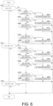
- FIG. 6 is a flowchart illustrating an example of the procedure of the charging control process for the high-voltage battery 110 performed by the VCM 10.
- the procedure illustrated in FIG. 6 is an example obtained by modifying a part of the procedure illustrated in FIG. 5 , and regarding a part common to the procedure illustrated in FIG. 5 , a part of the description thereof is omitted.
- FIG. 5 illustrates an example in which the maximum charging current value is set using the two determination references (the BT2 and the BT4 after step S221, and the BT3 and the BT5 after step S227) after the determination process for the SOH (step S221 and step S227).
- FIG. 6 illustrates an example in which the maximum charging current value is set using a plurality of determination references (the BT2 to the BT13) after the determination processes for the SOH (steps S241 and S251).
- step S241 a case is assumed where after it is determined in step S241 that the SOH of the high-voltage battery 110 is equal to or larger than the threshold value TH1, it is determined in step S244 that the temperature of the high-voltage battery 110 is equal to or higher than the BT2 and is lower than the BT4.
- step S245 the VCM 10 sets an MC1A as the maximum charging current value to the high-voltage battery 110.
- the MC1A is a value that is smaller than the MC1 and is larger than the MC2. For example, a value of about 100 A can be used as the MC1A.
- step S246 a case is assumed where it is determined in step S246 that the temperature of the high-voltage battery 110 is equal to or higher than the BT4 and is lower than the BT6.
- step S247 the VCM 10 sets an MC1B as the maximum charging current value to the high-voltage battery 110.
- the MC1B is a value that is smaller than the MC1A and is larger than the MC2. For example, a value of about 80 A can be used as the MC1B.
- step S251 a case is assumed where after it is determined in step S251 that the SOH of the high-voltage battery 110 is smaller than the threshold value TH1 and is equal to or larger than the threshold value TH2, it is determined in step S254 that the temperature of the high-voltage battery 110 is equal to or higher than the BT3 and is lower than the BT5.
- step S255 the VCM 10 sets an MC1C as the maximum charging current value to the high-voltage battery 110.
- the MC1C is a value that is smaller than the MC1B and is larger than the MC2. For example, a value of about 60 A can be used as the MC1C.
- step S248 after it is determined in step S246 that the temperature of the high-voltage battery 110 is equal to or higher than the BT6, the determination processes based on the predetermined battery temperatures and the setting processes of the maximum charging current value are repeatedly performed as in the example illustrated in FIG. 4 .
- the relation between the battery temperatures used in the determination processes in this case and the maximum charging current values set in the setting processes can be set appropriately.
- the procedure from step S247 to step S248 is omitted.
- step S258 after it is determined in step S256 that the temperature of the high-voltage battery 110 is equal to or higher than the BT6, the determination processes based on the predetermined battery temperatures and the setting processes of the maximum charging current value are repeatedly performed as in the example illustrated in FIG. 4 .
- the relation between the battery temperatures used in the determination processes in this case and the maximum charging current values set in the setting processes can also be set appropriately.
- FIG. 6 illustrates an example in which the maximum charging current value MC12 of the high-voltage battery 110 is set when it is determined in steps S248 and S258 that the temperature of the high-voltage battery 110 is higher than the BT12 and is lower than the BT13.
- FIG. 6 illustrates an example in which the charging current value 0 of the high-voltage battery 110 is set when it is determined in steps S248 and S258 that the temperature of the high-voltage battery 110 is higher than the BT13.
- a reference temperature for setting the maximum charging current value MC12 and the charging current value 0 may be set to a value lower than the BT12.
- the reference temperature may be set to a small value in accordance with a speed of the vehicle in order to avoid a limitation during traveling caused by an increase in the battery temperature due to heat generation during traveling while the vehicle is traveling.
- FIGS. 7 and 8 illustrate examples in which the timing of limiting the charging current value is advanced and traveling performance is made constant while the vehicle is traveling.
- FIG. 7 is a flowchart illustrating an example of the procedure of the charging control process for the high-voltage battery 110 performed by the VCM 10.
- the procedure illustrated in FIG. 7 is an example obtained by modifying a part of the procedure illustrated in FIG. 5 , and regarding a part common to the procedure illustrated in FIG. 5 , a part of the description thereof is omitted.
- the determination processes based on the predetermined battery temperatures and the setting processes of the maximum charging current value are repeatedly performed as in the example illustrated in FIG. 5 .
- the relation between the battery temperatures used in the determination processes in this case and the maximum charging current values set in the setting processes can be set appropriately.
- step S271 it can be determined at an early timing (the determination process of step S271) that the deterioration of the high-voltage battery 110 progresses.
- the charging current value can be limited at an early timing. Therefore, even during the traveling of the vehicle in which the battery temperature is likely to increase, the charging can be maintained, and the traveling performance can be made constant.
- FIG. 8 is a flowchart illustrating an example of the procedure of the charging control process for the high-voltage battery 110 performed by the VCM 10.
- the procedure illustrated in FIG. 8 is an example obtained by modifying a part of the procedure illustrated in FIG. 6 , and regarding a part common to the procedure illustrated in FIG. 6 , a part of the description thereof is omitted.
- FIG. 6 illustrates an example in which the threshold values BT2, BT4, and BT6 are used as the determination reference in the determination processes of the battery temperature (steps S244 and S246).
- FIG. 8 illustrates an example in which the relatively high threshold values BT2, BT5, and BT6 are used as the determination reference in the determination processes of the battery temperature (steps S304 and S306).
- FIG. 6 illustrates an example in which the threshold values BT3, BT5, and BT6 are used as the determination reference in the determination processes of the battery temperature (steps S254 and S256).
- FIG. 8 illustrates an example in which the relatively low threshold values BT2, BT3, and BT5 are used as the determination reference in the determination processes of the battery temperature (steps S314 and S316).
- FIG. 8 illustrates an example in which in the setting processes of the maximum charging current value (steps S315 and S317), the large values MC1B and MC1C are set in accordance with the small threshold values BT2, BT3, and BT5 serving as the determination reference.
- the charging current value can be limited at an early timing by using the relatively low threshold values BT2, BT3, and BT5. Therefore, even during the traveling of the vehicle in which the battery temperature is likely to increase, the charging can be maintained, and the traveling performance can be made constant.
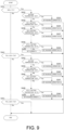
- FIG. 9 is a flowchart illustrating an example of the procedure of the charging control process for the high-voltage battery 110 performed by the VCM 10.
- the procedure illustrated in FIG. 9 is an example obtained by modifying a part of the procedure illustrated in FIG. 8 , and regarding a part common to the procedure illustrated in FIG. 8 , a part of the description thereof is omitted.
- FIG. 8 illustrates an example in which the threshold values BT2, BT5, and BT6 are used as the determination reference in the determination processes of the battery temperature (steps S302, S304, and S306) when it is determined that the high-voltage battery 110 is in the initial state.
- FIG. 8 illustrates an example in which the threshold values BT2, BT3, and BT5 are used as the determination reference in the determination processes of the battery temperature (steps S312, S314, and S316) when it is determined that the high-voltage battery 110 is in the intermediate state.
- FIG. 9 illustrates an example in which when it is determined that the high-voltage battery 110 is in the initial state, and when it is determined that the high-voltage battery 110 is in the intermediate state, the same threshold values BT2, BT4, and BT5 are used as the determination reference in the determination processes of the battery temperature (steps S332, S334, S336, S342, S344 and S346).
- the processing load on the VCM 10 can be reduced by using the same threshold values BT2, BT4, and BT5 regardless of the deteriorating state of the high-voltage battery 110. Accordingly, the charging current value can be limited at an early timing. Therefore, even during the traveling of the vehicle in which the battery temperature is likely to increase, the charging can be maintained, and the traveling performance can be made constant.
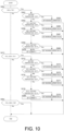
- FIG. 10 is a flowchart illustrating an example of the procedure of the charging control process for the high-voltage battery 110 performed by the VCM 10.
- the procedure illustrated in FIG. 10 is an example obtained by modifying a part of the procedure illustrated in FIG. 8 , and regarding a part common to the procedure illustrated in FIG. 8 , a part of the description thereof is omitted.
- FIG. 10 illustrates an example in which the threshold values of the battery temperature (the threshold values BT2, BT3, and BT4) when it is determined that the high-voltage battery 110 is in the intermediate state are smaller than the threshold values of the battery temperature (the threshold values BT2, BT4, and BT5) when it is determined that the high-voltage battery 110 is in the initial state, as in the example illustrated in FIG. 8 .
- FIG. 10 illustrates an example in which when it is determined that the high-voltage battery 110 is in the initial state, and when it is determined that the high-voltage battery 110 is in the intermediate state, the same maximum charging current values MC1, MC1A, and MC1B are set in the setting processes of the maximum charging current value (steps S363, S365, S367, S373, S375, and S377).
- the processing load on the VCM 10 can be reduced by using the same maximum charging current values MC1, MC1A, and MC1B regardless of the deteriorating state of the high-voltage battery 110. Accordingly, the charging current value can be limited at an early timing. Therefore, even during the traveling of the vehicle in which the battery temperature is likely to increase, the charging can be maintained, and the traveling performance can be made constant.
- the high-voltage battery 110 is likely to become high in temperature. Therefore, when such an environment or condition is satisfied, it is assumed that in order to secure the charge amount of the high-voltage battery 110, the maximum charging current value is further limited as the high-voltage battery 110 becomes high in temperature.
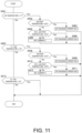
- FIG. 11 is a flowchart illustrating an example of the procedure of the charging control process for the high-voltage battery 110 performed by the VCM 10.
- the procedure illustrated in FIG. 11 is an example obtained by modifying a part of the procedure illustrated in FIG. 5 , and regarding a part common to the procedure illustrated in FIG. 5 , a part of the description thereof is omitted.
- the VCM 10 determines whether the air temperature is equal to or lower than a threshold value T1.
- the threshold value T1 is a reference value for determining whether the high-voltage battery 110 is likely to become high in temperature at the air temperature.
- the threshold value T1 is a reference value for determining that the air temperature is in a relatively low state, and for example, a value of about 20°C can be used as the threshold value T1.
- the procedure proceeds to step S402.
- the procedure proceeds to step S407.
- Processes of steps S402 to S406 are the same as the processes of steps S222 to S226 illustrated in FIG. 5 .
- the air temperature is relatively low, that is, in a case of an environment in which the high-voltage battery 110 is unlikely to become high in temperature, it is assumed that the high-voltage battery 110 is unlikely to generate heat as compared with the case where the air temperature is high, and the increase in the temperature of the high-voltage battery 110 is relatively slow. Therefore, when the temperature of the high-voltage battery 110 is lower than the BT2, the maximum charging current value is maintained or set to the charging current value MC1 corresponding to the above-described maximum charging electric power as in the example illustrated in FIG. 5 . When the temperature of the high-voltage battery 110 is equal to or higher than the BT2 and is lower than the BT4, the relatively large value MC4 is set as the maximum charging current value to the high-voltage battery 110.
- the VCM 10 determines whether the air temperature is higher than the threshold value T1 and is equal to or lower than a threshold value T2.
- the threshold value T2 is a value larger than the threshold value T1, and is a reference value for determining whether the high-voltage battery 110 is likely to become high in temperature at the air temperature.
- the threshold value T2 is a reference value for determining that the air temperature is relatively high, and for example, a value of about 30°C can be used as the threshold value T2.
- the procedure proceeds to step S408.
- the procedure proceeds to step S413.
- Processes of steps S408 to S412 are the same as the processes of steps S228 to S232 illustrated in FIG. 5 .
- the relatively low values BT3 and BT5 are used as the determination references in steps S408 and S410.
- the relatively small value MC3 is set as the maximum charging current value to the high-voltage battery 110 as in the example illustrated in FIG. 5 .
- the relatively small value MC5 is set as the maximum charging current value to the high-voltage battery 110.
- the VCM 10 determines whether the air temperature is higher than the threshold value T2 and is equal to or lower than a threshold value T3.
- the threshold value T3 is a value larger than the threshold value T2, and is a reference value for determining whether the high-voltage battery 110 is likely to become high in temperature at the air temperature.
- the threshold value T3 is a reference value for determining that the air temperature is high, and for example, a value of about 35°C can be used as the threshold value T3.
- step S413 substantially the same processes as the processes of steps S401 to S406 and S407 to S412 are performed once or a plurality of times.
- FIG. 12 is a flowchart illustrating an example of the procedure of the charging control process for the high-voltage battery 110 performed by the VCM 10.
- the procedure illustrated in FIG. 12 is an example obtained by modifying a part of the procedure illustrated in FIG. 5 , and regarding a part common to the procedure illustrated in FIG. 5 , a part of the description thereof is omitted.
- step S501 the VCM 10 determines whether the cooling system of the vehicle is operable. When the cooling system of the vehicle is operable, the procedure proceeds to step S502. On the other hand, when the entire cooling system of the vehicle is not in operation, the procedure proceeds to step S507.
- the cooling system of the vehicle is the AC 30.
- the AC 30 distributes and supplies the refrigerant to the vehicle interior for cooling and the parts other than the vehicle interior.
- the case where the cooling system of the vehicle is not operable means, for example, a case where the AC 30 fails or a case where the vehicle is present in an environment in which the cooling system cannot be operated. For example, in an environment of about -10 degrees, there is a possibility that the refrigerant is frozen and cannot be used, and thus the cooling system of the vehicle cannot be operated.
- the case where the operation of the cooling system of the vehicle is limited means a case where the AC 30 is operable, but the supply of the refrigerant to the high-voltage battery 110 is limited for certain reasons.
- the supply of the refrigerant to the high-voltage battery 110 as the cooling system is limited.
- the supply of the refrigerant to the high-voltage battery 110 as the cooling system is limited.
- Processes of steps S502 to S506 are the same as the processes of steps S222 to S226 illustrated in FIG. 5 .
- the cooling system of the vehicle when the cooling system of the vehicle is operable, that is, in the case of the environment in which the high-voltage battery 110 is unlikely to become high in temperature, it is assumed that the high-voltage battery 110 is unlikely to generate heat as compared with a case where the cooling system of the vehicle is not operable, and the increase in the temperature of the high-voltage battery 110 is relatively slow. Therefore, when the temperature of the high-voltage battery 110 is lower than the BT2, the maximum charging current value is maintained or set to the charging current value MC1 corresponding to the above-described maximum charging electric power as in the example illustrated in FIG. 5 . When the temperature of the high-voltage battery 110 is equal to or higher than the BT2 and is lower than the BT4, the relatively large value MC4 is set as the maximum charging current value to the high-voltage battery 110.
- step S507 the VCM 10 determines whether the operation of the cooling system of the vehicle is being limited. When the operation of the cooling system of the vehicle is being limited, the procedure proceeds to step S508. On the other hand, when the cooling system of the vehicle is not operable and the operation of the cooling system of the vehicle is not being limited, that is, when the cooling system of the vehicle is not operable, the procedure proceeds to step S513.
- Processes of steps S508 to S512 are the same as the processes of steps S228 to S232 illustrated in FIG. 5 .
- the relatively high values BT3 and BT5 are used as the determination references in steps S508 and S510.
- the relatively small value MC3 is set as the maximum charging current value to the high-voltage battery 110 as in FIG. 5 .
- the relatively small value MC5 is set as the maximum charging current value to the high-voltage battery 110.
- step S513 the VCM 10 determines whether the temperature of the high-voltage battery 110 is lower than the BT4. When the temperature of the high-voltage battery 110 is lower than the BT4, the procedure proceeds to step S514. On the other hand, when the temperature of the high-voltage battery 110 is equal to or higher than the BT4, the procedure proceeds to step S515.
- step S514 the VCM 10 sets the MC5 as the maximum charging current value to the high-voltage battery 110.
- step S515 the VCM 10 sets the charging current value 0 of the high-voltage battery 110.
- the relatively low value BT4 is used as the determination reference in the process of step S513. Accordingly, the charging current value 0 of the high-voltage battery 110 can be set earlier. Therefore, for example, even in an environment in which the battery temperature increases due to the heat generation while the vehicle is traveling, it is possible to avoid the limitation during the traveling.
- a battery temperature lower than the initially assumed battery temperature may be set as the determination reference, or an amount of heat generation smaller than the initially assumed amount of heat generation may be controlled to be acquired.
- FIG. 12 illustrates an example in which the maximum charging current value is set using two determination references for the battery temperature after the determination processes for the operation state of the cooling system.
- the maximum charging current value may be set using three or more determination references for the battery temperature. Therefore, FIG. 13 illustrates an example in which the maximum charging current value is set using three or more determination reference for the battery temperature after the determination process during operation limitation of the cooling system.
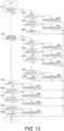
- FIG. 13 is a flowchart illustrating an example of the procedure of the charging control process for the high-voltage battery 110 performed by the VCM 10.
- the procedure illustrated in FIG. 13 is an example obtained by modifying a part of the procedure illustrated in FIG. 12 , and regarding a part common to the procedure illustrated in FIG. 12 , a part of the description thereof is omitted.
- Processes of steps S521 to S526 correspond to the processes of steps S501, S513 to S515 illustrated in FIG. 12 .
- the processes are different in that the maximum charging current values (the MC1 and the MC5) are set using the two determination references for the battery temperature (the BT2 and the BT3).
- Processes of steps S527 to S536 correspond to the processes of steps S507 to S512 illustrated in FIG. 12 .
- the processes are different in that the maximum charging current values (the MC1, the MC1B, the MC1C, ..., and the MC12) are set using the three or more determination references for the battery temperature (the BT2, the BT4, the BT6 ... the BT12, and the BT13).
- Processes of steps S537 to S545 correspond to the processes of steps S502 to S506 illustrated in FIG. 12 .
- the processes are different in that the maximum charging current values (the MC1, the MC1A, the MC1B, ..., and the MC12) are set by the three or more determination references for the battery temperature (the BT2, the BT4, the BT6, ..., the BT12, and the BT13).
- the high-voltage battery 110 is more likely to generate heat, and the increase in the temperature of the high-voltage battery 110 is also fast. Therefore, the values MC1B and MC1C smaller than set values of steps S539 and S541 are used as set values of steps S530 and S532. Accordingly, the temperature of the high-voltage battery 110 can be early set low. Therefore, for example, even in an environment in which the battery temperature increases due to the heat generation while the vehicle is traveling, it is possible to avoid the limitation during the traveling.
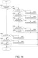
- FIGS. 12 and 13 illustrate examples in which a determination process of determining whether the operation of the cooling system is being limited is executed. However, the determination process of determining whether the operation of the cooling system is being limited may be omitted. Therefore, FIG. 14 illustrates an example in which the determination process of determining whether the operation of the cooling system is being limited is omitted.
- FIG. 14 is a flowchart illustrating an example of the procedure of the charging control process for the high-voltage battery 110 performed by the VCM 10.
- the procedure illustrated in FIG. 14 is an example obtained by modifying a part of the procedure illustrated in FIG. 12 , and regarding a part common to the procedure illustrated in FIG. 12 , a part of the description thereof is omitted.
- Processes of steps S551 to S560 correspond to the processes of steps S501 to S506 illustrated in FIG. 12 .
- the processes are different in that the maximum charging current values (the MC1, the MC1A, the MC1B ... and the MC12) are set using the three or more determination references for the battery temperature (the BT2, the BT4, the BT6, ..., the BT12, and the BT13).
- Processes of steps S561 to S565 correspond to the processes of steps S513 to S515 illustrated in FIG. 12 . However, the processes are different in that the maximum charging current values (the MC1 and the MC5) are set using the two determination references for the battery temperature (the BT2 and the BT3).
- the determination process of determining whether the operation of the cooling system is being limited is omitted, and the determination references for the battery temperature when the cooling system of the vehicle is not operable are set to relatively low values (the BT2 and the BT3). Accordingly, the temperature of the high-voltage battery 110 can be early set low. Therefore, for example, even in an environment in which the battery temperature increases due to the heat generation while the vehicle is traveling, it is possible to avoid the limitation during the traveling.
- FIGS. 4 to 14 illustrate examples in which the charging current value is controlled using the temperature of the high-voltage battery 110, the SOH of the high-voltage battery 110, the outside air temperature, and the operation state of the cooling system of the vehicle as information on heat of the high-voltage battery 110.
- FIGS. 15 and 16 illustrate examples in which the charging current value is controlled using the other information.
- FIG. 15 illustrates an example in which the charging current value is controlled using the amount of heat generation by the high-voltage battery 110 as the information on the heat of the high-voltage battery 110.
- FIG. 15 is a flowchart illustrating an example of the procedure of the charging control process for the high-voltage battery 110 performed by the VCM 10.
- the procedure illustrated in FIG. 15 is an example obtained by modifying a part of the procedure illustrated in FIG. 4 , and regarding a part common to the procedure illustrated in FIG. 4 , a part of the description thereof is omitted.
- steps S602, S604, S606, S608, S610, S611 to S614 illustrated in FIG. 15 correspond to steps S202, S204, S206, S208, S210, S211 to S214 illustrated in FIG. 4 , and thus the description thereof is omitted.
- Threshold values A1 to A5 illustrated in FIG. 15 are reference values to be used when setting the maximum charging current value.
- the A1 is a value of about 400 (J)
- the A2 is a value of about 800 (J)
- the A3 is a value of about 1200 (J)
- the A4 is a value of about 1500 (J)
- the A5 is a value of about 2000 (J).
- step S601 the VCM 10 determines whether the amount of heat generation by the high-voltage battery 110 is equal to or less than the A1.
- the amount of heat generation [W] by the high-voltage battery 110 can be obtained by using the following equation.
- Amount of Heat Generation W Internal Resistance ⁇ of High-voltage Battery 100 ⁇ Current I 2
- step S203 the procedure proceeds to step S203.
- step S603 the VCM 10 determines whether the amount of heat generation by the high-voltage battery 110 is larger than the A1 and is equal to or less than the A2.
- step S604. the procedure proceeds to step S605.
- step S605 the VCM 10 determines whether the amount of heat generation by the high-voltage battery 110 is larger than the A2 and is equal to or less than the A3.
- step S606 the procedure proceeds to step S607.
- step S607 the VCM 10 determines whether the amount of heat generation by the high-voltage battery 110 is larger than the A3 and is equal to or less than the A4.
- step S608 the procedure proceeds to step S608.
- step S609 the VCM 10 determines whether the amount of heat generation by the high-voltage battery 110 is larger than the A4 and is equal to or less than the A5. When the amount of heat generation by the high-voltage battery 110 is larger than the A4 and is equal to or less than the A5, the procedure proceeds to step S610.
- step S609 when the amount of heat generation by the high-voltage battery 110 is larger than the A5, a process based on an example of an relation between the amount of heat generation by the high-voltage battery 110 and the maximum charging current value is repeatedly performed as in the processes illustrated in steps S601 to S610, although not illustrated.
- step S614 instead of determining whether the temperature of the high-voltage battery 110 is equal to or lower than the predetermined value BT0, it may be determined whether the amount of heat generation by the high-voltage battery 110 is equal to or less than a predetermined value A0.
- a predetermined value A0 For example, a value smaller than the A1 can be used as the predetermined value A0 to be used in this case.
- a value obtained by subtracting a value corresponding to the hysteresis portion from the A1 can be set as the predetermined value A0.
- the charging current value according to the temperature of the high-voltage battery 110 can be set to a current value that can be adapted to various conditions, for example, the SOH, the outside air temperature, and the operation state of the cooling system of the vehicle. In this way, according to the present embodiment, it is possible to set an appropriate charging current limitation according to the various conditions.
- FIG. 15 illustrates the example in which the charging current value is controlled using the amount of heat generation by the high-voltage battery 110 as the information on the heat of the high-voltage battery 110.
- the amount of heat dissipation from the high-voltage battery 110 is larger than the amount of heat generation, the temperature of the high-voltage battery 110 increases. Therefore, it becomes important to calculate how to reduce the amount of heat generation by the high-voltage battery 110, and appropriately control the amount of heat generation. Therefore, FIG. 16 illustrates an example in which the charging current value is controlled using the amount of heat dissipation from the high-voltage battery 110 as the information on the heat of the high-voltage battery 110.
- FIG. 16 is a flowchart illustrating an example of the procedure of the charging control process for the high-voltage battery 110 performed by the VCM 10.
- the procedure illustrated in FIG. 16 is an example obtained by modifying a part of the procedure illustrated in FIG. 15 , and regarding a part common to the procedure illustrated in FIG. 15 , a part of the description thereof is omitted.
- steps S601, S603, S605, S607, and S609 illustrated in FIG. 15 the determination is performed using the amount of heat generation
- the determination processes of steps S621, S623, S625, S627, and S629 illustrated in FIG. 16 are different in that the determination is performed using the amount of heat dissipation.
- the amount of heat dissipation [W] from the high-voltage battery 110 can be obtained based on a relation between the temperature of the high-voltage battery 110 and a temperature of the refrigerant supplied from the AC 30.
- the amount of heat dissipation [W] from the high-voltage battery 110 can be obtained by using the following equation.
- Amount of Heat Dissipation W Temperature ° C of High-voltage Battery 110 ⁇ Temperature ° C of Refrigerant / Thermal Resistance K / W of High-voltage Battery 110
- the thermal resistance of the high-voltage battery 110 when the thermal resistance of the high-voltage battery 110 is 0.05 K/W, the amount of heat dissipation [W] is 1000 W.
- the amount of heat generation by the high-voltage battery 110 is 1562.5 W and the amount of heat dissipation is 1000 W, the temperature of the high-voltage battery 110 increases by a heat amount of 562.5 W.
- the battery temperature increases, a value obtained by "the temperature [°C] of the high-voltage battery 110 - the temperature [°C] of the refrigerant" increases accordingly, and the amount of heat dissipation also increases. In this case, the battery temperature increases to a value at which the amount of heat dissipation and the amount of heat generation are balanced.
- Threshold values B1 to B5 illustrated in FIG. 16 are reference values to be used when setting the maximum charging current value.
- the B1 is a value of about 2000 (J)
- the B2 is a value of about 1500 (J)
- the B3 is a value of about 1200 (J)
- the B4 is a value of about 800 (J)
- the B5 is a value of about 400 (J).
- step S629 when the amount of heat generation by the high-voltage battery 110 is smaller than the B5, a process based on an example of a relation between the amount of heat dissipation from the high-voltage battery 110 and the maximum charging current value is repeatedly performed as in the processes illustrated in steps S621 to S630, although not illustrated.
- step S634 instead of determining whether the temperature of the high-voltage battery 110 is equal to or lower than the predetermined value BT0, it may be determined whether the amount of heat dissipation from the high-voltage battery 110 is equal to or larger than a predetermined value B0.
- a predetermined value B0 a value larger than the B1 can be used as the predetermined value B0 to be used in this case.
- a value obtained by adding a value corresponding to the hysteresis portion to the B1 can be set as the predetermined value B0.
- the charging current value according to the temperature of the high-voltage battery 110 can be set to a current value that can be adapted to various conditions, for example, the SOH, the outside air temperature, and the operation state of the cooling system of the vehicle. In this way, according to the present embodiment, it is possible to set an appropriate charging current limitation according to the various conditions.
- the determination references and the maximum charging current values illustrated in FIGS. 4 to 16 can be appropriately changed, and the conditions illustrated in FIGS. 4 to 16 can also be used in combination. In this case, for example, when different conditions for setting the maximum charging current value are satisfied at the same time, it is preferable to set a maximum charging current value corresponding to a condition with a severest limitation among the maximum charging current values corresponding to the satisfied conditions.
- the example illustrated in FIG. 15 an example in which the amount of heat generation is used as the determination reference is illustrated. Since the amount of heat generation can be obtained based on a relation between the internal resistance of the high-voltage battery 110 and the current, the example illustrated in FIG. 15 can also be understood as an example in which the current is used as the determination reference. In addition, if the electric power and the voltage during the charging are known, the current during the charging can also be obtained. Therefore, the example illustrated in FIG. 15 can also be understood as an example in which the voltage, for example, the total voltage or a cell voltage are used as the determination reference.
- the charging current value it is possible to simply control the charging current value to keep a predetermined battery temperature range (for example, the n-th threshold value temperature to the travel output limiting temperature) instead of the control of stopping the charging when the battery temperature exceeds the threshold value temperature and restarting the charging when the battery temperature is lower than the threshold value temperature.
- a predetermined battery temperature range for example, the n-th threshold value temperature to the travel output limiting temperature
- the charging can be performed by restarting an energizing current.
- the charging current in the low-temperature region where the battery temperature is low, the charging current can be set to the charging current value MC1 corresponding to the rated charging electric power determined in accordance with the design of the external charger or the like, and high charging electric power can be secured.
- a maximum charging current is limited to control the amount of heat generation by the secondary battery and the battery temperature to the predetermined values. Accordingly, it is possible to limit an excessive increase in the battery temperature at the end of the charging, and to increase a distance by which the vehicle can travel without a discharging electric power limitation.
- the high-voltage battery 110 can be appropriately charged by appropriately controlling the amount of heat generation by the high-voltage battery 110, and the distance by which the vehicle can travel can be increased.
- the VCM 10 acquires the temperature, the current, the total voltage, the cell voltage, the state of charge, the deteriorating state, and the cooling state of the high-voltage battery 110. Further, the VCM 10 controls the energizing current at the time of charging the high-voltage battery 110 based on the temperature, the current, the total voltage, the cell voltage, the state of charge, and the deteriorating state. In this case, the VCM 10 controls the charging current value to a predetermined value, controls the battery temperature to a predetermined value, and controls the amount of heat generation by the high-voltage battery 110 to a predetermined value. In addition, the VCM 10 controls the charging electric power to be variable in order to control the charging current value to the predetermined value. When the battery temperature exceeds the predetermined value, the VCM 10 further controls to change the current value and the amount of heat generation.
- the VCM 10 controls the amount of the heat generation by the high-voltage battery 110 to the predetermined value based on at least one of the temperature, the current, the total voltage, the cell voltage, the state of charge, and the cooling state of the high-voltage battery 110, or a plurality of conditions thereof.
- the VCM 10 can control the amount of the heat generation by the high-voltage battery 110 to the predetermined value by using the constant map set in advance (see FIG. 3B ) in order to control the amount of heat generation or the battery temperature to the predetermined value.
- the VCM 10 controls the charging current value to the predetermined value based on at least one of the temperature, the current, the total voltage, the cell voltage, and the state of charge of the high-voltage battery 110, or a plurality of conditions thereof.
- the VCM 10 can change the predetermined temperature, which is a target temperature, in accordance with a difference in a heat generation condition of the high-voltage battery 110, such as the deterioration of the high-voltage battery 110 and the operation state of the cooling system of the high-voltage battery 110, and can control the temperature of the high-voltage battery 110 to the predetermined value by using the constant map set in advance (see FIG. 3B ). Accordingly, the battery temperature can be controlled to the predetermined value, and the amount of heat generation by the high-voltage battery 110 can be controlled to the predetermined value.
- the difference in the cooling performance of the cooling system for the high-voltage battery 110 occurs due to the temperature of the external environment or a difference in the amount of heat dissipation from the high-voltage battery 110. Therefore, the VCM 10 controls the charging current value to the predetermined value based on the operation state of the cooling system for the high-voltage battery 110, the temperature of the external environment, and the like. Accordingly, the battery temperature can be controlled to the predetermined value, and the amount of heat generation by the high-voltage battery 110 can be controlled to the predetermined value.
- the charging control method for a secondary battery is a charging control method for controlling the charging of the high-voltage battery 110 (an example of the secondary battery).
- the charging control method includes an acquisition step of acquiring information on the heat of the high-voltage battery 110, and a control step of setting, based on the information on the heat of the high-voltage battery 110, the charging current value of the high-voltage battery 110 to control the amount of heat generation by the high-voltage battery 110 to the predetermined value (the processes illustrated in FIGS. 4 to 16 ).
- the charging control method it is possible to set an appropriate charging current value in consideration of the amount of heat generation by the high-voltage battery 110, and it is possible to limit the increase in the temperature of the high-voltage battery 110 during the charging. Accordingly, it is possible to continuously execute the charging while limiting the increase in the temperature of the high-voltage battery 110.
- the charging electric power of the high-voltage battery 110 is set variable so that the charging current value of the high-voltage battery 110 is constant.
- a specific control configuration for adjusting the amount of heat generation by the high-voltage battery 110 to be constant is achieved. More specifically, the charging current value directly related to the amount of heat generation by the high-voltage battery 110 is set to a constant value.
- the constant values the MC1, the MC2, ..., the MC12
- the BT1 to the BT2 the BT2 to the BT3, ..., and the BT12 to the BT13, which are temperature regions
- the information on the heat of the high-voltage battery 110 is acquired at a predetermined timing.
- the VCM 10 acquires various kinds of information (an example of the information on the heat of the high-voltage battery 110) to be used for the charging control at the predetermined timing.
- the predetermined timing can be set as, for example, a start timing of the procedure to be repeatedly executed at a predetermined interval (the procedures illustrated in FIGS. 4 to 16 ) after the charging of the high-voltage battery 110 is started. Other periodic or irregular timings may be set as the predetermined timing.
- the charging current value of the high-voltage battery 110 is changed based on the change.
- the predetermined change is detected, for example, in the determination processes illustrated in FIGS. 4 to 16 .
- the battery temperature lower than the BT2 is equal to or higher than the BT2 (No in step S201)
- it is detected that a predetermined change in the battery temperature (an example of the information on the heat of the high-voltage battery 110) occurred.
- the charging current value of the high-voltage battery 110 is changed based on the change. For example, when the battery temperature is equal to or higher than the BT2 and is lower than the BT3, the charging current value of the high-voltage battery 110 is changed from the MC2 to the MC3.
- the charging current value is changed based on the change, and thus the charging current value can be set quickly in consideration of the amount of heat generation by the high-voltage battery 110.
- the information on the heat of the high-voltage battery 110 can be at least one of the temperature of the high-voltage battery 110, the amount of heat generation by the high-voltage battery 110, and the amount of heat dissipation from the high-voltage battery 110.
- the information on the heat of the high-voltage battery 110 can be quantified by a parameter that can be detected or calculated relatively easily, such as the temperature of the high-voltage battery 110, the amount of heat generation by the high-voltage battery 110, and the amount of heat dissipation from the high-voltage battery 110. Therefore, a preferable control configuration for appropriately setting the charging current value in consideration of the heat generation by the high-voltage battery 110 is achieved.
- the information on the heat of the high-voltage battery 110 can include the external environment of the high-voltage battery 110 or the deteriorating state of the high-voltage battery 110.
- the charging current value of the high-voltage battery 110 is set using the external environment of the high-voltage battery 110 or the deteriorating state of the high-voltage battery 110 together with at least one of the temperature of the high-voltage battery 110, the amount of heat generation by the high-voltage battery 110, and the amount of heat dissipation from the high-voltage battery 110.
- the charging control method it is possible to set an appropriate charging current value in consideration of the amount of heat generation by the high-voltage battery 110 using the external environment of the high-voltage battery 110 or the deteriorating state of the high-voltage battery 110.
- the determination reference for setting the charging current value of the high-voltage battery 110 is changed based on the external environment of the high-voltage battery 110 or the deteriorating state of the high-voltage battery 110.
- the charging control method since the determination reference for setting the charging current value of the high-voltage battery 110 is changed based on the external environment of the high-voltage battery 110 or the like, it is possible to set an appropriate charging current value in consideration of the amount of heat generation by the high-voltage battery 110.
- the external environment of the high-voltage battery 110 can be set to the external temperature of the high-voltage battery 110, or the operation state of the cooling system for the high-voltage battery 110.
- the charging control method it is possible to set an appropriate charging current value in consideration of the amount of heat generation by the high-voltage battery 110 based on the external temperature of the high-voltage battery 110 or the operation state of the cooling system for the high-voltage battery 110.
- the control system for secondary battery 1 is a charging control system that includes the high-voltage battery 110 (an example of the secondary battery) and the VCM 10 that controls the charging of the high-voltage battery 110 (an example of the controller).
- the VCM 10 acquires the information on the heat of the high-voltage battery 110, and sets, based on the information on the heat of the high-voltage battery 110, the charging current value of the high-voltage battery 110 to control the amount of the heat generation by the high-voltage battery 110 to the predetermined value.
- control system for secondary battery 1 it is possible to set an appropriate charging current value in consideration of the amount of heat generation by the high-voltage battery 110, and it is possible to limit the increase in the temperature of the high-voltage battery 110 during the charging. Accordingly, it is possible to continuously execute the charging while limiting the increase in the temperature of the high-voltage battery 110.
- each process described in the present embodiment is executed based on a program that causes a computer to execute each procedure. Therefore, the present embodiment can be understood as an embodiment of a program that implements a function of executing each process and a recording medium that stores the program.
- the program can be stored in a storage device of the vehicle by an update operation for adding a new function to the vehicle. Accordingly, each process described in the present embodiment can be executed on the updated vehicle.
- the update may be performed, for example, at the time of a periodic inspection of the vehicle.
- the program may also be updated by wireless communication.
Landscapes
- Engineering & Computer Science (AREA)
- Manufacturing & Machinery (AREA)
- Chemical & Material Sciences (AREA)
- Chemical Kinetics & Catalysis (AREA)
- Electrochemistry (AREA)
- General Chemical & Material Sciences (AREA)
- Power Engineering (AREA)
- Automation & Control Theory (AREA)
- Charge And Discharge Circuits For Batteries Or The Like (AREA)
- Secondary Cells (AREA)
Applications Claiming Priority (1)
| Application Number | Priority Date | Filing Date | Title |
|---|---|---|---|
| PCT/JP2020/047776 WO2022137306A1 (fr) | 2020-12-21 | 2020-12-21 | Procédé de commande de charge et système de commande de charge |
Publications (2)
| Publication Number | Publication Date |
|---|---|
| EP4266448A1 true EP4266448A1 (fr) | 2023-10-25 |
| EP4266448A4 EP4266448A4 (fr) | 2024-03-13 |
Family
ID=82159111
Family Applications (1)
| Application Number | Title | Priority Date | Filing Date |
|---|---|---|---|
| EP20966179.2A Pending EP4266448A4 (fr) | 2020-12-21 | 2020-12-21 | Procédé de commande de charge et système de commande de charge |
Country Status (6)
| Country | Link |
|---|---|
| US (1) | US20240039322A1 (fr) |
| EP (1) | EP4266448A4 (fr) |
| JP (1) | JP7556408B2 (fr) |
| CN (1) | CN116636065A (fr) |
| MX (1) | MX2023007392A (fr) |
| WO (1) | WO2022137306A1 (fr) |
Families Citing this family (3)
| Publication number | Priority date | Publication date | Assignee | Title |
|---|---|---|---|---|
| AU2022225747A1 (en) * | 2021-02-23 | 2023-05-25 | Zodiac Pool Care Europe | Wireless automatic swimming pool cleaners and associated systems and methods |
| CN119116719B (zh) * | 2024-08-15 | 2025-10-28 | 东风汽车集团股份有限公司 | 自动热平衡充电方法、装置、设备、存储介质及产品 |
| CN119628146B (zh) * | 2024-11-25 | 2025-09-09 | 深圳市瑞亨数字能源科技有限公司 | 充放电控制方法、装置、计算机装置和存储装置 |
Family Cites Families (14)
| Publication number | Priority date | Publication date | Assignee | Title |
|---|---|---|---|---|
| JP3509382B2 (ja) * | 1995-04-27 | 2004-03-22 | 日産自動車株式会社 | 充電制御システム |
| JP3695266B2 (ja) * | 1999-12-03 | 2005-09-14 | 日立工機株式会社 | 満充電判別方法 |
| JP2002343449A (ja) | 2001-05-16 | 2002-11-29 | Nissan Motor Co Ltd | 冷却装置の故障判断装置 |
| JP4085903B2 (ja) * | 2003-07-11 | 2008-05-14 | 日立工機株式会社 | 充電機能付き直流電源装置 |
| JP2005276733A (ja) * | 2004-03-26 | 2005-10-06 | Hitachi Koki Co Ltd | 充電装置 |
| JP4275078B2 (ja) | 2005-01-13 | 2009-06-10 | 三洋電機株式会社 | 電池の制限電流制御方法 |
| JP4715803B2 (ja) | 2007-05-07 | 2011-07-06 | トヨタ自動車株式会社 | 二次電池冷却装置 |
| JP2009207312A (ja) * | 2008-02-28 | 2009-09-10 | Sanyo Electric Co Ltd | 車両用の電源装置とその電流制御方法 |
| JP5696377B2 (ja) | 2010-06-11 | 2015-04-08 | トヨタ自動車株式会社 | 車両用制御装置および車両用制御方法 |
| JP2013031303A (ja) | 2011-07-28 | 2013-02-07 | Sanyo Electric Co Ltd | 電池パックの無接点充電方法及び電池パック |
| JP5819443B2 (ja) * | 2011-12-22 | 2015-11-24 | 日立オートモティブシステムズ株式会社 | 電池制御装置、電池システム |
| JP5959783B1 (ja) * | 2015-01-16 | 2016-08-02 | 三菱電機株式会社 | 電力管理装置 |
| KR102507229B1 (ko) * | 2017-12-05 | 2023-03-08 | 현대자동차주식회사 | 차량용 배터리 냉각시스템 및 제어방법 |
| CN112292782B (zh) * | 2018-06-22 | 2024-09-17 | 松下知识产权经营株式会社 | 电池系统 |
-
2020
- 2020-12-21 JP JP2022570791A patent/JP7556408B2/ja active Active
- 2020-12-21 CN CN202080108110.3A patent/CN116636065A/zh active Pending
- 2020-12-21 WO PCT/JP2020/047776 patent/WO2022137306A1/fr not_active Ceased
- 2020-12-21 EP EP20966179.2A patent/EP4266448A4/fr active Pending
- 2020-12-21 MX MX2023007392A patent/MX2023007392A/es unknown
- 2020-12-21 US US18/268,525 patent/US20240039322A1/en active Pending
Also Published As
| Publication number | Publication date |
|---|---|
| EP4266448A4 (fr) | 2024-03-13 |
| JP7556408B2 (ja) | 2024-09-27 |
| US20240039322A1 (en) | 2024-02-01 |
| JPWO2022137306A1 (fr) | 2022-06-30 |
| MX2023007392A (es) | 2023-07-05 |
| WO2022137306A1 (fr) | 2022-06-30 |
| CN116636065A (zh) | 2023-08-22 |
Similar Documents
| Publication | Publication Date | Title |
|---|---|---|
| EP4266448A1 (fr) | Procédé de commande de charge et système de commande de charge | |
| US5982152A (en) | Battery charging apparatus | |
| US9425647B2 (en) | Charging-control apparatus and charging-control method | |
| EP2670018B1 (fr) | Système de batterie de véhicule électrique | |
| KR20220062225A (ko) | 차량 배터리 관리 시스템 및 방법 | |
| US20140103859A1 (en) | Electric storage system | |
| US20030178970A1 (en) | Battery control device | |
| KR20190000445A (ko) | 전기자동차용 배터리의 열화 발생을 저감하면서 고속충전과 최대방전을 수행하기 위한 방법 및 그 장치 | |
| US20180093581A1 (en) | Power supply device for vehicle | |
| JP5821669B2 (ja) | 推定装置、推定方法および制御方法 | |
| JP2019187027A (ja) | 蓄電装置 | |
| JP7420232B2 (ja) | 二次電池の出力制御方法及び二次電池の出力制御システム | |
| CN111746346B (zh) | 电源系统 | |
| JP2019004565A (ja) | 蓄電池制御装置 | |
| JP4805328B2 (ja) | 電動車両 | |
| KR20140014715A (ko) | 차량용 배터리의 제어 방법 | |
| JP2008236951A (ja) | 鉛バッテリの充電制御装置 | |
| EP4324689A1 (fr) | Procédé de commande de couple et système de commande de couple pour système d'entraînement électrique | |
| EP4379994B1 (fr) | Dispositif de batterie comprenant un système de gestion de batterie | |
| JP2023154861A (ja) | 二次電池の制御装置、および、二次電池の満充電容量推定方法 | |
| CN113400945A (zh) | 纯电动汽车能量回收控制方法 | |
| KR20230077819A (ko) | 차량 제어 장치 그 제어 방법 | |
| US12485792B2 (en) | System and method for active energy management for an electric vehicle | |
| EP4395110A1 (fr) | Procédé et appareil de charge, et dispositif électronique et support de stockage | |
| CN114633665B (zh) | 充电控制装置 |
Legal Events
| Date | Code | Title | Description |
|---|---|---|---|
| STAA | Information on the status of an ep patent application or granted ep patent |
Free format text: STATUS: UNKNOWN |
|
| STAA | Information on the status of an ep patent application or granted ep patent |
Free format text: STATUS: THE INTERNATIONAL PUBLICATION HAS BEEN MADE |
|
| PUAI | Public reference made under article 153(3) epc to a published international application that has entered the european phase |
Free format text: ORIGINAL CODE: 0009012 |
|
| STAA | Information on the status of an ep patent application or granted ep patent |
Free format text: STATUS: REQUEST FOR EXAMINATION WAS MADE |
|
| 17P | Request for examination filed |
Effective date: 20230718 |
|
| AK | Designated contracting states |
Kind code of ref document: A1 Designated state(s): AL AT BE BG CH CY CZ DE DK EE ES FI FR GB GR HR HU IE IS IT LI LT LU LV MC MK MT NL NO PL PT RO RS SE SI SK SM TR |
|
| REG | Reference to a national code |
Ref country code: DE Ref legal event code: R079 Free format text: PREVIOUS MAIN CLASS: H01M0010440000 Ipc: H02J0007000000 |
|
| A4 | Supplementary search report drawn up and despatched |
Effective date: 20240212 |
|
| RIC1 | Information provided on ipc code assigned before grant |
Ipc: H02J 7/00 20060101AFI20240206BHEP |
|
| DAV | Request for validation of the european patent (deleted) | ||
| DAX | Request for extension of the european patent (deleted) |