EP4266543A1 - Dispositif de transmission d'énergie, dispositif de réception d'énergie, leurs procédés de commande et programme - Google Patents
Dispositif de transmission d'énergie, dispositif de réception d'énergie, leurs procédés de commande et programme Download PDFInfo
- Publication number
- EP4266543A1 EP4266543A1 EP21906142.1A EP21906142A EP4266543A1 EP 4266543 A1 EP4266543 A1 EP 4266543A1 EP 21906142 A EP21906142 A EP 21906142A EP 4266543 A1 EP4266543 A1 EP 4266543A1
- Authority
- EP
- European Patent Office
- Prior art keywords
- power transmission
- power
- power reception
- reception apparatus
- communication means
- Prior art date
- Legal status (The legal status is an assumption and is not a legal conclusion. Google has not performed a legal analysis and makes no representation as to the accuracy of the status listed.)
- Withdrawn
Links
Images





Classifications
-
- H—ELECTRICITY
- H02—GENERATION; CONVERSION OR DISTRIBUTION OF ELECTRIC POWER
- H02J—ELECTRIC POWER NETWORKS; CIRCUIT ARRANGEMENTS OR SYSTEMS FOR SUPPLYING OR DISTRIBUTING ELECTRIC POWER; SYSTEMS FOR STORING ELECTRIC ENERGY
- H02J50/00—Circuit arrangements or systems for wireless supply or distribution of electric power
- H02J50/80—Circuit arrangements or systems for wireless supply or distribution of electric power involving the exchange of data, concerning supply or distribution of electric power, between transmitting devices and receiving devices
-
- H—ELECTRICITY
- H02—GENERATION; CONVERSION OR DISTRIBUTION OF ELECTRIC POWER
- H02J—ELECTRIC POWER NETWORKS; CIRCUIT ARRANGEMENTS OR SYSTEMS FOR SUPPLYING OR DISTRIBUTING ELECTRIC POWER; SYSTEMS FOR STORING ELECTRIC ENERGY
- H02J50/00—Circuit arrangements or systems for wireless supply or distribution of electric power
- H02J50/90—Circuit arrangements or systems for wireless supply or distribution of electric power involving detection or optimisation of position, e.g. alignment
-
- H—ELECTRICITY
- H04—ELECTRIC COMMUNICATION TECHNIQUE
- H04B—TRANSMISSION
- H04B5/00—Near-field transmission systems, e.g. inductive or capacitive transmission systems
- H04B5/20—Near-field transmission systems, e.g. inductive or capacitive transmission systems characterised by the transmission technique; characterised by the transmission medium
- H04B5/24—Inductive coupling
- H04B5/26—Inductive coupling using coils
-
- H—ELECTRICITY
- H04—ELECTRIC COMMUNICATION TECHNIQUE
- H04B—TRANSMISSION
- H04B5/00—Near-field transmission systems, e.g. inductive or capacitive transmission systems
- H04B5/70—Near-field transmission systems, e.g. inductive or capacitive transmission systems specially adapted for specific purposes
- H04B5/79—Near-field transmission systems, e.g. inductive or capacitive transmission systems specially adapted for specific purposes for data transfer in combination with power transfer
-
- H—ELECTRICITY
- H02—GENERATION; CONVERSION OR DISTRIBUTION OF ELECTRIC POWER
- H02J—ELECTRIC POWER NETWORKS; CIRCUIT ARRANGEMENTS OR SYSTEMS FOR SUPPLYING OR DISTRIBUTING ELECTRIC POWER; SYSTEMS FOR STORING ELECTRIC ENERGY
- H02J50/00—Circuit arrangements or systems for wireless supply or distribution of electric power
- H02J50/10—Circuit arrangements or systems for wireless supply or distribution of electric power using inductive coupling
-
- H—ELECTRICITY
- H02—GENERATION; CONVERSION OR DISTRIBUTION OF ELECTRIC POWER
- H02J—ELECTRIC POWER NETWORKS; CIRCUIT ARRANGEMENTS OR SYSTEMS FOR SUPPLYING OR DISTRIBUTING ELECTRIC POWER; SYSTEMS FOR STORING ELECTRIC ENERGY
- H02J50/00—Circuit arrangements or systems for wireless supply or distribution of electric power
- H02J50/60—Circuit arrangements or systems for wireless supply or distribution of electric power responsive to the presence of foreign objects, e.g. detection of living beings
Definitions
- the present invention relates to wireless power transmission technology.
- PTL1 discloses a power transmission apparatus and a power reception apparatus that comply with a standard (WPC standard) established by the Wireless Power Consortium (WPC), which is a consortium working toward the standardization of wireless power transmission standards.
- WPC Wireless Power Consortium
- PTL2 discloses a technique in which, in a wireless power transmission system, control signals for power transmission/reception are transmitted and received using a frequency or coil/antenna different from the frequency or coil/antenna used for power transmission/reception.
- in-band communication communication performed using the frequency or coil/antenna used for power transmission/reception
- out-band communication communication performed using a frequency or coil/antenna different from the frequency or coil/antenna used for power transmission/reception
- the WPC standard power transmission/reception and control communication therefor are performed via magnetic induction. Furthermore, a power transmission apparatus and a power reception apparatus complying with the WPC standard perform control communication using the same frequency as that used for power transmission/reception. In other words, the control communication is in-band communication. Generally, with in-band communication, the communication range in which communication can be performed without errors is smaller compared to that with out-band communication. Conventionally, no investigation has been carried out regarding appropriate control of communication between a power transmission apparatus and a power reception apparatus that can execute both in-band communication and out-band communication.
- the present invention has been made in view of the above-mentioned problem, and an aim thereof is to provide a technique for appropriately controlling communication between a power transmission apparatus and a power reception apparatus that can execute both in-band communication and out-band communication.
- communication between a power transmission apparatus and a power reception apparatus that can execute both in-band communication and out-band communication can be controlled appropriately.
- FIG. 1 illustrates an example configuration of a wireless power transmission system according to the present embodiment.
- the present wireless power transmission system is configured to include a power transmission apparatus 100 and a power reception apparatus 101.
- the power transmission apparatus 100 and the power reception apparatus 101 each have the function of communicating via Bluetooth (registered trademark) Low Energy (BLE).
- BLE Bluetooth Low Energy
- a BLE communication unit (unit constituted by a communication circuit or the like) may be referred to as "BLE”.
- the power transmission apparatus 100 functions as a BLE central
- the power reception apparatus 101 functions as a BLE peripheral
- "Central" indicates a BLE control station
- "peripheral” indicates a BLE terminal station.
- ABLE central performs communication with a BLE peripheral, and does not perform communication with other centrals.
- a BLE peripheral performs communication with a BLE central, but does not perform communication with other peripherals. That is, in BLE, centrals do not perform communication with one another, and peripherals do not perform communication with one another.
- a central can be in connection state (BLE CONNECT state) with a plurality of peripherals, and can transmit and receive data to and from a plurality of peripherals.
- the power transmission apparatus 100 and the power reception apparatus 101 may be configured so to be built into other devices (cameras, smartphones, tablet PCs, laptops, automobiles, robots, medical devices, printers) and to supply power to such devices.
- FIG. 2 is a block diagram illustrating an example configuration of the power transmission apparatus 100.
- the power transmission apparatus 100 includes a control unit 201, a power supply unit 202, a power transmission unit 203, a first communication unit 204, a power transmission coil 205, a second communication unit 206, and a memory 207.
- the control unit 201 controls the entire power transmission apparatus.
- the control unit 201 may be configured to include one or more processors such as a central processing unit (CPU) and/or a micro processing unit (MPU).
- processors such as a central processing unit (CPU) and/or a micro processing unit (MPU).
- the control unit 201 may include an application-specific integrated circuit (ASIC), a field-programmable gate array (FPGA), or the like that is configured to execute the later-described processing.
- ASIC application-specific integrated circuit
- FPGA field-programmable gate array
- the power supply unit 202 is a power supply that at least supplies power when the control unit 201 and the power transmission unit 203 operate.
- the power supply unit 202 may be a wired power reception circuit that receives power supplied from a commercial power supply, a battery, or the like.
- the power transmission unit 203 Under control by the control unit 201, the power transmission unit 203 generates an AC voltage and an AC current in the power transmission coil 205 in order to transmit power to the power reception apparatus 101 via the power transmission coil 205.
- the power transmission unit 203 converts a DC voltage supplied from the power supply unit 202 into an AC voltage using a half-bridge or full-bridge switching circuit in which a field-effect transistor (FET) is used.
- the power transmission unit 203 includes a gate driver that controls the ON and OFF of the FET.
- the first communication unit 204 performs control communication for wireless power transmission based on the WPC standard with a communication unit (first communication unit 303 illustrated in FIG. 3 ) of the power reception apparatus 101.
- the communication executed by the first communication unit 204 is so-called in-band communication in which the AC voltage or current generated by the power transmission unit 203 is modulated to superimpose communication-target data (signal) on wireless power (power that is transmitted).
- the second communication unit 206 performs control communication for wireless power transmission based on the WPC standard with a communication unit (second communication unit 304 illustrated in FIG. 3 ) of the power reception apparatus 101.
- the second communication unit 206 performs so-called out-band communication using a frequency that is different from the frequency that the power transmission unit 203 uses for communication (frequency used for power transmission) and using an unillustrated antenna that is different from the power transmission coil 205.
- Out-band communication has a higher transmission speed (communication speed) than in-band communication.
- the control of the wireless power transmission system can be performed at higher speed by using out-band communication for control communication.
- the second communication unit 206 supports BLE.
- the BLE standard defines identification information (Bluetooth device identification information: BD_ADDR) of BLE communication units (the second communication units 304 and 206 in the present embodiment) and manufacturers of products equipped with BLE.
- the identification information is represented by a Public Address or a Random Address that is determined by a random number. Random Addresses include a Static Device Address, a Resolvable Private Address, and a Non-resolvable Private Address.
- a Static Device Address is an address that is generated using a random number that is generated each time the second communication unit 304 or 206 (BLE communication unit) is turned on.
- ANon-resolvable Private Address is a random-number address that is generated each time a predetermined amount of time elapses.
- a Resolvable Private Address is an address that is generated based on an encryption key exchanged between a central and a peripheral.
- the Static Device Address among the Random Addresses is used as the identification information of the second communication unit 206.
- the identification information is not limited to being a Static Device Address, and may be a Public Address, a Resolvable Private Address, or a Non-resolvable Private Address.
- the second communication unit 206 supports BLE in the present embodiment
- a communication unit supporting another wireless communication method such as near-field communication (NFC) or WiFi, may be used in place of the second communication unit 206.
- the first communication unit 204 may have a smaller communication range than the second communication unit 206.
- the memory 207 stores the states of the elements and the entirety of the power transmission apparatus and the wireless power transmission system.
- control unit 201 the power supply unit 202, the power transmission unit 203, the first communication unit 204, the memory 207, and the second communication unit 206 are each illustrated as a separate block. However, two or more of these blocks may be integrated using a single chip or the like. Furthermore, one block may be divided into a plurality of blocks.
- FIG. 3 is a block diagram illustrating an example configuration of the power reception apparatus 101.
- the power reception apparatus 101 includes a control unit 301, a power reception unit 302, the first communication unit 303, the second communication unit 304, a power reception coil 305, a charging unit 306, a battery 307, and a memory 308.
- the control unit 301 controls the entire power reception apparatus 101.
- the control unit 301 may be configured to include one or more processors such as a CPU and/or an MPU.
- the control unit 201 may include an application-specific integrated circuit (ASIC), a field-programmable gate array (FPGA), or the like that is configured to execute the later-described processing.
- ASIC application-specific integrated circuit
- FPGA field-programmable gate array
- the power reception unit 302 obtains an AC voltage and an AC current generated in the power reception coil 305 as a result of power transmission from the power transmission coil 205, and converts the received power into a DC voltage and a DC current required for the control unit 301, the charging unit 306, etc., to operate.
- the first communication unit 303 performs control communication for wireless power transmission based on the WPC standard with the first communication unit 204 of the power transmission apparatus 100. This control communication is performed via in-band communication in which load modulation is applied to an electromagnetic wave received by the power reception coil 305.
- the second communication unit 304 performs control communication for wireless power transmission based on the WPC standard with the second communication unit 206 of the power transmission apparatus 100.
- the second communication unit 304 performs out-band communication using a frequency that is different from the frequency of the electromagnetic wave received by the power reception unit 302 and using an unillustrated antenna that is different from the power reception coil 305.
- description will be provided supposing that the second communication unit 304 supports BLE, and the Static Device Address among the Random Addresses is used as the identification information of the second communication unit 304.
- the identification information is not limited to being a Static Device Address, and may be a Public Address, a Resolvable Private Address, or a Non-resolvable Private Address.
- the second communication unit 304 supports BLE in the present embodiment, a communication unit supporting another wireless communication method, such as NFC or WiFi, may be used in place of the second communication unit 304. Furthermore, while the second communication unit 304 operates by directly receiving power supply from the power reception unit 302, the second communication unit 304 may receive power supply from the battery 307. The first communication unit 303 may have a smaller communication range than the second communication unit 304.
- the charging unit 306 charges the battery 307 using the DC voltage and the DC current supplied from the power reception unit 302.
- the memory 308 stores the states of the elements and the entirety of the power reception apparatus 101 and the wireless power transmission system.
- control unit 301 the power reception unit 302, the first communication unit 303, the second communication unit 304, the charging unit 306, and the memory 308 are each illustrated as a separate block. However, two or more of these blocks may be integrated using a single chip or the like. Furthermore, one block may be divided into a plurality of blocks.
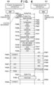
- FIG. 4 is a sequence diagram of the power transmission apparatus and the power reception apparatus.
- the basic operations of the power transmission apparatus 100 and the power reception apparatus 101 will be described with reference to part of FIG. 4 .
- the power transmission apparatus 100 and the power reception apparatus 101 in the present embodiment comply with version 1.2.3 of the WPC standard, and also support out-band communication via BLE.
- GRQ() General Request defined by the WPC standard
- SRQ() Special Request defined by the WPC standard
- the power transmission apparatus 100 transmits Analog Ping (hereinafter "A-Ping") in order to detect an object present near the power transmission coil 205 (F400).
- A-Ping is pulsed power, and is power for detecting an object. Even if the power reception apparatus 101 receives A-Ping, this power is too small to activate the control unit 301 of the power reception apparatus 101.
- the power transmission apparatus 100 detects an object based on a shift of the resonant frequency of the internal voltage value of the power transmission coil 205 and a change in the value of the current/voltage flowing in the power transmission coil 205, which occur when an object is present near the power transmission coil 205.
- the power transmission apparatus 100 Upon detecting an object using A-Ping, the power transmission apparatus 100 measures the Q factor of the power transmission coil 205 (F401). It suffices that a well-known method be used for the Q factor measurement, and detailed description thereof is thus omitted. Upon completion of the Q factor measurement, the power transmission apparatus 100 starts to transmit Digital Ping (hereinafter "D-Ping") (F402). D-Ping is power for activating the control unit 301, the second communication unit 304, etc., of the power reception apparatus 101, and is greater than A-Ping. Furthermore, D-Ping (F402) is continuously transmitted following this point.
- D-Ping Digital Ping
- the power transmission apparatus 100 continues to transmit power that is greater than or equal to D-Ping from when the transmission of D-Ping is started to when End Power Transfer (EPT) data (signal), which is a request to stop power transmission, is received from the power reception apparatus 101.
- EPT End Power Transfer
- the power reception apparatus 101 Upon receiving D-Ping and being activated, the power reception apparatus 101 transmits Signal Strength, which is data in which the voltage value of the received D-Ping is stored, to the power transmission apparatus 100 (F403). Subsequently, the power reception apparatus 101 transmits data in which is stored an ID including device identification information and the version information of the WPC standard with which the power reception apparatus 101 complies (F404). Furthermore, the power reception apparatus 101 transmits, to the power transmission apparatus 100, Configuration data including information such as the maximum value of power that the power reception unit 302 supplies to a load (i.e., the charging unit 306) (F405).
- Signal Strength which is data in which the voltage value of the received D-Ping is stored
- the power transmission apparatus 100 responds with ACK upon determining that the power reception apparatus 101 supports an extension protocol of WPC standard version 1.2 or later by receiving the ID and Configuration data (F406).
- the extension protocol is a protocol including the later-described Negotiation phase.
- the power reception apparatus 101 Upon receiving ACK, the power reception apparatus 101 transitions to the Negotiation phase, in which negotiation of power to be transmitted and received, etc., are performed. First, the power reception apparatus 101 transmits Foreign Object Detection (FOD) Status data to the power transmission apparatus 100 (F407).
- FOD Status data is indicated by "FOD(Q)”.
- the power transmission apparatus 100 performs foreign object detection based on the Q factor stored in the received FOD(Q) and the Q factor measured in the Q factor measurement (F401).
- the power transmission apparatus 100 determines that the probability is high of there being no foreign object, and, in this case, the power transmission apparatus 100 transmits, to the power reception apparatus 101, ACK indicating that it has been determined that the probability is high of there being no foreign object (F408).
- the power reception apparatus 101 Upon receiving ACK, the power reception apparatus 101 transmits GRQ(CAP) to make an inquiry of the capability of the power transmission apparatus 100 (F409).
- the power transmission apparatus 100 Upon receiving GRQ(CAP), the power transmission apparatus 100 transmits Capability data (indicated by "CAP"), in which is stored information of the capability that the power transmission apparatus 100 supports (F410).
- Guaranteed Power is the maximum value of the load power (power consumed by the charging unit 306) in the power reception apparatus 101 that is agreed upon in the negotiation between the power transmission apparatus 100 and the power reception apparatus 101.
- the power reception apparatus 101 transmits, to the power transmission apparatus 100, data (indicated by "SRQ(GP)") in which a Guaranteed Power value requested by the power reception apparatus 101 is stored (F411). Subsequently, upon receiving SRQ(GP), the power transmission apparatus 100 responds to SRQ(GP) in consideration of the power transmission capability, etc., thereof. In the present example, the power transmission apparatus 100 determines that the Guaranteed Power is acceptable, and transmits ACK indicating that the request is accepted (F412). In the present example, the power reception apparatus 101 makes a request for 15 W Guaranteed Power in SRQ(GP), and the power transmission apparatus 100 accepts this request.
- the power reception apparatus 101 notifies the power transmission apparatus 100 of the BD_ADDR (indicated by "GRQ(PRX_BD_ADDR)”) of the second communication unit 304 (F413).
- the power transmission apparatus 100 Upon receiving GRQ(PRX_BD_ADDR), the power transmission apparatus 100 responds with ACK (F414).
- the power reception apparatus 101 transmits a request (indicated by "GRQ(PTX BDADDR ADDR)" (F415)) for notification of the BD_ADDR of the second communication unit 206 of the power transmission apparatus 100 (F415).
- the power transmission apparatus 100 Upon receiving GRQ(PTX_BD_ADDR_ADDR), the power transmission apparatus 100 notifies the power reception apparatus 101 of the BD_ADDR (indicated by "PTX_BD_ADDR”) of the second communication unit 206 (F416).
- the power reception apparatus 101 transmits a request (indicated by "SRQ(CONNCT)") for establishing connection of out-band communication as the control communication (F417).
- SRQ(CONNCT) a request for establishing connection of out-band communication as the control communication
- the power transmission apparatus 100 agrees to perform out-band communication via BLE, and, in this case, transmits ACK in response to the received SRQ(CONNECT) (F418).
- the power reception apparatus 101 Upon receiving ACK, the power reception apparatus 101 transmits a request (indicated by "SRQ(EN)") for termination of the Negotiation phase (F419). Upon receiving SRQ(EN), the power transmission apparatus 100 determines whether or not the Negotiation phase can be terminated. In the present example, the power transmission apparatus 100 determines that the Negotiation phase is to be terminated, and transmits ACK (F420).
- the power reception apparatus 101 Upon receiving ACK, the power reception apparatus 101 activates the second communication unit 304 directly using the power received by the power reception unit 302, rather than using power from the battery 307. Then, the power reception apparatus 101 broadcasts ADVERTISE_INDICATION (hereinafter indicated by "ADV") using the second communication unit 304 (F421).
- ADV is a signal defined by the BLE standard.
- ADV is a signal that is broadcast by a device in the Advertiser state as defined by the BLE standard and is for providing a notification of the BD_ADDR of the device and information of services supported by the device.
- the power transmission apparatus 100 Upon transmitting ACK (F420), the power transmission apparatus 100 activates the second communication unit 206 as a Scanner and waits to receive ADV In the present example, before a predetermined period of time for which the second communication unit 206 operates as a Scanner elapses, the power transmission apparatus 100 receives, from the power reception apparatus 101, ADV including the BD_ADDR received in F413 via the in-band communication. In this case, the power transmission apparatus 100 causes the second communication unit 206 to operate as an Initiator as defined by the BLE standard. The second communication unit 206 operating as an Initiator transmits, to the received BD_ADDR, Connect_indication (hereinafter indicated by "CONNECT"), which is a BLE connection request message (F422). Following this point, the control communication between the power transmission apparatus 100 and the power reception apparatus 101 is performed via BLE (i.e., via the second communication unit 206 and the second communication unit 304).
- CONNECT Connect_indication
- the power transmission apparatus 100 and the power reception apparatus 101 perform Calibration processing in order to create references for performing foreign object detection based on the power loss method.
- the power reception apparatus 101 transmits, to the power transmission apparatus 100, Received Power Packet(mode1) (indicated by "PR1"), in which is stored a received power value R1 corresponding to when the power reception apparatus 101 receives D-Ping in a state in which the power reception unit 302 and the load are not connected and the received power is not supplied to the load (F423).
- the power transmission apparatus 100 Upon receiving RP1, the power transmission apparatus 100 transmits ACK to the power reception apparatus 101 (F424). At this time, the power transmission apparatus 100 measures a transmitted power value T1 transmitted by the power transmission apparatus 100, and calculates a difference ⁇ 1 between T1 and R1, which corresponds to power loss.
- the power reception apparatus 101 Upon receiving ACK, the power reception apparatus 101 requests the power transmission apparatus 100 to increase or decrease the received voltage (or the received current or received power) in accordance with the load, in a state in which the power reception unit 302 and the load are connected and the received power is supplied to the load.
- the request is made by transmitting Control Error (hereinafter indicated by "CE") to the power transmission apparatus 100.
- CE Control Error
- information of a sign and a numerical value is stored.
- a positive sign appended to the numerical value stored in CE indicates a request to increase the received voltage
- a negative sign appended to the numerical value stored in CE indicates a request to decrease the received voltage
- the numerical value zero stored in CE indicates a request to keep the received voltage the same.
- the power reception apparatus 101 transmits, to the power transmission apparatus 100, CE(+) indicating that the received voltage is to be increased (F425).
- the power transmission apparatus 100 Upon receiving CE(+), the power transmission apparatus 100 increases the transmitted voltage by changing a power transmission circuit setting value.
- the power reception apparatus 101 supplies the received power to the charging unit 306, which is the load, and transmits Received Power Packet(mode2)) (RP2) to the power transmission apparatus 100 (F426).
- RP2 Received Power Packet(mode2))
- RP2 a received power value R2 in a state in which the power reception apparatus 101 supplies the output from the power reception unit 302 to the load (charging unit 306) is stored.
- the power transmission apparatus 100 Upon receiving RP2, the power transmission apparatus 100 transmits ACK to the power reception apparatus 101 (F427). At this time, the power transmission apparatus 100 measures a transmitted power value T2 transmitted by the power transmission apparatus 100, and calculates a difference ⁇ 2 between T2 and R2, which corresponds to power loss. Subsequently, the power transmission apparatus 100 performs power-loss-based foreign object detection using the power loss ⁇ 1 (the power loss when the power reception unit 302 and the load are not connected and thus power consumed by the load is 0) and the power loss ⁇ 2 (the power loss when the power reception unit 302 and the load are connected and thus the power consumed by the load is not 0) as references.
- the power loss ⁇ 1 the power loss when the power reception unit 302 and the load are not connected and thus power consumed by the load is 0
- the power loss ⁇ 2 the power loss when the power reception unit 302 and the load are connected and thus the power consumed by the load is not 0
- the power transmission apparatus 100 can predict, from ⁇ 1 and ⁇ 2, power loss at an arbitrarily defined received power value in a state in which there is no foreign object, and perform foreign object detection based on an actually received power value (later-described RP0) and the transmitted power value at the corresponding point in time.
- RP0 actually received power value
- the Calibration processing is terminated when the power transmission apparatus 100 transmits ACK in response to RP2. Furthermore, as a result of the power transmission apparatus 100 and the power reception apparatus 101 having transitioned to a Power Transfer phase at the point when the power reception apparatus 101 received ACK in response to RP 1 that it has transmitted, the power transmission apparatus 100 transmits power allowing the power reception apparatus to receive the maximum of 15 W negotiated in the Negotiation phase.
- the power reception apparatus 101 constantly transmits, to the power transmission apparatus 100, Received Power Packet(mode0) (RP0) storing therein the current received power value and CE (F428). Upon receiving RP0, the power reception apparatus 101 responds with ACK.
- RP0 Received Power Packet(mode0)
- CE CE
- the power reception apparatus 101 transmits LL_TERMINATE_IND (hereinafter indicated by "TERM") indicating disconnection of BLE connection to the transmission source of CONNECT. This allows the power reception apparatus 101 to only accept the connection request from the power transmission apparatus 100.
- LL_TERMINATE_IND hereinafter indicated by "TERM”
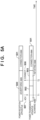
- FIGS. 5A to 5F are diagrams for describing power transmission apparatus and power reception apparatus operation timings
- FIGS. 5A and 5B are diagrams for describing conventional power transmission apparatus and power reception apparatus operation timings.
- description will be provided with reference to the power transmission apparatus 100 and the power reception apparatus 101.
- the power transmission apparatus 100 and the power reception apparatus 101 have already completed procedures F400 to F420 illustrated in FIG. 4 .
- the second communication unit 206 is in a state in which the second communication unit 206 can receive ADV (F421) from the power reception apparatus 101.
- the second communication unit 304 of the power reception apparatus 101 broadcasts ADV 507 at time T1 in an ADVERTISING state 500 in which the second communication unit 304 operates as an Advertiser (F421).
- the second communication unit 206 of the power transmission apparatus 100 can receive ADV 507 in a SCANNING state 502 in which the second communication unit 206 operates as a Scanner.
- the second communication unit 206 of the power transmission apparatus 100 transitions to an INITIATING state 503 for performing BLE connection processing, and transmits CONNECT 508 to the power reception apparatus 101 (F422).
- the second communication unit 206 of the power transmission apparatus 100 transitions to a CONNECTION state 501. Furthermore, upon receiving CONNECT 508 from the power transmission apparatus 100, the second communication unit 304 of the power reception apparatus 101 transitions to the CONNECTION state 501.
- the second communication unit 304 of the power reception apparatus 101 transmits EPT(Re-Ping) 509 defined by the WPC standard to the power transmission apparatus 100 when the second communication unit 206 of the power transmission apparatus 100 and the second communication unit 304 of the power reception apparatus 101 are in the CONNECTION state 501.
- EPT is an abbreviation of End Power Transfer, and is data that is a request to stop power transmission.
- Re-Ping indicates that power transmission is to be stopped for a certain period (Re-Ping time), but D-Ping is to be transmitted again after a predetermined amount of time.
- the power transmission apparatus 100 After receiving EPT(Re-Ping) 509, the power transmission apparatus 100 determines to stop power transmission to the power reception apparatus 101, and stops power transmission within time T_terminate.
- the power transmission apparatus 100 stops power transmission at time T3.
- the second communication unit 304 of the power reception apparatus 101 operates on the power received by the power reception unit 302 rather than power from the battery 307
- the second communication unit 304 terminates the CONNECTION state 501 at time T3, which is the time when the power transmission apparatus 100 stops power transmission.
- the second communication unit 206 of the power reception apparatus 101 does not transmit any data to the power transmission apparatus 100. Because power is reinput to the second communication unit 304 of the power reception apparatus 101 (the second communication unit 304 is turned on again) when communication is resumed, the BD_ADDR thereof may change.
- the second communication unit 206 of the power transmission apparatus 100 includes a timer defined by the BLE standard in order to determine whether or not the BLE connection with the second communication unit 304 of the power reception apparatus 101 is disconnected (link loss).
- the timer is called a Supervision timer, and the timeout time is indicated by "T_sv_to" 506 in the present embodiment. Note that, according to the BLE standard, the timeout time is 20 seconds by default.
- T_sv_to begins at time T3 and times out at time T7.
- the first communication unit 204 re-transmits D-Ping 510 at time T4.
- the power reception apparatus 101 receives D-Ping 510 via the first communication unit 303, and activates the second communication unit 304.
- the second communication unit 304 of the power reception apparatus 101 broadcasts ADV 507 at time T5 in the ADVERTISING state 500 continuing until time T6 (F421).
- the second communication unit 206 of the power transmission apparatus 100 is in the CONNECTION state 501 because the Supervision timer in the power transmission apparatus 100 has not timed out. That is, the second communication unit 206 of the power transmission apparatus 100 cannot receive ADV 507 transmitted at time T5 because the second communication unit 206 is not in the SCANNING state 502. Accordingly, the second communication unit 304 of the power reception apparatus 101 cannot transition to the CONNECTION state 501, and control communication via BLE cannot be performed following this point.
- T_sv_to described above times out at time T7 the second communication unit 206 of the power transmission apparatus 100 can transition to the SCANNING state 502 or the INITIATING state 503. However, this time, the second communication unit 304 of the power reception apparatus 101 has already terminated the ADVERTISING state 500 at time T6. Accordingly, the second communication unit 206 of the power transmission apparatus 100 cannot receive ADV (F421).
- the second communication unit 206 of the power transmission apparatus 100 cannot transition to the SCANNING state or the INITIATING state while the second communication unit 304 of the power reception apparatus 101 is in the ADVERTISING state.
- the power transmission apparatus 100 in the present embodiment operates as follows.
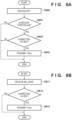
- FIG. 6A shows a flowchart illustrating an example of a flow of processing by the power transmission apparatus 100 in the present embodiment. This flow may be started when the second communication unit 206 of the power transmission apparatus 100 receives EPT from a power reception apparatus while in the CONNECTION state 501, as illustrated in the left side of FIG. 5B .
- step S600 When the second communication unit 206 of the power transmission apparatus 100 receives EPT from a power reception apparatus (step S600), the control unit 201 determines whether or not the reason code included in EPT is Re-Ping (step S601). Processing proceeds to step S602 if the reason code is Re-Ping (Yes in step S601), and processing is terminated if the reason code is not Re-Ping (No in step S601). In step S602, the control unit 201 determines whether or not the second communication unit 206 is connected to a power reception apparatus via BLE. If the second communication unit 206 is connected to a power reception apparatus via BLE (Yes in step S602), the second communication unit 206 transmits TERM to the power reception apparatus (step S603).
- TERM is LL_TERMINATE_IND indicating disconnection of BLE connection.
- the power transmission apparatus 100 stops power transmission after transmitting TERM, and the second communication unit 206 can transition to the SCANNING state 502 or the INITIATING state 503.
- the second communication unit 206 is not connected to any power reception apparatus via BLE (No in step S602), processing is terminated.
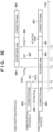
- FIG. 5C is a diagram for describing operation timings of the power reception apparatus 101 and the power transmission apparatus 100 operating based on the flow in FIG. 6A . Furthermore, reference will also be made to the processing from F430 in FIG. 4 .
- the second communication unit 206 of the power transmission apparatus 100 receives EPT(Re-Ping) 509 from the power reception apparatus 101 at time T8 when the second communication unit 206 of the power transmission apparatus 100 and the second communication unit 304 of the power reception apparatus 101 are in the CONNECTION state 501 (F430). Because the second communication unit 206 is connected to the second communication unit 304 of the power reception apparatus 101 via BLE, the second communication unit 206 transmits TERM 511 at time T9 (F431). Subsequently, the power transmission apparatus 100 stops power transmission. Then, at time T10 after the elapse of the Re-Ping time, the first communication unit 204 of the power transmission apparatus 100 re-transmits D-Ping 510 (F432).
- the power reception apparatus 101 receives D-Ping 510 via the first communication unit 303, and activates the second communication unit 206. After procedures F403 to F420 (F433) in FIG. 4 , the second communication unit 304 of the power reception apparatus 101 broadcasts ADV 507 at time T11 (F434).
- the second communication unit 206 of the power transmission apparatus 100 has transmitted TERM at time T9, the second communication unit 206 is in the SCANNING state 502 or the INITIATING state 503 after time T9. That is, after time T9, the second communication unit 206 of the power transmission apparatus 100 is in the SCANNING state 502, which means that the second communication unit 206 transitions to a state in which ADV, which is information necessary for the connection with the second communication unit 304 of the power reception apparatus 101, can be received. Then, after receiving ADV transmitted from the second communication unit 304 of the power reception apparatus 101 at time T 11, the second communication unit 206 of the power transmission apparatus 100 transmits CONNECT 508 at time T12 in the INITIATING state 503 (F435).
- the power transmission apparatus 100 in the present embodiment can re-establish BLE connection with a power reception apparatus using the second communication unit 206 upon resuming power transmission after stopping power transmission.
- a configuration is adopted such that, upon receiving EPT(Re-Ping) 509, the second communication unit 206 of the power transmission apparatus 100 transmits TERM 511 before power transmission is stopped.
- the second communication unit 206 may transmit TERM after power transmission is stopped.
- a configuration may be adopted such that the second communication unit 206 transmits TERM after the power transmission apparatus 100 stops power transmission at time T9 and before the first communication unit 204 starts to re-transmit D-Ping at time T10.
- the second communication unit 206 may transmit TERM after the first communication unit 204 starts to re-transmit D-Ping again at time T10 and before ADV is received at time T11.
- FIG. 6B shows a flowchart illustrating another example of a flow of processing by the power transmission apparatus 100 in the present embodiment. This flow may be started when the second communication unit 206 of the power transmission apparatus 100 is in the CONNECTION state 501, as illustrated in the left side of FIG. 5B .
- step S612 When the first communication unit 204 of the power transmission apparatus 100 receives BD_ADDR from a power reception apparatus via in-band communication (step S611), processing proceeds to step S612.
- step S612 the control unit 201 determines whether or not the second communication unit 206 is connected to a power reception apparatus via BLE. If the second communication unit 206 is connected to a power reception apparatus via BLE (Yes in step S602), the control unit 201 determines to stop power transmission to the power reception apparatus. Then, the second communication unit 206 transmits TERM to the power reception apparatus (S613).
- the second communication unit 206 may transmit TERM before transmitting CONNECT 508 to BD_ADDR received via in-band communication at time T12.
- the second communication unit 206 is not connected to any power reception apparatus via BLE (No in step S612), processing is terminated.
- the power reception apparatus can transmit BD_ADDR to the power transmission apparatus via in-band communication, and the power transmission apparatus and the power reception apparatus can re-attempt to establish connection via BLE.
- the second communication unit 206 of the power transmission apparatus 100 transmits TERM.
- the second communication unit 304 of the power reception apparatus 101 may transmit TERM at the same timing as a timing described above. For example, if the control unit 301 of the power reception apparatus 101, due to some reason, determines to make a request to the power transmission apparatus 100 so that power reception stops, the second communication unit 304 may transmit TERM to the power transmission apparatus 100.
- the power transmission apparatus 100 may set the timeout time (T_sv_to) of the Supervision timer, which is for determining whether BLE connection with the power reception apparatus 101 is disconnected (link loss), in accordance with the Re-Ping time. For example, the power transmission apparatus 100 may set T_sv_to so as to be shorter than the Re-Ping time.
- FIG. 5D is a diagram for describing operation timings of the power reception apparatus 101 and the power transmission apparatus 100 operating in such a manner.
- the second communication unit 206 of the power transmission apparatus 100 receives EPT(Re-ping) 509 from the power reception apparatus 101 when the second communication unit 206 of the power transmission apparatus 100 and the second communication unit 304 of the power reception apparatus 101 are in the CONNECTION state 501. Subsequently, the power transmission apparatus 100 stops power transmission at time T13. Then, at time T15 after the elapse of the Re-Ping time (T_reping 505 in the drawing), the first communication unit 204 of the power transmission apparatus 100 re-transmits D-Ping 510.
- T_reping 505 the Re-Ping time
- the power transmission apparatus 100 sets T_sv_to 506 to a shorter time than T_reping 505. This being the case, the Supervision timer times out at time T14, and the second communication unit 206 of the power transmission apparatus 100 transitions to the SCANNING state or the INITIATING state and can receive ADV and transmit CONNECT.
- the power transmission apparatus 100 functioning as a BLE central determines a value that is in accordance with the Re-Ping time as the timeout time (T_sv_to) of the Supervision timer, and sets the value as the timeout time (T_sv_to) of the Supervision timer.
- the power reception apparatus 101 functioning as a BLE peripheral may determine a value that is in accordance with the Re-Ping time as the timeout time (T_sv_to) and request the power transmission apparatus 100 to set the value as the timeout time (T_sv_to).
- This request can be made by transmitting, to the power transmission apparatus 100, a BLE packet including the command L2CAP_CONNECTION_PARAMETER_UPDATE _REQ or LL_CONNECTION PARAM REQ according to the BLE standard.
- the power reception apparatus 101 transmits the BLE packet at a timing included in the period of the CONNECTION state 501 in FIG. 5D .
- the power transmission apparatus 100 sets the timeout time (T_sv_to) included in the BLE packet.
- the control unit 201 of the power transmission apparatus 100 uses an operating system (OS), which is a basic software, in order to perform BLE communication. Due to constraints of this OS, there are cases in which the power transmission apparatus 100 cannot set the timeout time of the Supervision timer to a value desired by the power transmission apparatus 100. In such cases, by adopting the above-described configuration, the timeout time (T_sv_to) of the Supervision timer can be set to a value that is in accordance with the Re-Ping time. In such a manner, one of the power transmission apparatus 100 and the power reception apparatus 101 determines the timeout time and sets the timeout time to the other by transmitting a signal in which the timeout time can be specified. Thus, the timeout time can be set in accordance with the Re-Ping time even if one of the devices cannot determine the timeout time due to OS constraints.
- OS operating system
- the power transmission apparatus 100 determines to stop/suspend power transmission upon receiving EPT (EPT(Re-Ping)) including the reason code Re-Ping has been described.
- EPT EPT(Re-Ping)
- the power transmission apparatus 100 may suspend power transmission upon receiving data including another reason code for suspending power transmission.
- the power transmission apparatus 100 may determine to stop/suspend power transmission if the control unit 201 detects a foreign object based on power transmitted as a result of control by the control unit 201.
- the power transmission apparatus 100 has the function of maintaining the SCANNING state and establishing BLE connection with a power reception apparatus 101 by receiving ADV from the power reception apparatus 101 even during a period in which the power transmission apparatus 100 is in the CONNECTION state or INITIATING state with another power reception apparatus 101.
- step S603 the condition in step S602 is that BLE connection is established with one power reception apparatus.
- the condition that BLE connection is established with N (N ⁇ 2) or more power reception apparatuses may be adopted as the condition in step S602.
- the destination to which TERM is transmitted in step S603 is the power reception apparatus from which the EPT received via in-band communication in step S600 was transmitted.
- the power transmission apparatus 100 can continue using BLE connection with the power reception apparatus 101 via an application other than out-band communication for controlling power transmission. Furthermore, even in such a case, the power reception apparatus 101 can transmit power to and establish BLE connection with a predetermined number or more power reception apparatuses other than the power reception apparatus 101.
- the power transmission apparatus 100 operates as a BLE central, and the power reception apparatus 101 operates as a BLE peripheral.
- the power transmission apparatus 100 may operate as a peripheral, and the power reception apparatus 101 may operate as a central.
- the power transmission apparatus 100 transmits power to and establishes BLE connection with one power reception apparatus 101 (hereinafter power reception apparatus A), and then transmits power to and establishes BLE connection with another power reception apparatus 101 (hereinafter power reception apparatus B).
- power reception apparatus A one power reception apparatus 101
- power reception apparatus B another power reception apparatus 101
- this situation may occur when the power reception apparatus A is removed by a user and replaced with the power reception apparatus B.
- FIG. 5E is a diagram describing operation timings of the power transmission apparatus and the power reception apparatuses A and B in the present embodiment.
- the second communication unit 206 of the power transmission apparatus 100 receives EPT(Re-Ping) 509 from the power reception apparatus A at time T8 when the second communication unit 206 of the power transmission apparatus 100 and the second communication unit 304 of the power reception apparatus A are in the CONNECTION state 501.
- the second communication unit 206 transmits TERM 511 at time T9 because the second communication unit 206 is connected to the second communication unit 304 of the power reception apparatus A via BLE.
- the power transmission apparatus 100 stops power transmission.
- the power reception apparatus A is removed by a user and replaced with the power reception apparatus B between time T9 and time T10.
- the first communication unit 204 of the power transmission apparatus 100 re-transmits D-Ping 510.
- the power reception apparatus B receives D-Ping 510 via the first communication unit 303, and activates the second communication unit 206.
- the second communication unit 304 of the power reception apparatus B broadcasts ADV 507 at time T11.
- the second communication unit 206 of the power transmission apparatus 100 has transmitted TERM at time T9, the second communication unit 206 is in the SCANNING state 502 or the INITIATING state 503 after time T9. That is, after time T9, the second communication unit 206 of the power transmission apparatus 100 is in the SCANNING state 502, which means that the second communication unit 206 transitions to a state in which ADV, which is information necessary for the connection with the second communication unit 304 of the power reception apparatus B, can be received. Then, at time T11, the second communication unit 206 of the power transmission apparatus 100 receives ADV transmitted from the second communication unit 304 of the power reception apparatus B.
- the ADV is that from the power reception apparatus B based on whether or not BD_ADDR included in the ADV matches the BD_ADDR received via in-band communication in F413. If the BD_ADDRs match, the power transmission apparatus 100 transmits CONNECT 508 at time T12 in the INITIATING state 503.
- the power transmission apparatus 100 in the present embodiment can establish BLE connection with the power reception apparatus B in a case in which the power transmission apparatus 100 starts power transmission to the power reception apparatus B after stopping power transmission to the power reception apparatus A.
- the power transmission apparatus 100 upon receiving EPT (EPT(Re-Ping) 509) including the reason code Re-Ping, transmits TERM 511 before stopping power transmission.
- the power transmission apparatus 100 may perform the same processing upon receiving EPT including a reason code indicating the completion of charging.
- the power transmission apparatus 100 can transmit power to and establish BLE connection with the power reception apparatus B also in a case in which the user replaces the power reception apparatus A with the power reception apparatus B upon completion of charging of the power reception apparatus A.
- the power transmission apparatus 100 transmits D-Ping 510 at time T10.
- a configuration may be adopted such that the power transmission apparatus 100 repeatedly transmits A-Ping starting from time T10, and transmits D-Ping 510 after an object is detected.
- the power transmission apparatus 100 can transmit power to and establish BLE connection with the power reception apparatus B even if there is an interval until the power reception apparatus B is mounted after the power reception apparatus A is removed.
- a configuration may be adopted such that the above-described processing is performed in a case in which EPT including a reason code other than the reason code Re-Ping, e.g., a reason code indicating the completion of charging, is received.
- the power transmission apparatus 100 upon receiving EPT(Re-Ping) 509, transmits TERM 511 before stopping power transmission.
- the power transmission apparatus 100 may perform the same processing if CE or RP0 to be constantly received from the power reception apparatus A cannot be received continuously for a predetermined amount of time or more.
- the predetermined amount of time is an amount of time exceeding a transmission interval, as defined by the WPC standard, at which the power reception apparatus 101 transmits CE or RP0.
- the power transmission apparatus 100 can transmit power to and establish BLE connection with the power reception apparatus B even if the power reception apparatus A is removed and replaced with the power reception apparatus B while power is being transmitted to the power reception apparatus A in the Power Transfer phase.
- the power transmission apparatus 100 in the present embodiment may set the timeout time (T_sv_to) of the Supervision timer, which is for determining whether BLE connection with the power reception apparatus 101 is disconnected (link loss), in accordance with the Re-Ping time.
- FIG. 5F is a diagram for describing operation timings of the power reception apparatuses A and B and the power transmission apparatus 100 operating in such a manner.
- the second communication unit 206 of the power transmission apparatus 100 receives EPT(Re-Ping) 509 from the power reception apparatus A when the second communication unit 206 of the power transmission apparatus 100 and the second communication unit 304 of the power reception apparatus A are in the CONNECTION state 501. Subsequently, the power transmission apparatus 100 stops power transmission at time T13.
- the power reception apparatus A is removed by a user and replaced with the power reception apparatus B between time T13 and time T15.
- the first communication unit 204 of the power transmission apparatus 100 re-transmits D-Ping 510.
- the power reception apparatus B receives D-Ping 510 via the first communication unit 303, and activates the second communication unit 206.
- the second communication unit 304 of the power reception apparatus B broadcasts ADV 507 at time T11.
- the power transmission apparatus 100 sets T_sv_to 506 to a shorter time than T_reping 505.
- the Supervision timer times out at time T14, and the second communication unit 206 of the power transmission apparatus 100 transitions to the SCANNING state or the INITIATING state and can receive ADV transmitted by the power reception apparatus B and transmit CONNECT.
- the above-described processing illustrated in FIGS. 6A and 6B may be realized by the control unit 201 of the power transmission apparatus 100 controlling functional units by reading and executing programs stored in advance.
- the control unit 201 of the power transmission apparatus 100 controlling functional units by reading and executing programs stored in advance.
- at least part of such processing may be realized using hardware.
- a dedicated circuit may be automatically generated on a field-programmable gate array (FPGA) from a program for realizing each processing step using a predetermined compiler.
- FPGA field-programmable gate array
- a configuration may be adopted such that hardware executing at least part of the above-described processing is realized by forming a gate array circuit in a manner similar to that when an FPGA is used.
- the present invention can also be realized by processing in which a program realizing one or more of the functions in the above-described embodiments is supplied to a system or device via a network or storage medium, and one or more processors of a computer in the system or device read and execute the program. Furthermore, the present invention can also be realized using a circuit (e.g., an ASIC) realizing the one or more functions.
- a circuit e.g., an ASIC
Landscapes
- Engineering & Computer Science (AREA)
- Computer Networks & Wireless Communication (AREA)
- Power Engineering (AREA)
- Signal Processing (AREA)
- Charge And Discharge Circuits For Batteries Or The Like (AREA)
- Near-Field Transmission Systems (AREA)
Applications Claiming Priority (3)
| Application Number | Priority Date | Filing Date | Title |
|---|---|---|---|
| JP2020209553 | 2020-12-17 | ||
| JP2021126879A JP7663451B2 (ja) | 2020-12-17 | 2021-08-02 | 送電装置、受電装置、それらの通信方法、およびプログラム |
| PCT/JP2021/038879 WO2022130778A1 (fr) | 2020-12-17 | 2021-10-21 | Dispositif de transmission d'énergie, dispositif de réception d'énergie, leurs procédés de commande et programme |
Publications (2)
| Publication Number | Publication Date |
|---|---|
| EP4266543A1 true EP4266543A1 (fr) | 2023-10-25 |
| EP4266543A4 EP4266543A4 (fr) | 2024-11-27 |
Family
ID=82059012
Family Applications (1)
| Application Number | Title | Priority Date | Filing Date |
|---|---|---|---|
| EP21906142.1A Withdrawn EP4266543A4 (fr) | 2020-12-17 | 2021-10-21 | Dispositif de transmission d'énergie, dispositif de réception d'énergie, leurs procédés de commande et programme |
Country Status (4)
| Country | Link |
|---|---|
| US (1) | US12176734B2 (fr) |
| EP (1) | EP4266543A4 (fr) |
| KR (1) | KR20230113349A (fr) |
| WO (1) | WO2022130778A1 (fr) |
Families Citing this family (3)
| Publication number | Priority date | Publication date | Assignee | Title |
|---|---|---|---|---|
| JP7621907B2 (ja) * | 2021-07-28 | 2025-01-27 | キヤノン株式会社 | 受電装置、受電装置が行う方法、およびプログラム |
| KR102923623B1 (ko) * | 2021-11-12 | 2026-02-09 | 엘지전자 주식회사 | 무선 전력 전송 시스템에서 아웃 오브 밴드 통신의 연결 방법 및 장치 |
| CN117559668B (zh) * | 2024-01-10 | 2024-03-22 | 成都市易冲半导体有限公司 | 一种功率接收端、无线供电系统及其控制方法 |
Family Cites Families (12)
| Publication number | Priority date | Publication date | Assignee | Title |
|---|---|---|---|---|
| JP5703094B2 (ja) | 2011-03-31 | 2015-04-15 | 株式会社日本総合研究所 | 充電器情報通知システム、及び充電器情報通知方法 |
| CN104584448B (zh) * | 2013-08-07 | 2018-07-17 | 皇家飞利浦有限公司 | 无线感应功率传输 |
| JP6208503B2 (ja) | 2013-09-11 | 2017-10-04 | ローム株式会社 | ワイヤレス受電装置、その制御回路および制御方法 |
| JP2015180177A (ja) * | 2014-02-25 | 2015-10-08 | 船井電機株式会社 | 給電装置および給電方法 |
| JP6494227B2 (ja) * | 2014-09-22 | 2019-04-03 | キヤノン株式会社 | 給電装置、制御方法およびプログラム |
| KR102607753B1 (ko) * | 2016-11-15 | 2023-11-29 | 엘지전자 주식회사 | 무선 전력 전달 방법 및 이를 위한 장치 |
| US10804726B2 (en) * | 2017-01-15 | 2020-10-13 | Chargedge, Inc. | Wheel coils and center-tapped longitudinal coils for wireless power transfer |
| JP7037276B2 (ja) | 2017-02-08 | 2022-03-16 | キヤノン株式会社 | 受電装置、送電装置、方法、及びプログラム |
| JP7117884B2 (ja) * | 2018-04-09 | 2022-08-15 | キヤノン株式会社 | 受電装置、送電装置、制御方法、及びプログラム |
| JP7100572B2 (ja) * | 2018-12-14 | 2022-07-13 | キヤノン株式会社 | 受電装置、受電装置の制御方法及びプログラム |
| JP7278855B2 (ja) * | 2019-04-24 | 2023-05-22 | キヤノン株式会社 | 送電装置、送電装置が実行する制御方法、及びプログラム |
| JP7424094B2 (ja) | 2020-02-17 | 2024-01-30 | ブラザー工業株式会社 | 液体吐出装置、その制御方法及びプログラム |
-
2021
- 2021-10-21 EP EP21906142.1A patent/EP4266543A4/fr not_active Withdrawn
- 2021-10-21 KR KR1020237021283A patent/KR20230113349A/ko active Pending
- 2021-10-21 WO PCT/JP2021/038879 patent/WO2022130778A1/fr not_active Ceased
-
2023
- 2023-06-14 US US18/334,998 patent/US12176734B2/en active Active
Also Published As
| Publication number | Publication date |
|---|---|
| KR20230113349A (ko) | 2023-07-28 |
| WO2022130778A1 (fr) | 2022-06-23 |
| US20230327500A1 (en) | 2023-10-12 |
| US12176734B2 (en) | 2024-12-24 |
| EP4266543A4 (fr) | 2024-11-27 |
Similar Documents
| Publication | Publication Date | Title |
|---|---|---|
| US11937315B2 (en) | Power receiving apparatus, power transmission apparatus, control method, and non-transitory computer-readable storage medium | |
| US12176734B2 (en) | Power transmission apparatus, power reception apparatus, communication methods therefor, and non-transitory computer-readable storage medium | |
| JP7809858B2 (ja) | 送電装置、及び方法 | |
| US11876872B2 (en) | Method, device and computer program for communicating information relating to wireless power transmission, and recording medium thereof | |
| JP6590497B2 (ja) | 送電装置、送電装置が行う制御方法、受電装置、受電装置が行う制御方法、及びプログラム | |
| KR102079843B1 (ko) | 송전 장치, 송전 장치의 제어 방법, 및 저장 매체 | |
| JP6516519B2 (ja) | 送電装置、送電装置が行う制御方法、及びプログラム | |
| US12456885B2 (en) | Power transmitting apparatus, control method for power transmitting apparatus, and storage medium | |
| US20250226703A1 (en) | Power receiving apparatus, power transmitting apparatus, control methods thereof, and non-transitory computer-readable storage medium | |
| US20240195231A1 (en) | Power transmitting apparatus, power receiving apparatus, method, and storage medium | |
| JP7663451B2 (ja) | 送電装置、受電装置、それらの通信方法、およびプログラム | |
| JP7735099B2 (ja) | 電子機器、電子機器の制御方法およびプログラム | |
| JP7753021B2 (ja) | 送電装置、受電装置、制御方法及びプログラム | |
| US12034316B2 (en) | Power transmitting apparatus, control method for power transmitting apparatus, and storage medium | |
| WO2022230714A1 (fr) | Appareil électronique et procédé de commande d'appareil électronique | |
| JP2022096591A5 (ja) | 送電装置、受電装置、それらの通信方法、およびプログラム |
Legal Events
| Date | Code | Title | Description |
|---|---|---|---|
| STAA | Information on the status of an ep patent application or granted ep patent |
Free format text: STATUS: THE INTERNATIONAL PUBLICATION HAS BEEN MADE |
|
| PUAI | Public reference made under article 153(3) epc to a published international application that has entered the european phase |
Free format text: ORIGINAL CODE: 0009012 |
|
| STAA | Information on the status of an ep patent application or granted ep patent |
Free format text: STATUS: REQUEST FOR EXAMINATION WAS MADE |
|
| 17P | Request for examination filed |
Effective date: 20230717 |
|
| AK | Designated contracting states |
Kind code of ref document: A1 Designated state(s): AL AT BE BG CH CY CZ DE DK EE ES FI FR GB GR HR HU IE IS IT LI LT LU LV MC MK MT NL NO PL PT RO RS SE SI SK SM TR |
|
| DAV | Request for validation of the european patent (deleted) | ||
| DAX | Request for extension of the european patent (deleted) | ||
| A4 | Supplementary search report drawn up and despatched |
Effective date: 20241029 |
|
| RIC1 | Information provided on ipc code assigned before grant |
Ipc: H04B 5/79 20240101ALI20241023BHEP Ipc: H04B 5/26 20240101ALI20241023BHEP Ipc: H02J 7/00 20060101ALI20241023BHEP Ipc: H02J 50/80 20160101ALI20241023BHEP Ipc: H02J 50/60 20160101ALI20241023BHEP Ipc: H02J 50/40 20160101ALI20241023BHEP Ipc: H02J 50/12 20160101ALI20241023BHEP Ipc: H02J 50/10 20160101AFI20241023BHEP |
|
| STAA | Information on the status of an ep patent application or granted ep patent |
Free format text: STATUS: THE APPLICATION HAS BEEN WITHDRAWN |
|
| 18W | Application withdrawn |
Effective date: 20250417 |