EP4267895B1 - Kryogenes kühlsystem und kryogene pumpe - Google Patents
Kryogenes kühlsystem und kryogene pumpe Download PDFInfo
- Publication number
- EP4267895B1 EP4267895B1 EP21843980.0A EP21843980A EP4267895B1 EP 4267895 B1 EP4267895 B1 EP 4267895B1 EP 21843980 A EP21843980 A EP 21843980A EP 4267895 B1 EP4267895 B1 EP 4267895B1
- Authority
- EP
- European Patent Office
- Prior art keywords
- refrigerant
- compressor
- refrigeration system
- pressure
- variable speed
- Prior art date
- Legal status (The legal status is an assumption and is not a legal conclusion. Google has not performed a legal analysis and makes no representation as to the accuracy of the status listed.)
- Active
Links
Images

Classifications
-
- F—MECHANICAL ENGINEERING; LIGHTING; HEATING; WEAPONS; BLASTING
- F04—POSITIVE - DISPLACEMENT MACHINES FOR LIQUIDS; PUMPS FOR LIQUIDS OR ELASTIC FLUIDS
- F04B—POSITIVE-DISPLACEMENT MACHINES FOR LIQUIDS; PUMPS
- F04B37/00—Pumps having pertinent characteristics not provided for in, or of interest apart from, groups F04B25/00 - F04B35/00
- F04B37/06—Pumps having pertinent characteristics not provided for in, or of interest apart from, groups F04B25/00 - F04B35/00 for evacuating by thermal means
- F04B37/08—Pumps having pertinent characteristics not provided for in, or of interest apart from, groups F04B25/00 - F04B35/00 for evacuating by thermal means by condensing or freezing, e.g. cryogenic pumps
-
- F—MECHANICAL ENGINEERING; LIGHTING; HEATING; WEAPONS; BLASTING
- F25—REFRIGERATION OR COOLING; COMBINED HEATING AND REFRIGERATION SYSTEMS; HEAT PUMP SYSTEMS; MANUFACTURE OR STORAGE OF ICE; LIQUEFACTION SOLIDIFICATION OF GASES
- F25B—REFRIGERATION MACHINES, PLANTS OR SYSTEMS; COMBINED HEATING AND REFRIGERATION SYSTEMS; HEAT PUMP SYSTEMS
- F25B41/00—Fluid-circulation arrangements
- F25B41/20—Disposition of valves, e.g. of on-off valves or flow control valves
-
- F—MECHANICAL ENGINEERING; LIGHTING; HEATING; WEAPONS; BLASTING
- F25—REFRIGERATION OR COOLING; COMBINED HEATING AND REFRIGERATION SYSTEMS; HEAT PUMP SYSTEMS; MANUFACTURE OR STORAGE OF ICE; LIQUEFACTION SOLIDIFICATION OF GASES
- F25B—REFRIGERATION MACHINES, PLANTS OR SYSTEMS; COMBINED HEATING AND REFRIGERATION SYSTEMS; HEAT PUMP SYSTEMS
- F25B49/00—Arrangement or mounting of control or safety devices
- F25B49/02—Arrangement or mounting of control or safety devices for compression type machines, plants or systems
- F25B49/025—Motor control arrangements
-
- F—MECHANICAL ENGINEERING; LIGHTING; HEATING; WEAPONS; BLASTING
- F25—REFRIGERATION OR COOLING; COMBINED HEATING AND REFRIGERATION SYSTEMS; HEAT PUMP SYSTEMS; MANUFACTURE OR STORAGE OF ICE; LIQUEFACTION SOLIDIFICATION OF GASES
- F25B—REFRIGERATION MACHINES, PLANTS OR SYSTEMS; COMBINED HEATING AND REFRIGERATION SYSTEMS; HEAT PUMP SYSTEMS
- F25B9/00—Compression machines, plants or systems, in which the refrigerant is air or other gas of low boiling point
- F25B9/002—Compression machines, plants or systems, in which the refrigerant is air or other gas of low boiling point characterised by the refrigerant
-
- F—MECHANICAL ENGINEERING; LIGHTING; HEATING; WEAPONS; BLASTING
- F25—REFRIGERATION OR COOLING; COMBINED HEATING AND REFRIGERATION SYSTEMS; HEAT PUMP SYSTEMS; MANUFACTURE OR STORAGE OF ICE; LIQUEFACTION SOLIDIFICATION OF GASES
- F25B—REFRIGERATION MACHINES, PLANTS OR SYSTEMS; COMBINED HEATING AND REFRIGERATION SYSTEMS; HEAT PUMP SYSTEMS
- F25B9/00—Compression machines, plants or systems, in which the refrigerant is air or other gas of low boiling point
- F25B9/14—Compression machines, plants or systems, in which the refrigerant is air or other gas of low boiling point characterised by the cycle used, e.g. Stirling cycle
-
- F—MECHANICAL ENGINEERING; LIGHTING; HEATING; WEAPONS; BLASTING
- F25—REFRIGERATION OR COOLING; COMBINED HEATING AND REFRIGERATION SYSTEMS; HEAT PUMP SYSTEMS; MANUFACTURE OR STORAGE OF ICE; LIQUEFACTION SOLIDIFICATION OF GASES
- F25B—REFRIGERATION MACHINES, PLANTS OR SYSTEMS; COMBINED HEATING AND REFRIGERATION SYSTEMS; HEAT PUMP SYSTEMS
- F25B2500/00—Problems to be solved
- F25B2500/26—Problems to be solved characterised by the startup of the refrigeration cycle
-
- F—MECHANICAL ENGINEERING; LIGHTING; HEATING; WEAPONS; BLASTING
- F25—REFRIGERATION OR COOLING; COMBINED HEATING AND REFRIGERATION SYSTEMS; HEAT PUMP SYSTEMS; MANUFACTURE OR STORAGE OF ICE; LIQUEFACTION SOLIDIFICATION OF GASES
- F25B—REFRIGERATION MACHINES, PLANTS OR SYSTEMS; COMBINED HEATING AND REFRIGERATION SYSTEMS; HEAT PUMP SYSTEMS
- F25B2600/00—Control issues
- F25B2600/02—Compressor control
- F25B2600/024—Compressor control by controlling the electric parameters, e.g. current or voltage
-
- F—MECHANICAL ENGINEERING; LIGHTING; HEATING; WEAPONS; BLASTING
- F25—REFRIGERATION OR COOLING; COMBINED HEATING AND REFRIGERATION SYSTEMS; HEAT PUMP SYSTEMS; MANUFACTURE OR STORAGE OF ICE; LIQUEFACTION SOLIDIFICATION OF GASES
- F25B—REFRIGERATION MACHINES, PLANTS OR SYSTEMS; COMBINED HEATING AND REFRIGERATION SYSTEMS; HEAT PUMP SYSTEMS
- F25B2600/00—Control issues
- F25B2600/02—Compressor control
- F25B2600/025—Compressor control by controlling speed
- F25B2600/0253—Compressor control by controlling speed with variable speed
-
- F—MECHANICAL ENGINEERING; LIGHTING; HEATING; WEAPONS; BLASTING
- F25—REFRIGERATION OR COOLING; COMBINED HEATING AND REFRIGERATION SYSTEMS; HEAT PUMP SYSTEMS; MANUFACTURE OR STORAGE OF ICE; LIQUEFACTION SOLIDIFICATION OF GASES
- F25B—REFRIGERATION MACHINES, PLANTS OR SYSTEMS; COMBINED HEATING AND REFRIGERATION SYSTEMS; HEAT PUMP SYSTEMS
- F25B2600/00—Control issues
- F25B2600/02—Compressor control
- F25B2600/027—Compressor control by controlling pressure
- F25B2600/0271—Compressor control by controlling pressure the discharge pressure
-
- F—MECHANICAL ENGINEERING; LIGHTING; HEATING; WEAPONS; BLASTING
- F25—REFRIGERATION OR COOLING; COMBINED HEATING AND REFRIGERATION SYSTEMS; HEAT PUMP SYSTEMS; MANUFACTURE OR STORAGE OF ICE; LIQUEFACTION SOLIDIFICATION OF GASES
- F25B—REFRIGERATION MACHINES, PLANTS OR SYSTEMS; COMBINED HEATING AND REFRIGERATION SYSTEMS; HEAT PUMP SYSTEMS
- F25B2600/00—Control issues
- F25B2600/02—Compressor control
- F25B2600/027—Compressor control by controlling pressure
- F25B2600/0272—Compressor control by controlling pressure the suction pressure
-
- F—MECHANICAL ENGINEERING; LIGHTING; HEATING; WEAPONS; BLASTING
- F25—REFRIGERATION OR COOLING; COMBINED HEATING AND REFRIGERATION SYSTEMS; HEAT PUMP SYSTEMS; MANUFACTURE OR STORAGE OF ICE; LIQUEFACTION SOLIDIFICATION OF GASES
- F25B—REFRIGERATION MACHINES, PLANTS OR SYSTEMS; COMBINED HEATING AND REFRIGERATION SYSTEMS; HEAT PUMP SYSTEMS
- F25B2700/00—Sensing or detecting of parameters; Sensors therefor
- F25B2700/15—Power, e.g. by voltage or current
- F25B2700/151—Power, e.g. by voltage or current of the compressor motor
-
- Y—GENERAL TAGGING OF NEW TECHNOLOGICAL DEVELOPMENTS; GENERAL TAGGING OF CROSS-SECTIONAL TECHNOLOGIES SPANNING OVER SEVERAL SECTIONS OF THE IPC; TECHNICAL SUBJECTS COVERED BY FORMER USPC CROSS-REFERENCE ART COLLECTIONS [XRACs] AND DIGESTS
- Y02—TECHNOLOGIES OR APPLICATIONS FOR MITIGATION OR ADAPTATION AGAINST CLIMATE CHANGE
- Y02B—CLIMATE CHANGE MITIGATION TECHNOLOGIES RELATED TO BUILDINGS, e.g. HOUSING, HOUSE APPLIANCES OR RELATED END-USER APPLICATIONS
- Y02B30/00—Energy efficient heating, ventilation or air conditioning [HVAC]
- Y02B30/70—Efficient control or regulation technologies, e.g. for control of refrigerant flow, motor or heating
Definitions
- the field of the invention relates to cryogenic refrigeration systems, cryogenic pumps and methods of refrigerating.
- Cryogenic refrigeration systems are known. Such systems use a refrigeration process such as the Gifford-McMahon process and generally comprise an expansion type refrigerator unit housing a thermal accumulation material and an expansion chamber. A compressor compresses a refrigerant gas and supplies the compressed refrigerant to the refrigerator unit where it is cooled by the thermal accumulation material and then expanded. The reduced pressure refrigerant gas is returned to the compressor, thereby forming a refrigerating cycle. An extremely low temperature may be obtained by repeating this refrigerating cycle. For low cryogenic refrigeration helium may be the preferred refrigerant.
- KR 102 033 991 B1 discloses a power saving device for a helium compressor in a cryo-pump system.
- the control arrangement for the operation of the helium compressor and the cryo-pump supplies power from the compressor power supply to the compressor and from the pump control module to the cryo-pump.
- the cryo-pump consumes the maximum driving current to cool the target object, while the compressor is controlled to operate at a high frequency pattern.
- a first aspect provides a cryogenic refrigeration system as defined in claim 1. It comprises: a refrigerator unit comprising an expansion unit; a variable speed compressor configured to compress refrigerant, said variable speed compressor being configured to receive refrigerant from said refrigerator unit via a lower pressure line and to supply compressed refrigerant to said refrigerator unit via a higher pressure line; and control circuitry configured to control said variable speed compressor to maintain a power consumption of said variable speed compressor below a predetermined threshold value, by during cooldown controlling said compressor to initially operate at a reduced frequency and later increasing a frequency of operation of said variable speed compressor such that said variable speed compressor operates at a higher frequency.
- the effectiveness of a refrigeration process is increased with an increased pressure difference between the higher pressure and lower pressure lines and with an increased mass flow rate of refrigerant. Increases in these factors can be achieved by increasing the filling pressure of the system as well as by increasing the compressor speed. However, increasing the compressor speed and increasing the pressure of the refrigerant both increase the power consumption of the compressor and the power consumption of a compressor is generally limited to avoid it overheating and failing.
- the inventors of the present invention recognised that the power consumption of the compressor varies during operation and in particular, may be at its highest during cooldown and be lower during steady state operation. In particular, as the temperature decreases there may be some accumulation of the refrigerant in the refrigeration unit and the pressure of the refrigerant will fall. This fall in pressure allows the compressor to operate at a higher frequency without requiring additional power.
- control circuitry to be provided to control the compressor to operate at a lower speed initially during cooldown and thereby limit the power supplied to the compressor, then the frequency of operation could be increased later as the pressure of refrigerant falls. This would allow the compressor to be configured to operate at higher frequencies during steady state operation while being protected from overheating during cooldown and an improved performance could be provided.
- said cryogenic refrigeration system is provided with additional refrigerant by at least one of: increasing an initial filling pressure such that operation of said variable speed compressor at full speed during cool down of said refrigerator unit would result in the variable speed compressor consuming power above said predetermined threshold value; or by providing a buffer volume of refrigerant in fluid communication with a low pressure line supplying lower pressure refrigerant from said refrigeration unit to said compressor.
- the refrigeration or cooling power of a refrigeration process such as the Gifford-McMahon process is driven by the pressure difference of the working fluid or refrigerant.
- supply pressure high pressure level
- return pressure lower pressure level
- the cooling power of the system is higher the higher the pressure difference between these two pressures.
- the higher the mass flow rate of refrigerant through the system the higher the cooling power provided.
- This pressure increase provided by the compressor should therefore be as high as possible.
- the capacity of the compressor is limited by its compression ratio and the maximum allowed power consumption, which in many cases is related to the maximum allowed current in the motor windings of the motor driving the compressor.
- the compression ratio depends firstly on the volume ratio between the high and low pressure volume of the system and secondly from the filling pressure of the system and thirdly of course from the equilibrium between refrigerant demand of the refrigeration unit and the pump capacity of the compressor.
- Improved cooling power of the refrigeration unit may be provided by increasing the filling pressure of the refrigerant.
- increasing the filling pressure both the high and low pressures will increase and therefore the recirculated mass flow of the refrigerant rises. However, this will increase the demand for electrical power needed for the compression of the refrigerant as well.
- Providing control circuitry to control the speed of operation of the compressor and to limit the power consumed allows the system to be designed with additional refrigerant.
- an additional amount of refrigerant may be provided by increasing the initial filling pressure, in effect over filling the refrigeration system and/or by providing an additional buffer volume in fluid communication with the lower pressure line and thereby changing the volume ratio between the high and low pressure volumes.
- the initial filling pressure of a system is generally set so that when the compressor operates at full speed it will not consume power above its specified power consumption value and will therefore not overheat or cut out. Having a control system that sets the maximum power that can be consumed by the compressor allows the initial filling pressure of the refrigerant to be increased without the risk of the compressor overheating and cutting out. In some cases however the compressor may not operate effectively at a high pressure and in this case, the additional refrigerant may be supplied in the form of an additional buffer volume and thereby additional refrigerant is present without increasing the initial filling pressure.
- the additional filling pressure is the pressure of the refrigerant in the system when the system is not operational.
- This initial filling pressure may be specified for a particular refrigeration system.
- the full speed of operation of the compressor may be the maximum operational speed or frequency of the compressor in the steady cooled stage of operation where the low temperature is maintained and the refrigeration system is not in power save mode.
- control circuitry is further configured to control said variable speed compressor to maintain the pressure of said higher and lower pressure lines within predetermined limit values.
- Compressors may operate effectively within certain pressure limits
- scroll compressors for example may have a performance map which defines limit values of high and low pressure, operation within these limits being acceptable. These limits are dependent upon the mechanics of the pump, namely the housing strength and upon thermodynamic (thermal balance) limitations of the scroll unit.
- control circuitry that is configured to control the speed of the compressor in order to limit the power consumption can also be used to control the speed to maintain the operation of the compressor within these predefined pressure limits.
- said refrigeration system further comprises at least one pressure sensor to sense the pressure difference between the higher and lower pressure lines.
- the system may comprise a higher pressure line sensor and a lower pressure line sensor or it may comprise a differential pressure sensor for measuring the difference in pressure between the two pressure lines. Signals from these pressure sensors are sent to the control circuitry.
- the cryogenic refrigeration system further comprises an inlet valve on said higher pressure line; and said control circuitry is further configured to control said inlet valve to maintain the pressure of said higher and lower pressure lines within predetermined limit values.
- control circuitry is configured to maintain a pressure differential between said higher pressure line and said lower pressure line within predetermined limit values.
- control circuitry may control both the speed of the compressor and the operation of the inlet valve in order to keep the higher and lower pressure values within predetermined limits.
- control circuitry may also control an inlet valve to the refrigeration unit so as to maintain a desired pressure difference between the higher pressure and lower pressure lines and ensure an effective cooling.
- said control circuitry is configured to increase said frequency of operation of said variable speed compressor in response to a detected fall in power consumption of said variable speed compressor.
- said maximum frequency of operation during steady state operation is between 50 and 70 Hz and said initial frequency of operation during cooldown is lower between 30 and 50Hz.
- the initial frequency of operation may be substantially less than the steady state frequency of operation, in some cases it may be 35hz increasing until it reaches the maximum frequency of operation which in some embodiments is 60hz. This is a frequency of operation which the variable speed compressor operates at in the steady state. In some embodiments, the steady state operation may be slightly lower than the maximum operating frequency.
- the refrigerant comprises helium.
- said refrigeration unit is configured to cool to 80K, preferably to 50K, more preferably to below 10K, more preferably to 4K.
- the refrigeration unit may be a low temperature refrigeration unit able to cool to 80K, or in some embodiments it may be a particularly low temperature refrigeration unit in some embodiments cooling down as low as 4k.
- the effects of the accumulation of the refrigerant in the refrigeration unit and the corresponding lowering of pressure within the refrigeration system is particularly pronounced where the refrigeration unit operates at the very low temperatures. Thus, embodiments are particularly effective for such refrigeration systems.
- an initial pressure of said refrigerant is 5 %, preferably 10% higher than specified for the refrigeration unit where there is no power control of the variable speed compressor during cooldown.
- said refrigeration system further comprises said buffer volume of refrigerant, said buffer volume containing more than 20% of a total amount of refrigerant within said refrigeration system, preferably more than 50%, in some cases more than 90%.
- the refrigeration system may be provided with additional refrigerant in some cases an additional 20% by volume or mass of refrigerant and in other case more than an additional 50 or 90% of refrigerant.
- the refrigeration system may be configured to operate with a certain amount of refrigerant such that when operating at maximum operational speed of the variable speed compressor from start up the power threshold consumed by the compressor is not exceeded. This is the standard amount of refrigerant for a refrigeration system and embodiments which provide power control of the compressor may provide an additional amount of refrigerant by either increasing the initial filling pressure and/or supplying it in a buffer volume associated with a lower pressure line, the buffer volume altering the volume ratio between the high and low pressure volumes.
- a refrigeration system may be specified to operate with refrigerant at an initial filling pressure of between 13-17 bars. Where it is specified for the lower end of this range then the pressure may be increased by over filing with refrigerant and increasing the filling pressure in the system. This is acceptable with refrigeration systems according to embodiments as the compressor power supply is controlled to be maintained below a threshold value. Where the system is supplied with refrigerant at the higher end of this range then the compressor may not be configured to operate at pressures above that specified and in such a case, additional refrigerant may be supplied using a buffer volume in the low pressure line that alters the volume ratio between the high and low pressure volumes. In some cases, there may be a combination of increasing the pressure of the refrigerant and adding a buffer volume.
- said control circuitry is further configured to control said variable speed compressor in a power save mode to maintain a power consumption of said variable speed compressor below a predetermined reduced threshold value.
- the control circuitry may also be configured to operate a power save mode where in response to determining that there is a reduced load on the refrigeration system during steady state operation it sets a reduced threshold value for the compressor power.
- the same control circuitry as is used for the cool down can then control the power consumption in this reduced load, power save mode.
- a second aspect provides a cryopump comprising a cryogenic refrigeration system according to the first aspect.
- a third aspect provides a method of operating a cryogenic refrigeration system as defined in claim 13. It comprises a refrigerator unit comprising an expansion unit and a variable speed compressor configured to compress a refrigerant, such that a higher pressure refrigerant is supplied to said refrigerator unit and a lower pressure refrigerant is received from said refrigerator unit, said method comprising during an initial cooldown of said refrigeration unit operating said compressor at an initial lower frequency to maintain a power consumed by said variable speed compressor below a predetermined threshold value; and later increasing a frequency of operation of said compressor to a full speed of operation.
- the method further comprises an initial step of providing said refrigeration system with an increased quantity of refrigerant by at least one of: increasing a filling pressure of refrigerant within said system such that operation of said variable speed compressor during cool down at a maximum frequency of operation would exceed said predetermined threshold value for power consumption; or providing a buffer volume of additional refrigerant in fluid communication with said lower pressure line.
- the efficiency of the system is generally improved for lower speeds of the compressor, so overfilling the refrigeration system with refrigerant allows it to operate efficiently at lower speeds during cooldown.
- the speed of the compressor can be increased and cooling efficiency can be maintained.
- Embodiments provide a cryogenic cooling device.
- Embodiments may be used in cryogenic cooling systems, which may be for a superconducting magnet / coil. They may be used in cryogenic condenser systems and in cryogenic pump systems for resublimation, desublimation, solidification or deposition of gases.
- Such cryogenic devices operate initially in a cooldown mode and then in a steady state refrigeration mode.
- the refrigerant inside the cooler part of the refrigeration unit such as within a coldhead piston system accumulates significantly. This will result in a decrease of the high and low pressures in the refrigeration system. This decrease in refrigerant leads to a decrease in the electric power consumption of the compressor. Therefore without adjustment in the steady state at the cooled temperatures the compressor will run with reduced amounts of refrigerant.
- Embodiments address these competing problems and seek to achieve an improved cooling power in the steady state operation as well as improving the refrigerator cooldown process by the use of a control mode controlling the winding current and electric power of the compressor motor.
- a threshold power value is set and the motor is controlled to turn at a frequency such that the power consumed is below this threshold power.
- This control mechanism can support both initial cooldown and also the start up of the system in case of restart during warm up of compressor or mismatch in cooldown of coldhead or restart of warm system or restart in non-steady state conditions.
- Having this control mechanism allows additional refrigerant to be added to the system. This may be done by increasing the filling pressure of the system.
- the pressure of the refrigerant in the refrigeration unit or coldhead connected to the compressor is fixed by the initial filling.
- the coldhead is cooled down typically within 20 to 60 minutes. This cooldown process is affected by three factors that influence the refrigerant pressure of the system.
- Effect No. 3 is significantly greater than effects 1 and 2 causing a lower "equivalent" refrigerant system pressure in the whole system especially for low temperature applications. Consequently, both the high and the low pressure decrease which limits the coldhead performance and furthermore, the compressor cannot achieve its full refrigerant mass flow potential because suction pressure is too low.
- the speed of the compressor can be increased (e.g. from 50 to 70 Hz). It was determined that the efficiency of the compressor is lower the higher the speed. The reason for this is the rising dissipation of energy by increasing compressor speed which will increase gas velocities in the piping and compressor housing leading to pressure loss of gas and cause low suction pressures . Therefore it may not be optimal to run the compressor at its highest possible speed targeting a given differential pressure. Instead, increasing the amount of refrigerant perhaps by enhancing the filling pressure may provide both improved performance and an increase in efficiency.
- a power control for the compressor which may be adjusted to the max allowed current in motor windings which will not result in too high winding temperatures.
- the power control will affect the frequency of the compressor drive (motor). That means a substantially constant level of electric power consumption will result in a compressor motor speed which is below the rated speed of the compressor motor initially, but this effect is compensated for in some embodiments by increasing the refrigerant filling pressure.
- This feature allows a defined refrigerant pressure overfilling of the system without the danger of thermal switch off nor overload. With such a power control the cooldown process will start with moderate or low compressor speed supplying the necessary pressure differential as well as the required refrigerant flow for the operation of the coldhead.
- filling pressure and mass flow rate may not only be influenced by the actual filling pressure of the stopped system, but may be influenced in the same way by creating a permanent low pressure volume excess, which transfers a refrigerant mass to the smaller high pressure volume thus increasing the total system pressure in running operation. This option may be necessary to work around low pressure strength limitation of compressor components.
- a reduced pressure differential between high (supply) and low (return) pressure is compensated for in the performance of the coldhead if additional refrigerant such as helium is used, either by providing a higher helium pressure when the system is initially filled and/or by providing a buffer volume of helium attached to the low pressure line, both of which leads to increased helium mass flow.
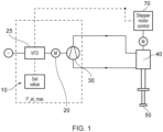
- FIG. 1 shows a cryogenic system according to an embodiment.
- the cryogenic refrigeration system comprises control circuitry 10 configured to control a motor 20 driving a compressor 30 compressing the refrigerant in the refrigeration system.
- the control circuitry 10 also controls motor 70 which drives an inlet valve, not shown, controlling the supply of higher pressure refrigerant to the refrigeration unit or coldhead 40.
- the control circuitry 10 comprises a data store that stores a threshold value for setting a maximum value for the power and/or electric current supplied to the compressor.
- the refrigeration unit 40 comprises a Gifford McMahon refrigerator unit (this Gifford McMahon piston system is hereinafter designated as the "coldhead") and the compressor 30 supplies pressurized helium as the cryogenic agent or refrigerant.
- the system is a hermetically sealed system with a closed refrigerant cycle.
- the control system 10 is provided, and this allows the measurement and regulation of variable frequency drive output electric current and / or electric power supplied to the compressor motor 20.
- Maintaining the power consumption of the compressor 30 below a threshold value allows the refrigeration system to be configured with a higher initial filling pressure of refrigerant as this is no longer limited by the power consumed by the compressor running at maximum speed during the cooldown process.
- the compressor motor 20 is directly connected to a variable frequency drive (VFD) 25 supplying power to the compressor and controlled by the control circuitry 10.
- VFD variable frequency drive
- This electrical current and/or electrical power control will affect the output frequency of the VFD and thus, the speed of rotation of the compressor motor.
- This control circuitry 10 seeks to adjust the compressor revolution speed to close to the maximum allowed electrical load of the windings of the motor 20 without danger of thermal switch off.
- the reason for this may be the rising dissipation of energy in the system at higher compressor speeds which will immediately cause performance loss. Therefore it may not be desirable to run the compressor at the highest possible speed allowed for a particular threshold power and a maximum possible differential pressure in the system and with appropriate measurement and control a preferred operating point with a lower frequency may be found.
- this current / power control system 10 can also be used for limiting the energy demand of the cryogenic system in the steady state under partial load conditions. In this case an additional set point or threshold value corresponding to lower winding current / electric power may be used. In this way an energy save mode can be supported using the same control circuitry.
- Figure 2 shows the operation of embodiments compared to conventional refrigeration systems.
- the left-hand side graphs shows the operation of a conventional system whereas the right-hand side graphs shows the operation of a refrigeration system according to an embodiment.
- the upper left-hand graph shows how the pressure in a conventional system is lower initially prior to switch on, and then following switch on both the high pressure line and the low pressure line have pressures which gradually decrease as the temperature drops and refrigerant accumulates in the coldest part of the system.
- the initial refrigerant pressure is higher as the system is "over-filled”.
- the compressor speed is limited at switch on so the high and low pressure lines take time to reach a steady state value. Once attained these pressures are maintained and the higher pressure is higher than the higher pressure in the conventional system due to the initial overfilling.
- compressor power is shown to decrease over time in a conventional refrigeration system after start up as the pressure in the system reduces due to the accumulation of the refrigerant in the coldest part of the coldhead.
- the right-hand graph shows how the power supplied to the compressor is reduced initially during cooldown and this corresponds to a lower compressor speed.
- the power gradually increases to a maximum power which can be maintained once the system reaches the steady state.
- This maximum power that the compressor can safely cope with is in both embodiments 8.3KW, however, by control of the compressor during cooldown in an embodiment, this higher power can be applied to the compressor in the steady state without overloading the compressor during cooldown.
- the third pair of graphs show how the frequency of operation of the compressor varies for a conventional refrigeration system and that of an embodiment.
- the refrigeration system of an embodiment has a reduced frequency of operation of the compressor initially which increases to the full maximum speed or close to the full maximum speed once cooldown has finished.
- the compressor of the prior art has the single speed of operation.
- the final two graphs show how an embodiment provides an improved coldhead power due to the increased mass flow rate of the refrigerant that embodiments can provide either by overfilling the system or providing an additional volume.
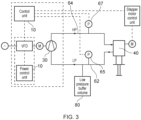
- Figure 3 shows an alternative embodiment of a refrigeration system which has a low pressure buffer volume 80 connected to low pressure line 62 which line returns refrigerant from the refrigeration unit 40 to the compressor 30.
- a pressure sensor 65 for sensing the pressure of the low pressure line 62
- an additional pressure sensor 67 for sensing the pressure of the high pressure line 64.
- a differential pressure sensor may be used instead of high and low pressure sensors.
- control circuitry 10 controls both the compressor speed by controlling the frequency of rotation of the motor driving the compressor in dependence upon a power threshold, and the frequency of rotation of the inlet value for supplying high pressure refrigerant from the higher pressure refrigerant line 64 to the refrigeration unit or coldhead 40.
- Operation of the refrigeration system starts with the compressor driven at an initially lower frequency while the pressure of the refrigerant is higher, the frequency of operation being set by the threshold power limit of the compressor motor controlled by control circuitry 10.
- the control circuitry detects this and increases the frequency and the revolution speed which leads to increased motor winding current and power consumption such that power consumption is kept close to the threshold level in some embodiments within 2% of this value, in others within 5% and in still others within 10% of the threshold power level.
- the pressure of the refrigerant falls the speed of the motor increases while the power consumed by the motor is maintained below but close to the threshold value.
- control circuitry 10 controlling the inlet valve for the coldhead 40. Controlling the inlet valve controls the differential pressure of the refrigeration system which again affects the cooling of the refrigeration system.
- the compressor may operate effectively within certain high and low pressure limits, which for a scroll compressor may be defined in a scroll performance map which sets limit values for the high and low pressure lines that the compressor can operate effectively within.
- control unit 10 may be used to control the speed of operation of the compressor not only to ensure that maximum power consumption is not exceeded but also to ensure that the high and low pressure limits of the scroll performance map are not breeched.
- control unit 10 receives signals from the pressure sensors 65 and 67 and in response to either of these indicating that the pressure in the high and/or low pressure lines are moving towards a limit value, the control unit may amend the speed of operation of the compressor to bring the pressures away from these limit values. In some embodiments the control unit 10 may control one or both of the inlet valve and the speed of the compressor to maintain the operation of the compressor within the desired pressure limits.
- this embodiment there is a low pressure buffer volume 80 which allows additional refrigerant to be supplied to the system without increasing the pressure within the system to beyond that that the scroll compressor 30 can operate effectively at. In this way this embodiment adjusts the volume ratio between high and low pressure and increases the amount of refrigerant in the system without increasing the filling pressure. This is an alternative option to increasing the filling pressure of the refrigerant (although it may be used in conjunction with this option).
- Both options for increasing the refrigerant amount may be used to adjust the operating conditions of the refrigeration unit to increase the cooling power and/or the efficiency of the system.
- the technical limit for increasing the cooling power is the electrical power consumption of the compressor which will lead to high currents in the windings of the compressor motor. Where these become too high a thermal protection switch (circuit breaker) will operate and shut down the compressor motor. This should be avoided for safe and stable operation of the system.
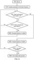
- Figure 4 schematically shows a flow diagram illustrating steps in a method according to an embodiment.
- Start up occurs at step S0 which may be initial start up or start up following a break in the refrigeration cycle.
- the compressor motor is powered to operate at a first initial reduced frequency at step S10.
- the power consumed by the motor may be assessed continually, and this is shown at steps D5 and D15 and if it is below the threshold value Pt by more than a certain amount ⁇ P then the frequency of rotation of the motor is increased at step S20. If it is above the threshold Pt then the frequency of rotation is reduced at step S30. If it is within the range required then no change is made to the frequency of rotation.
- step S20 Following an increase in the frequency of rotation at step S20 perhaps to or close to the maximum frequency of rotation, it is determined whether the cool down process is complete at step D25 and if it is then steady state operation is started.
Landscapes
- Engineering & Computer Science (AREA)
- Mechanical Engineering (AREA)
- General Engineering & Computer Science (AREA)
- Physics & Mathematics (AREA)
- Thermal Sciences (AREA)
- Control Of Positive-Displacement Pumps (AREA)
Claims (14)
- Kryogenes Kühlsystem, umfassend:eine Kühleinheit, umfassend eine Expansionseinheit;einen Kompressor mit variabler Drehzahl, dazu ausgestaltet, Kältemittel zu verdichten, wobei der Kompressor mit variabler Drehzahl dazu ausgestaltet ist, Kältemittel über eine Leitung mit niedrigerem Druck von der Kühleinheit aufzunehmen und der Kühleinheit verdichtetes Kältemittel über eine Leitung mit höherem Druck zuzuführen; undeine Steuerschaltung, dazu ausgestaltet, den Kompressor mit variabler Drehzahl so zu steuern, dass ein Energieverbrauch des Kompressors mit variabler Drehzahl unter einem vorbestimmten Schwellenwert liegt, indem während des Abkühlens der Kompressor so gesteuert wird, dass er anfänglich bei einer reduzierten Frequenz arbeitet und später eine Frequenz des Betriebs des Kompressors mit variabler Drehzahl so erhöht wird, dass der Kompressor mit variabler Drehzahl bei einer höheren Frequenz arbeitet.
- Kryogenes Kühlsystem nach Anspruch 1, wobei
dem kryogenen Kühlsystems zusätzliches Kältemittel bereitgestellt wird durch:Erhöhen eines anfänglichen Fülldrucks, sodass ein Betrieb des Kompressors mit variabler Drehzahl bei voller Drehzahl während des Abkühlens der Kühleinheit dazu führen würde, dass der Kompressor mit variabler Drehzahl Energie oberhalb des vorbestimmten Schwellenwertes verbraucht; und/oderBereitstellen eine Puffervolumens von Kältemittel in Fluidaustausch mit der Leitung mit niedrigerem Druck. - Kryogenes Kühlsystem nach Anspruch 1 oder 2, wobei die Steuerschaltung ferner dazu ausgestaltet ist, den Kompressor mit variabler Drehzahl so zu steuern, dass der Druck der Leitung mit höherem Druck und der Leitung mit niedrigerem Druck innerhalb vorbestimmter Grenzwerte gehalten wird.
- Kryogenes Kühlsystem nach einer der vorhergehenden Ansprüche, wobei die Steuerschaltung dazu ausgestaltet ist, die Frequenz des Betriebs des Kompressors mit variabler Drehzahl in Reaktion auf einen erkannten Rückgang des Energieverbrauchs des Kompressors mit variabler Drehzahl zu erhöhen.
- Kryogenes Kühlsystem nach einem der vorangehenden Ansprüche, wobei die anfängliche reduzierte Frequenz des Betriebs des Kompressors weniger als 70 0 0einer maximalen Betriebsfrequenz während eines Dauerbetriebs der Kühleinheit, vorzugsweise weniger als 60 0 0, beträgt.
- Kryogenes Kühlsystem nach einem der vorangehenden Ansprüche, wobei die maximale Betriebsfrequenz während Dauerbetrieb zwischen 50 und 70 Hz beträgt und die anfängliche Betriebsfrequenz während des Abkühlens niedriger ist, vorzugsweise zwischen 30 und 50 Hz.
- Kryogenes Kühlsystem nach einem der vorangehenden Ansprüche, wobei das Kältemittel Helium umfasst.
- Kryogenes Kühlsystem nach einem der vorangehenden Ansprüche, wobei die Kühleinheit dazu ausgestaltet ist, auf unter 80 K, vorzugsweise auf unter 50 K, stärker bevorzugt auf unter 10 K, stärker bevorzugt auf unter 4 K, zu kühlen.
- Kryogenes Kühlsystem nach Anspruch 2 oder einem der Ansprüche 3 bis 8, wenn abhängig von Anspruch 2, wobei ein Anfangsdruck des Kältemittels 5 0 0, vorzugsweise 10 0 0höher als für die Kühleinheit spezifiziert ist, wobei während des Abkühlens keine Leistungssteuerung des Kompressors mit variabler Drehzahl erfolgt.
- Kryogenes Kühlsystem nach Anspruch 2 oder einem der Ansprüche 3 bis 8, wenn abhängig von Anspruch 2, wobei das Kühlsystem ferner das Puffervolumen von Kältemittel umfasst, wobei das Puffervolumen mehr als 20 0 0einer Gesamtmenge von Kältemittel innerhalb des Kühlsystems, vorzugsweise mehr als 50 0 0, in einigen Fällen mehr als 90 0 0, umfasst.
- Kryogenes Kühlsystem nach einem der vorangehenden Ansprüche, wobei die Steuerschaltung ferner dazu ausgestaltet ist, den Kompressor mit variabler Drehzahl in einem Energiesparmodus zu steuern, um einen Energieverbrauch des Kompressors mit variabler Drehzahl unter einem vorbestimmten reduzierten Schwellenwert zu halten.
- Kryopumpe, umfassend ein kryogenes Kühlsystem nach einem der vorangehenden Ansprüche.
- Verfahren zum Betreiben eines kryogenes Kühlsystems, umfassend eine Kühleinheit, die eine Expansionseinheit und einen Kompressor mit variabler Drehzahl umfasst, dazu ausgestaltet, ein Kältemittel zu verdichten, sodass ein Kältemittel mit höherem Druck der Kühleinheit zugeführt wird und ein Kältemittel mit niedrigerem Druck von der Kühleinheit aufgenommen wird, wobei das Verfahren umfasst:während eines anfänglichen Abkühlens der Kühleinheit Betreiben des Kompressors mit einer anfänglich niedrigeren Frequenz, um eine von dem Kompressor mit variabler Drehzahl verbrauchte Energie unter einem vorbestimmten Schwellenwert zu halten; undspäter Erhöhen einer Betriebsfrequenz des Kompressors auf eine volle Betriebsdrehzahl.
- Verfahren nach Anspruch 13, wobei das Verfahren ferner einen ersten Schritt des Versorgens des Kühlsystems mit einer erhöhten Menge von Kältemittel umfasst, und zwar durch:Erhöhen eines Fülldrucks von Kältemittel in dem System, sodass der Betrieb des Kompressors mit variabler Drehzahl während des Abkühlens bei einer maximalen Betriebsfrequenz den vorbestimmten Schwellenwert für den Energieverbrauch überschreiten würde; und/oderBereitstellen eine Puffervolumens von zusätzlichem Kältemittel in Fluidaustausch mit der Leitung mit niedrigerem Druck.
Applications Claiming Priority (3)
| Application Number | Priority Date | Filing Date | Title |
|---|---|---|---|
| EP20217269 | 2020-12-24 | ||
| GB2101714.0A GB2602515A (en) | 2020-12-24 | 2021-02-08 | Cryogenic refrigeration system and cryogenic pump |
| PCT/EP2021/087265 WO2022136534A1 (en) | 2020-12-24 | 2021-12-22 | Cryogenic refrigeration system and cryogenic pump |
Publications (2)
| Publication Number | Publication Date |
|---|---|
| EP4267895A1 EP4267895A1 (de) | 2023-11-01 |
| EP4267895B1 true EP4267895B1 (de) | 2025-02-05 |
Family
ID=80112220
Family Applications (1)
| Application Number | Title | Priority Date | Filing Date |
|---|---|---|---|
| EP21843980.0A Active EP4267895B1 (de) | 2020-12-24 | 2021-12-22 | Kryogenes kühlsystem und kryogene pumpe |
Country Status (6)
| Country | Link |
|---|---|
| US (1) | US12584670B2 (de) |
| EP (1) | EP4267895B1 (de) |
| JP (1) | JP7705958B2 (de) |
| CN (1) | CN116710716B (de) |
| TW (1) | TW202238049A (de) |
| WO (1) | WO2022136534A1 (de) |
Families Citing this family (2)
| Publication number | Priority date | Publication date | Assignee | Title |
|---|---|---|---|---|
| JP7705958B2 (ja) * | 2020-12-24 | 2025-07-10 | ライボルト ドレスデン ゲゼルシャフト ミット ベシュレンクテル ハフツング | 極低温冷凍システム及び極低温ポンプ |
| CN115325287B (zh) * | 2022-09-13 | 2024-07-30 | 西南石油大学 | 一种复合能源管道传输特性分析方法 |
Family Cites Families (32)
| Publication number | Priority date | Publication date | Assignee | Title |
|---|---|---|---|---|
| US4809154A (en) * | 1986-07-10 | 1989-02-28 | Air Products And Chemicals, Inc. | Automated control system for a multicomponent refrigeration system |
| JPS6346351A (ja) * | 1986-08-12 | 1988-02-27 | 株式会社東芝 | 極低温冷凍機 |
| US5651667A (en) * | 1991-10-11 | 1997-07-29 | Helix Technology Corporation | Cryopump synchronous motor load monitor |
| JPH05113259A (ja) | 1991-10-22 | 1993-05-07 | Sanyo Electric Co Ltd | 極低温冷凍装置 |
| JPH09303897A (ja) * | 1996-05-10 | 1997-11-28 | Daikin Ind Ltd | 極低温冷凍装置 |
| JP2002106991A (ja) | 2000-09-29 | 2002-04-10 | Sanyo Electric Co Ltd | ヘリウム圧縮機ユニット |
| US7127901B2 (en) * | 2001-07-20 | 2006-10-31 | Brooks Automation, Inc. | Helium management control system |
| US7555911B2 (en) * | 2002-08-20 | 2009-07-07 | Sumitomo Heavy Industries, Ltd. | Cryogenic refrigerator |
| US20090025422A1 (en) * | 2007-07-25 | 2009-01-29 | Air Products And Chemicals, Inc. | Controlling Liquefaction of Natural Gas |
| GB2453721B (en) * | 2007-10-15 | 2010-11-17 | Siemens Magnet Technology Ltd | Helium compressor with control for reduced power consumption |
| US20120036888A1 (en) * | 2007-11-05 | 2012-02-16 | David Vandor | Method and system for the small-scale production of liquified natural gas (lng) and cold compressed gas (ccng) from low-pressure natural gas |
| GB2455737B (en) | 2007-12-19 | 2010-08-11 | Siemens Magnet Technology Ltd | Variable charge compressor |
| BRPI0907488B8 (pt) * | 2008-02-08 | 2020-08-18 | Shell Int Research | aparelho para resfriar um trocador de calor criogênico, método para resfriar um trocador de calor criogênico, e, métodos de liquefação de uma corrente de hidrocarboneto |
| US8794016B2 (en) * | 2008-08-14 | 2014-08-05 | Raytheon Company | Monitoring the health of a cryocooler |
| KR101342455B1 (ko) * | 2010-10-08 | 2013-12-17 | 스미토모 크라이어제닉스 오브 아메리카 인코포레이티드 | 고속 냉각 극저온 냉동기 |
| TWI705187B (zh) * | 2011-03-04 | 2020-09-21 | 美商艾德華真空有限責任公司 | 低溫冷凍系統以及用於控制氦氣冷凍劑之供給的方法 |
| WO2012122144A1 (en) | 2011-03-07 | 2012-09-13 | Wu Nian | Highly monodisperse branched peg-lipid conjugates |
| GB2496573B (en) | 2011-09-27 | 2016-08-31 | Oxford Instr Nanotechnology Tools Ltd | Apparatus and method for controlling a cryogenic cooling system |
| JP5943865B2 (ja) * | 2013-03-12 | 2016-07-05 | 住友重機械工業株式会社 | クライオポンプシステム、クライオポンプシステムの運転方法、及び圧縮機ユニット |
| JP2015098844A (ja) * | 2013-11-20 | 2015-05-28 | 住友重機械工業株式会社 | クライオポンプシステム、及びクライオポンプシステムの運転方法 |
| JP6180349B2 (ja) * | 2014-03-18 | 2017-08-16 | 住友重機械工業株式会社 | 極低温冷凍機および極低温冷凍機の制御方法 |
| US20180017320A1 (en) * | 2014-12-29 | 2018-01-18 | Shell Oil Company | Method and apparatus for cooling down a cryogenic heat exchanger and method of liquefying a hydrocarbon stream |
| CN105890268B (zh) * | 2015-02-13 | 2020-07-10 | 旺矽科技股份有限公司 | 具有除霜功能的冷却系统 |
| JP6443557B2 (ja) * | 2015-09-15 | 2018-12-26 | 株式会社デンソー | 複数段圧縮式冷凍サイクル装置 |
| US10393429B2 (en) * | 2016-04-06 | 2019-08-27 | Air Products And Chemicals, Inc. | Method of operating natural gas liquefaction facility |
| WO2018071884A1 (en) * | 2016-10-14 | 2018-04-19 | Supercritical Fluid Technologies, Inc. | Cooling loop with a supercritical fluid system using compressed refrigerant fluid flow with a positive joule-thomson coefficient |
| JP6975077B2 (ja) * | 2018-03-07 | 2021-12-01 | 住友重機械工業株式会社 | 極低温冷凍機および極低温冷凍機の給電系統 |
| KR102033991B1 (ko) * | 2019-04-04 | 2019-11-08 | 주식회사 휘온 | 크라이오 펌프시스템용 헬륨 컴프레서의 전력 절감 장치 및 이를 이용한 전력 절감 방법 |
| US12181216B2 (en) * | 2020-09-04 | 2024-12-31 | Honeywell Lng Llc | Method to control the cooldown of main heat exchangers in liquefied natural gas plant |
| WO2022064989A1 (ja) * | 2020-09-25 | 2022-03-31 | 住友重機械工業株式会社 | 極低温冷凍機、および極低温冷凍機の監視方法 |
| JP7705958B2 (ja) * | 2020-12-24 | 2025-07-10 | ライボルト ドレスデン ゲゼルシャフト ミット ベシュレンクテル ハフツング | 極低温冷凍システム及び極低温ポンプ |
| US12007165B2 (en) * | 2021-06-07 | 2024-06-11 | Saudi Arabian Oil Company | Optimized natural gas production control system with actual flow and set point tracking features |
-
2021
- 2021-12-22 JP JP2023563153A patent/JP7705958B2/ja active Active
- 2021-12-22 CN CN202180087628.8A patent/CN116710716B/zh active Active
- 2021-12-22 EP EP21843980.0A patent/EP4267895B1/de active Active
- 2021-12-22 US US18/258,961 patent/US12584670B2/en active Active
- 2021-12-22 WO PCT/EP2021/087265 patent/WO2022136534A1/en not_active Ceased
- 2021-12-24 TW TW110148583A patent/TW202238049A/zh unknown
Also Published As
| Publication number | Publication date |
|---|---|
| JP2024501902A (ja) | 2024-01-16 |
| CN116710716A (zh) | 2023-09-05 |
| WO2022136534A1 (en) | 2022-06-30 |
| US12584670B2 (en) | 2026-03-24 |
| JP7705958B2 (ja) | 2025-07-10 |
| TW202238049A (zh) | 2022-10-01 |
| CN116710716B (zh) | 2025-10-21 |
| US20240302088A1 (en) | 2024-09-12 |
| EP4267895A1 (de) | 2023-11-01 |
Similar Documents
| Publication | Publication Date | Title |
|---|---|---|
| US6076367A (en) | Variable speed liquid refrigerant pump | |
| EP2616749B1 (de) | System und verfahren zur steuerung einer economizer-schaltung | |
| US8601828B2 (en) | Capacity control systems and methods for a compressor | |
| EP2761236B1 (de) | Vorrichtung und verfahren zum steuern eines kryokühlsystems | |
| EP3055627A1 (de) | Temperatursteuerungssystem für motorgehäuse | |
| US12584670B2 (en) | Cryogenic refrigeration system and cryogenic pump | |
| WO2013012491A1 (en) | Compressor clearance control | |
| JP2012072920A (ja) | 冷凍装置 | |
| US10180138B2 (en) | Compressor temperature control systems and methods | |
| GB2602515A (en) | Cryogenic refrigeration system and cryogenic pump | |
| JP4767133B2 (ja) | 冷凍サイクル装置 | |
| JP5959373B2 (ja) | 冷凍装置 | |
| JP6076136B2 (ja) | 冷凍装置 | |
| WO2022118729A1 (ja) | 冷凍機及び冷凍機の予冷時の運転方法 | |
| JP2510534B2 (ja) | 冷凍設備の制御装置 | |
| JP4690574B2 (ja) | 冷凍機における膨張弁の制御方法及び制御装置 | |
| JP4146770B2 (ja) | 電力貯蔵装置 | |
| CN120557818A (zh) | 冷水机组的控制方法及冷水机组 | |
| CN115371313A (zh) | 一种制冷机控制方法及制冷机 | |
| JP2009250140A (ja) | 冷凍装置 |
Legal Events
| Date | Code | Title | Description |
|---|---|---|---|
| STAA | Information on the status of an ep patent application or granted ep patent |
Free format text: STATUS: UNKNOWN |
|
| STAA | Information on the status of an ep patent application or granted ep patent |
Free format text: STATUS: THE INTERNATIONAL PUBLICATION HAS BEEN MADE |
|
| PUAI | Public reference made under article 153(3) epc to a published international application that has entered the european phase |
Free format text: ORIGINAL CODE: 0009012 |
|
| STAA | Information on the status of an ep patent application or granted ep patent |
Free format text: STATUS: REQUEST FOR EXAMINATION WAS MADE |
|
| 17P | Request for examination filed |
Effective date: 20230619 |
|
| AK | Designated contracting states |
Kind code of ref document: A1 Designated state(s): AL AT BE BG CH CY CZ DE DK EE ES FI FR GB GR HR HU IE IS IT LI LT LU LV MC MK MT NL NO PL PT RO RS SE SI SK SM TR |
|
| DAV | Request for validation of the european patent (deleted) | ||
| DAX | Request for extension of the european patent (deleted) | ||
| GRAP | Despatch of communication of intention to grant a patent |
Free format text: ORIGINAL CODE: EPIDOSNIGR1 |
|
| STAA | Information on the status of an ep patent application or granted ep patent |
Free format text: STATUS: GRANT OF PATENT IS INTENDED |
|
| INTG | Intention to grant announced |
Effective date: 20240716 |
|
| GRAS | Grant fee paid |
Free format text: ORIGINAL CODE: EPIDOSNIGR3 |
|
| P01 | Opt-out of the competence of the unified patent court (upc) registered |
Free format text: CASE NUMBER: APP_60843/2024 Effective date: 20241112 |
|
| GRAA | (expected) grant |
Free format text: ORIGINAL CODE: 0009210 |
|
| STAA | Information on the status of an ep patent application or granted ep patent |
Free format text: STATUS: THE PATENT HAS BEEN GRANTED |
|
| AK | Designated contracting states |
Kind code of ref document: B1 Designated state(s): AL AT BE BG CH CY CZ DE DK EE ES FI FR GB GR HR HU IE IS IT LI LT LU LV MC MK MT NL NO PL PT RO RS SE SI SK SM TR |
|
| REG | Reference to a national code |
Ref country code: GB Ref legal event code: FG4D |
|
| REG | Reference to a national code |
Ref country code: CH Ref legal event code: EP |
|
| REG | Reference to a national code |
Ref country code: IE Ref legal event code: FG4D |
|
| REG | Reference to a national code |
Ref country code: DE Ref legal event code: R096 Ref document number: 602021025817 Country of ref document: DE |
|
| REG | Reference to a national code |
Ref country code: NL Ref legal event code: MP Effective date: 20250205 |
|
| PG25 | Lapsed in a contracting state [announced via postgrant information from national office to epo] |
Ref country code: RS Free format text: LAPSE BECAUSE OF FAILURE TO SUBMIT A TRANSLATION OF THE DESCRIPTION OR TO PAY THE FEE WITHIN THE PRESCRIBED TIME-LIMIT Effective date: 20250505 |
|
| PG25 | Lapsed in a contracting state [announced via postgrant information from national office to epo] |
Ref country code: FI Free format text: LAPSE BECAUSE OF FAILURE TO SUBMIT A TRANSLATION OF THE DESCRIPTION OR TO PAY THE FEE WITHIN THE PRESCRIBED TIME-LIMIT Effective date: 20250205 |
|
| PG25 | Lapsed in a contracting state [announced via postgrant information from national office to epo] |
Ref country code: PL Free format text: LAPSE BECAUSE OF FAILURE TO SUBMIT A TRANSLATION OF THE DESCRIPTION OR TO PAY THE FEE WITHIN THE PRESCRIBED TIME-LIMIT Effective date: 20250205 |
|
| PG25 | Lapsed in a contracting state [announced via postgrant information from national office to epo] |
Ref country code: ES Free format text: LAPSE BECAUSE OF FAILURE TO SUBMIT A TRANSLATION OF THE DESCRIPTION OR TO PAY THE FEE WITHIN THE PRESCRIBED TIME-LIMIT Effective date: 20250205 |
|
| REG | Reference to a national code |
Ref country code: LT Ref legal event code: MG9D |
|
| PG25 | Lapsed in a contracting state [announced via postgrant information from national office to epo] |
Ref country code: IS Free format text: LAPSE BECAUSE OF FAILURE TO SUBMIT A TRANSLATION OF THE DESCRIPTION OR TO PAY THE FEE WITHIN THE PRESCRIBED TIME-LIMIT Effective date: 20250605 Ref country code: NO Free format text: LAPSE BECAUSE OF FAILURE TO SUBMIT A TRANSLATION OF THE DESCRIPTION OR TO PAY THE FEE WITHIN THE PRESCRIBED TIME-LIMIT Effective date: 20250505 |
|
| PG25 | Lapsed in a contracting state [announced via postgrant information from national office to epo] |
Ref country code: NL Free format text: LAPSE BECAUSE OF FAILURE TO SUBMIT A TRANSLATION OF THE DESCRIPTION OR TO PAY THE FEE WITHIN THE PRESCRIBED TIME-LIMIT Effective date: 20250205 |
|
| PG25 | Lapsed in a contracting state [announced via postgrant information from national office to epo] |
Ref country code: HR Free format text: LAPSE BECAUSE OF FAILURE TO SUBMIT A TRANSLATION OF THE DESCRIPTION OR TO PAY THE FEE WITHIN THE PRESCRIBED TIME-LIMIT Effective date: 20250205 |
|
| PG25 | Lapsed in a contracting state [announced via postgrant information from national office to epo] |
Ref country code: LV Free format text: LAPSE BECAUSE OF FAILURE TO SUBMIT A TRANSLATION OF THE DESCRIPTION OR TO PAY THE FEE WITHIN THE PRESCRIBED TIME-LIMIT Effective date: 20250205 Ref country code: PT Free format text: LAPSE BECAUSE OF FAILURE TO SUBMIT A TRANSLATION OF THE DESCRIPTION OR TO PAY THE FEE WITHIN THE PRESCRIBED TIME-LIMIT Effective date: 20250605 |
|
| PG25 | Lapsed in a contracting state [announced via postgrant information from national office to epo] |
Ref country code: GR Free format text: LAPSE BECAUSE OF FAILURE TO SUBMIT A TRANSLATION OF THE DESCRIPTION OR TO PAY THE FEE WITHIN THE PRESCRIBED TIME-LIMIT Effective date: 20250506 Ref country code: BG Free format text: LAPSE BECAUSE OF FAILURE TO SUBMIT A TRANSLATION OF THE DESCRIPTION OR TO PAY THE FEE WITHIN THE PRESCRIBED TIME-LIMIT Effective date: 20250205 |
|
| REG | Reference to a national code |
Ref country code: AT Ref legal event code: MK05 Ref document number: 1764947 Country of ref document: AT Kind code of ref document: T Effective date: 20250205 |
|
| PG25 | Lapsed in a contracting state [announced via postgrant information from national office to epo] |
Ref country code: SE Free format text: LAPSE BECAUSE OF FAILURE TO SUBMIT A TRANSLATION OF THE DESCRIPTION OR TO PAY THE FEE WITHIN THE PRESCRIBED TIME-LIMIT Effective date: 20250205 |
|
| PG25 | Lapsed in a contracting state [announced via postgrant information from national office to epo] |
Ref country code: SM Free format text: LAPSE BECAUSE OF FAILURE TO SUBMIT A TRANSLATION OF THE DESCRIPTION OR TO PAY THE FEE WITHIN THE PRESCRIBED TIME-LIMIT Effective date: 20250205 |
|
| PG25 | Lapsed in a contracting state [announced via postgrant information from national office to epo] |
Ref country code: DK Free format text: LAPSE BECAUSE OF FAILURE TO SUBMIT A TRANSLATION OF THE DESCRIPTION OR TO PAY THE FEE WITHIN THE PRESCRIBED TIME-LIMIT Effective date: 20250205 |
|
| PG25 | Lapsed in a contracting state [announced via postgrant information from national office to epo] |
Ref country code: IT Free format text: LAPSE BECAUSE OF FAILURE TO SUBMIT A TRANSLATION OF THE DESCRIPTION OR TO PAY THE FEE WITHIN THE PRESCRIBED TIME-LIMIT Effective date: 20250205 |
|
| PG25 | Lapsed in a contracting state [announced via postgrant information from national office to epo] |
Ref country code: AT Free format text: LAPSE BECAUSE OF FAILURE TO SUBMIT A TRANSLATION OF THE DESCRIPTION OR TO PAY THE FEE WITHIN THE PRESCRIBED TIME-LIMIT Effective date: 20250205 |
|
| PG25 | Lapsed in a contracting state [announced via postgrant information from national office to epo] |
Ref country code: EE Free format text: LAPSE BECAUSE OF FAILURE TO SUBMIT A TRANSLATION OF THE DESCRIPTION OR TO PAY THE FEE WITHIN THE PRESCRIBED TIME-LIMIT Effective date: 20250205 |
|
| PG25 | Lapsed in a contracting state [announced via postgrant information from national office to epo] |
Ref country code: RO Free format text: LAPSE BECAUSE OF FAILURE TO SUBMIT A TRANSLATION OF THE DESCRIPTION OR TO PAY THE FEE WITHIN THE PRESCRIBED TIME-LIMIT Effective date: 20250205 |
|
| PG25 | Lapsed in a contracting state [announced via postgrant information from national office to epo] |
Ref country code: SK Free format text: LAPSE BECAUSE OF FAILURE TO SUBMIT A TRANSLATION OF THE DESCRIPTION OR TO PAY THE FEE WITHIN THE PRESCRIBED TIME-LIMIT Effective date: 20250205 |
|
| REG | Reference to a national code |
Ref country code: DE Ref legal event code: R097 Ref document number: 602021025817 Country of ref document: DE |
|
| PLBE | No opposition filed within time limit |
Free format text: ORIGINAL CODE: 0009261 |
|
| STAA | Information on the status of an ep patent application or granted ep patent |
Free format text: STATUS: NO OPPOSITION FILED WITHIN TIME LIMIT |
|
| PGFP | Annual fee paid to national office [announced via postgrant information from national office to epo] |
Ref country code: GB Payment date: 20251229 Year of fee payment: 5 |
|
| 26N | No opposition filed |
Effective date: 20251106 |
|
| PGFP | Annual fee paid to national office [announced via postgrant information from national office to epo] |
Ref country code: FR Payment date: 20251226 Year of fee payment: 5 |
|
| PGFP | Annual fee paid to national office [announced via postgrant information from national office to epo] |
Ref country code: CZ Payment date: 20251210 Year of fee payment: 5 |
|
| PGFP | Annual fee paid to national office [announced via postgrant information from national office to epo] |
Ref country code: DE Payment date: 20251229 Year of fee payment: 5 |