EP4268570B1 - Moissonneuse-batteuse automotrice - Google Patents
Moissonneuse-batteuse automotrice Download PDFInfo
- Publication number
- EP4268570B1 EP4268570B1 EP23155731.5A EP23155731A EP4268570B1 EP 4268570 B1 EP4268570 B1 EP 4268570B1 EP 23155731 A EP23155731 A EP 23155731A EP 4268570 B1 EP4268570 B1 EP 4268570B1
- Authority
- EP
- European Patent Office
- Prior art keywords
- combine harvester
- guide plate
- opening
- fruits
- threshing
- Prior art date
- Legal status (The legal status is an assumption and is not a legal conclusion. Google has not performed a legal analysis and makes no representation as to the accuracy of the status listed.)
- Active
Links
Images


Classifications
-
- A—HUMAN NECESSITIES
- A01—AGRICULTURE; FORESTRY; ANIMAL HUSBANDRY; HUNTING; TRAPPING; FISHING
- A01F—PROCESSING OF HARVESTED PRODUCE; HAY OR STRAW PRESSES; DEVICES FOR STORING AGRICULTURAL OR HORTICULTURAL PRODUCE
- A01F12/00—Parts or details of threshing apparatus
- A01F12/48—Air conduits or blowers for grain
-
- A—HUMAN NECESSITIES
- A01—AGRICULTURE; FORESTRY; ANIMAL HUSBANDRY; HUNTING; TRAPPING; FISHING
- A01F—PROCESSING OF HARVESTED PRODUCE; HAY OR STRAW PRESSES; DEVICES FOR STORING AGRICULTURAL OR HORTICULTURAL PRODUCE
- A01F12/00—Parts or details of threshing apparatus
- A01F12/44—Grain cleaners; Grain separators
- A01F12/444—Fanning means
Definitions
- the present application relates to a self-propelled combine harvester according to the preamble of claim 1.
- a significant portion of the fruits, as well as fine plant residues, can be separated directly in the area of the threshing unit by means of a threshing concave, with the fruits being guided downwards from the threshing unit onto a preparation floor. Furthermore, a mixture of fruit and plant residues is passed from the threshing unit to a separating unit, which separates at least coarse plant residues from the fruit and fine plant residues.
- the plant residues are typically ejected from the rear of the combine harvester, where they may have been chopped beforehand by a chopping unit.
- the fruit and fine plant residue separated by the separating device are passed to a sieve device, which sieves out the remaining fine plant residue.
- the fruit and fine plant residue already separated by the threshing device's concave are also fed to the sieve device. These are then conveyed to the sieve device via the preparation floor.
- suction fan One suction side of this suction fan is assigned to the sieve assembly, so that the suction fan is suitable for directing the air flow from an air inlet cross-section located in front of the sieve assembly, viewed in the longitudinal direction of the combine harvester, along the sieve assembly, so that the fine plant residues can be captured and removed as desired.
- the crops sieved in this way by the sieve assembly are usually conveyed into a grain tank by an elevator.
- Combine harvesters of the type described above are already known in the prior art. Reference is made, for example, to the German patent application DE 24 19 141 A1 This describes a stone trap for a combine harvester, which is located between the feederhouse and the threshing unit.
- Another combine harvester is for example from EP3662738 A1 known.
- the combine harvester according to the invention is characterized in that the air inlet cross-section is formed on an air inlet structure arranged between the threshing element and the preparation floor.
- the air volume flow sucked in through this air inlet cross-section is guided along the preparation floor to the sieve element and finally to the suction fan, by means of which the air volume flow can be sucked in and which is assigned to the rear end of the sieve element.
- the air inlet structure comprises a trickle grain guard, which has a The unwanted escape of fruit through the air inlet cross-section is reduced. This escape is preferably completely prevented by the trickle grain guard.
- the combine harvester according to the invention has many advantages.
- it allows the air flow to enter the area between the inclined conveyor and the preparation floor, so that the above-described cleaning effect of the air flow, which consists in mobilizing the fine plant residues, can already take effect in the preparation floor area.
- the air inlet structure which features the described anti-trickle grain protection, reduces the escape of crops through the air inlet cross-section.
- the trickle grain guard is designed in the manner of a labyrinth seal, which prevents fruit that is accelerated in an unfavorable manner in the direction of the air inlet cross-section from leaving the area of the preparation floor through the air inlet cross-section along an unaffected trajectory.
- the labyrinth seal ensures that a connecting path between an outer region, from which the air volume flow is sucked in, and the area of the preparation floor has at least one, preferably a plurality of deflections. This ensures that a respective fruit impacts a component of the trickle grain guard at least at one point and is thus very likely prevented from undesirably escaping from the area of the preparation floor.
- the air volume flow that is sucked in through the air inlet cross-section is deflected several times as it enters the area of the preparation floor.
- the trickle grain protection comprises a guide plate extending in an area between the inclined conveyor and the preparation floor.
- This guide plate can be oriented at an angle relative to a longitudinal direction of the combine harvester, preferably inclined upwards toward a rear end of the combine harvester. This configuration is particularly advantageous for reliably preventing crops that are unfavorably deflected from the preparation floor from escaping through the air inlet cross-section.
- the guide plate comprises at least one opening, preferably a plurality of openings, through which fruits can be guided from an upper side of the guide plate towards the preparation floor, ie a lower side of the guide plate.
- Fruit can end up on the upper side of the guide plate if, for example, it falls particularly unfavorably from the threshing concave onto the preparation floor or is deflected or accelerated in some other unfavorable way.
- the trickle grain protection comprises a baffle plate on an underside of the guide plate, which is assigned to the opening.
- This baffle plate is designed to shield the opening from below in such a way that an unintentional passage of fruit from the underside of the guide plate through the opening to the upper side of the guide plate is prevented.
- the baffle plate therefore has the particular function of blocking a possible trajectory of a fruit, for example a grain, which is directed from the preparation floor through the opening to the upper side of the guide plate.
- the baffle plate is oriented at an angle to a plane of the guide plate, so that it does not block the opening as such and thus a desired passage of fruit from the upper side of the guide plate towards the preparation floor is possible, while the undesired passage in the other direction is at least substantially blocked.
- a design of the trickle grain guard can be particularly advantageous in which, viewed in the direction of flow of the air volume flow, a catching wall is formed in front of the at least one opening, projecting upwards above the upper side of the guide plate. This has the particular function of preventing crops that are deposited on the upper side of the guide plate from moving into an area beyond the catching wall and thus escaping the discharge in the direction of the preparation floor through the opening.
- the catching wall is particularly advantageous if the guide plate is designed to be inclined relative to the longitudinal direction of the combine harvester in the manner described above, in particular if this inclination increases towards the rear end of the combine harvester.
- the combine harvester comprises a stone trap arranged at an end of the threshing unit facing the inclined conveyor.
- the stone trap is designed to prevent stones from entering the threshing unit. If a stone trap is present, it is particularly advantageous if the air inlet structure is arranged between the stone trap and the preparation floor. In this embodiment, the air inlet cross-section is also located between the stone trap and the preparation floor.
- the preparation floor is designed such that, viewed in the longitudinal direction of the combine harvester, it extends to a front end of the stone trap.
- the preparation floor ends, so to speak, at least substantially flush with a front end of the stone trap.
- the air inlet structure is arranged below a front end of the stone trap trough, which faces the inclined conveyor.
- the air inlet structure has the sole task of protecting fruit that is adversely deflected or accelerated from escaping from the area of the preparation floor into the surrounding area.
- the trickle opening is arranged relative to the trickle grain guard such that the trickle opening is arranged behind the catcher wall when viewed in the longitudinal direction of the combine harvester, or conversely, the catcher wall is arranged in front of the trickle opening when viewed in the longitudinal direction of the combine harvester.
- the opening of the guide plate is spatially assigned to the trickle opening in such a way that the fruits falling through the trickle opening can be guided through the opening of the guide plate in the direction of the preparation floor.
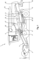
- FIG. 1 to 4 An example of implementation that is shown in the Figures 1 to 4 shown comprises a combine harvester 1 according to the invention.
- This comprises a cutting element 2, by means of which plants 3 standing in a field can be cut off.
- the cut plants 3 are then conveyed by means of an inclined conveyor 4 towards a threshing element 5 , by means of which the plants 3 are processed.
- fruits are separated from plant residues, with a significant proportion of the fruits already being separated by a threshing concave 7 of the threshing element 5.
- These fruits reach a preparation floor 6, by means of which they are conveyed further towards a downstream sieving element 9.
- the plant residues and detached fruits are furthermore conveyed from the threshing element 5 to a separating element 8 , which in the example shown is formed by a tray shaker.
- a separating device 8 By means of the separating device 8 , at least coarse plant residues are separated and fed to a chopping device 29 at a rear end of the combine harvester 1 , by means of which the plant residues are chopped.
- the plant residues are then discharged from the combine harvester 1 by means of a discharge device 30 .
- the screening element 9 comprises an upper sieve 25 and a lower sieve 26, which together are responsible for screening out the fine plant residues so that the fruit can be collected at least substantially free of plant residues.
- a suction fan 10 is arranged at a rear end of the screening element 9 , by means of which an air volume flow 11 can be sucked in at a suction side 12 of the suction fan 10. This air volume flow 11 is sucked in through several air inlet cross-sections which are formed in front of the screening element 9 as viewed in the longitudinal direction of the combine harvester 1 .
- an air inlet cross-section 13 is formed at a front end of the preparation floor 6 , wherein the air inlet cross-section 13 is located in height between the inclined conveyor 4 and the preparation floor 6 or between the threshing device 5 and the preparation floor 6.
- the air volume flow 11, which is sucked in through the air inlet cross-section 13 thus flows both along the preparation floor 6 and along the sieve device 9 and thereby continuously effects a cleaning, whereby the fine plant residues that have not yet been separated by the separating device 8 are mobilized and transported towards the suction fan 10. There they are sucked into the suction fan 10 and on a pressure side of the Suction fan 10.
- the fine plant residues can be fed to the discharge element 30 , by means of which they are finally discharged from the combine harvester 1.
- the crops are finally fed to a grain tank 28 by means of an elevator 27 and collected there until they are transferred to a transport vehicle (not shown in the figures) by means of a transfer device 33 .
- the combine harvester 1 further comprises a stone trap 22 arranged between a rear end of the elevator 4 facing the threshing unit 5 and a front end of the threshing unit 5. Height-wise, the stone trap 22 is arranged between the rear end of the elevator 4 and the preparation floor 6. The stone trap 22 serves to separate stones inadvertently carried along by the elevator 4 , preventing them from entering the threshing unit 5 .
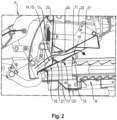
- the combine harvester 1 comprises an air inlet structure 14, which is particularly well suited to the Figures 2 to 4
- This air inlet structure 14 is arranged in the example shown between the stone trap trough 22 and the preparation floor 6.
- the preparation floor 6 is designed such that it extends to a front wall 23 of the stone trap trough 22.
- the preparation floor 6 and the stone trap trough 22 are at least substantially flush with one another along a vertical plane.
- the air inlet structure 14 is located in a space between the stone trap trough 22 and the preparation floor 6.
- the air inlet structure 14 comprises a trickle grain guard 15, which prevents the unintentional escape of fruit at the front end of a region of the preparation floor 6.
- the air inlet cross-section 13 is left open, so that the air volume flow 11 can be sucked in at the front end of the preparation floor 6 by the suction fan 10 and then flows along the preparation floor 6.
- the trickle grain guard 15 comprises a guide plate 16, which extends at an incline, viewed in the longitudinal direction of the combine harvester 1 , between the stone trap trough 22 and the preparation floor 6. The guide plate 16 is inclined such that it rises towards the rear end of the combine harvester 1 .
- the guide plate 16 has the particular function of guiding fruits which fall from the threshing concave 7 onto the preparation floor 6 and which, starting from the preparation floor 6, unfavorable manner, i.e., in an unfavorable trajectory, whereby the fruits bounce against an underside 19 of the guide plate 16 in an upward movement from the preparation floor 6 and fall back onto the preparation floor 6.
- An opening 31 is formed so that the air volume flow 11 can enter the area of the preparation floor 6 despite the guide plate 16. In principle, this opening 31 is also open to fruits in order to travel from the preparation floor 6 through the opening 31 to an upper side 18 of the guide plate 16.
- the trickle grain guard 15 comprises a catching wall 21 that extends upwardly from the top side 18 of the guide plate 16. This catching wall 21 catches the fruit.
- a plurality of openings 17 are formed in the guide plate 16 in the example shown, which openings are arranged in spatial proximity to the catching wall 21. These openings 17 serve to ensure that the fruit located on the top side 18 of the guide plate 16 can pass through the openings 17 to the bottom side 19 and thus to the preparation floor 6 .
- the air inlet structure 14 is arranged in the example shown such that the front wall 23 of the stone trap trough 22 and the trap wall 21 of the trickle grain guard 15 together delimit the air inlet cross-section 13.
- the wall 23 and the catch wall 21 are aligned at least substantially along a common plane.
- the air inlet cross-section 13 extends in the form of a slot between these two components.
- the stone trap trough 22 comprises a trickle opening 24 formed at a lowest point of the stone trap trough 22.
- Fruit that has entered the stone trap trough 22 can be drained downward through this trickle opening 24 , falling onto the air inlet structure 14.
- the trickle grain guard 15 is arranged such that the catching wall 21 is located in front of the trickle opening 24 , viewed in the longitudinal direction of the combine harvester, so that the fruit separated through the trickle opening 24 and striking the upper side 18 of the guide plate 16 are prevented from escaping the combine harvester 1 through the air inlet cross-section 13. Instead, they are intercepted by the catching wall 21 and guided through the openings 17 to the preparation floor 6 .
- the trickle grain protection 15 also comprises a baffle plate 20, which is assigned to the openings 17 from the underside 19 of the guide plate 16.
- the baffle plate 20 is oriented obliquely with respect to a plane in which the guide plate 16 extends and is designed to shield the openings 17.
- the baffle plate 20 prevents an unintentional passage of fruit from the underside 19 through the openings 17 to the upper side 18 of the guide plate 16.
- the baffle plate 20 is particularly well-defined based on Figure 4 .
Landscapes
- Life Sciences & Earth Sciences (AREA)
- Environmental Sciences (AREA)
- Threshing Machine Elements (AREA)
Claims (14)
- Moissonneuse-batteuse automotrice (1), comprenant- un organe de coupe (2) destiné à couper des plantes (3),- un convoyeur incliné (4) destiné à transporter des plantes (3) coupées, depuis l'organe de coupe (2) jusqu'à un organe de battage (5),- un organe de battage (5) destiné à détacher les fruits des plantes (3) des résidus des plantes,- une table de préparation (6) qui est disposée sous l'organe de battage (5) et permet de recueillir les fruits séparés par un contre-batteur (7) de l'organe de battage (5),- un organe de séparation (8) destiné à séparer les fruits détachés des résidus de plantes grossiers,- un organe formant grille (9) destiné à séparer les fruits détachés des résidus de plantes fins,- un ventilateur aspirant à vent (10) destiné à générer un flux volumique d'air (11) permettant de nettoyer en continu l'organe formant grille (9),dans laquelle le ventilateur aspirant à vent (10) est disposé après l'organe formant grille (9), vu dans le sens longitudinal de la moissonneuse-batteuse (1), et présente un côté aspiration (12) associé à l'organe formant grille (9), sur lequel le flux volumique d'air (11) peut être aspiré,dans laquelle, vu dans le sens longitudinal de la moissonneuse-batteuse (1), au moins une section d'admission d'air (13) est réalisée avant l'organe formant grille (9), à travers laquelle le flux volumique d'air (11) peut être aspiré,dans laquelle la section d'admission d'air (13) est réalisée sur une structure d'admission d'air (14),dans laquelle la structure d'admission d'air (14) présente une protection contre le ruissellement de grains (15) qui réduit la sortie non souhaitée de fruits à travers la section d'admission d'air (13),caractérisée en ce que la structure d'admission d'air (14) est disposée entre l'organe de battage (5) et la table de préparation (6).
- Moissonneuse-batteuse (1) selon la revendication 1, caractérisée en ce que la protection contre le ruissellement de grains (15) est réalisée à la manière d'un joint labyrinthe, de sorte que la protection contre le ruissellement de grains (15) impose une déviation multiple du flux volumique d'air (11), lors de l'entrée de celui-ci.
- Moissonneuse-batteuse (1) selon une des revendications précédentes, caractérisée en ce que la protection contre le ruissellement de grains (15) comprend une tôle de guidage (16) qui s'étend entre l'organe de battage (5) et la table de préparation (6).
- Moissonneuse-batteuse (1) selon la revendication 3, caractérisée en ce que dans la tôle de guidage (16), il est prévu au moins une ouverture (17) à travers laquelle des fruits peuvent tomber depuis une face supérieure (18) de la tôle de guidage (16) en direction de la table de préparation (6).
- Moissonneuse-batteuse (1) selon la revendication 4, caractérisée en ce que la protection contre le ruissellement de grains (15) comprend, sur une face inférieure (19) de la tôle de guidage (16), une tôle déflectrice (20) qui est associée à l'ouverture (17) et permet de protéger l'ouverture (17) de manière à éviter le passage non intentionnel de fruits depuis la face inférieure (19) de la tôle de guidage (16), à travers l'ouverture (17), vers la face supérieure (18) de la tôle de guidage (16).
- Moissonneuse-batteuse (1) selon la revendication 4 ou 5, caractérisée en ce que, vu dans le sens d'écoulement du flux volumique d'air (11), la protection contre le ruissellement de grains (15) comprend une paroi d'arrêt (21) qui est située avant l'ouverture (17), au nombre d'au moins une, et dépasse vers le haut par rapport à la face supérieure (18) de la tôle de guidage (16).
- Moissonneuse-batteuse (1) selon une des revendications 3 à 6, caractérisée en ce que, vu dans le sens longitudinal de la moissonneuse-batteuse (1), la tôle de guidage (16) est orientée avec une pente ascendante.
- Moissonneuse-batteuse (1) selon une des revendications précédentes, caractérisée en ce qu'elle comporte un bac à pierres (22) qui est disposé à une extrémité de l'organe de battage (5) tournée vers le convoyeur incliné (4) et est agencé pour séparer des pierres indésirables avant leur entrée dans l'organe de battage (5).
- Moissonneuse-batteuse (1) selon la revendication 8, caractérisée en ce que la table de préparation (6) s'étend sous le bac à pierres (22), jusqu'à une extrémité du bac à pierres (22) tournée vers le convoyeur incliné (4).
- Moissonneuse-batteuse (1) selon la revendication 8 ou 9, caractérisée en ce que la structure d'admission d'air (14) est disposée sous une extrémité du bac à pierres (22) tournée vers le convoyeur incliné (4).
- Moissonneuse-batteuse (1) selon les revendications 6 et 10, caractérisée en ce que la paroi d'arrêt (21) de la protection contre le ruissellement de grains (15) et une paroi avant (23) du bac à pierres (22) délimitent ensemble la section d'admission d'air (13), la paroi d'arrêt (21) de la protection contre le ruissellement de grains (15) et la paroi (23) du bac à pierres (22) s'étendant de préférence dans un plan commun.
- Moissonneuse-batteuse (1) selon la revendication 10 ou 11, caractérisée en ce que le bac à pierres (22) présente une ouverture de ruissellement (24) à travers laquelle des fruits qui sont arrivés dans le bac à pierres (22) peuvent être évacués en direction de la structure d'admission d'air (14).
- Moissonneuse-batteuse (1) selon les revendications 6 et 12, caractérisée en ce que, vu dans la direction longitudinale de la moissonneuse-batteuse (1), la paroi d'arrêt (21) de la protection contre le ruissellement de grains (15) est disposée avant l'ouverture de ruissellement (24), de sorte que des fruits qui tombent sur la protection contre le ruissellement de grains (15) à travers l'ouverture de ruissellement (24) sont empêchés par la paroi d'arrêt (21) de sortir de la moissonneuse-batteuse (1) en direction d'un côté avant de celle-ci.
- Moissonneuse-batteuse (1) selon la revendication 13, caractérisée en ce que l'ouverture (17) de la tôle de guidage (16) est associée dans l'espace à l'ouverture de ruissellement (24), de manière à ce que des fruits tombant à travers l'ouverture de ruissellement (24) peuvent être dirigés à travers la protection contre le ruissellement de grains
Applications Claiming Priority (1)
| Application Number | Priority Date | Filing Date | Title |
|---|---|---|---|
| DE102022109874.5A DE102022109874A1 (de) | 2022-04-25 | 2022-04-25 | Selbstfahrender Mähdrescher |
Publications (2)
| Publication Number | Publication Date |
|---|---|
| EP4268570A1 EP4268570A1 (fr) | 2023-11-01 |
| EP4268570B1 true EP4268570B1 (fr) | 2025-04-09 |
Family
ID=85221864
Family Applications (1)
| Application Number | Title | Priority Date | Filing Date |
|---|---|---|---|
| EP23155731.5A Active EP4268570B1 (fr) | 2022-04-25 | 2023-02-09 | Moissonneuse-batteuse automotrice |
Country Status (2)
| Country | Link |
|---|---|
| EP (1) | EP4268570B1 (fr) |
| DE (1) | DE102022109874A1 (fr) |
Families Citing this family (1)
| Publication number | Priority date | Publication date | Assignee | Title |
|---|---|---|---|---|
| DE102024127440A1 (de) | 2024-09-23 | 2026-03-26 | Claas Selbstfahrende Erntemaschinen Gmbh | Selbstfahrender Mähdrescher |
Family Cites Families (5)
| Publication number | Priority date | Publication date | Assignee | Title |
|---|---|---|---|---|
| DE2419141A1 (de) | 1974-04-20 | 1975-10-30 | Claas Maschf Gmbh Geb | Steinfangmulde fuer maehdrescher |
| DE2620875A1 (de) * | 1976-05-11 | 1977-11-24 | Brugger Josef | Kornreinigungsvorrichtung fuer maehdrescher |
| DE102005056115A1 (de) * | 2005-11-23 | 2007-05-24 | Claas Selbstfahrende Erntemaschinen Gmbh | Mähdrescher mit Sauggebläse |
| DE102018131432A1 (de) * | 2018-12-07 | 2020-06-10 | Claas Selbstfahrende Erntemaschinen Gmbh | Selbstfahrender Mähdrescher |
| DE102020111603A1 (de) * | 2020-04-29 | 2021-11-04 | Claas Selbstfahrende Erntemaschinen Gmbh | Selbstfahrender Mähdrescher sowie Verfahren zur Ernte |
-
2022
- 2022-04-25 DE DE102022109874.5A patent/DE102022109874A1/de active Pending
-
2023
- 2023-02-09 EP EP23155731.5A patent/EP4268570B1/fr active Active
Also Published As
| Publication number | Publication date |
|---|---|
| DE102022109874A1 (de) | 2023-10-26 |
| EP4268570A1 (fr) | 2023-11-01 |
Similar Documents
| Publication | Publication Date | Title |
|---|---|---|
| DE69512733T2 (de) | Reinigungsvorrichtung für Erntemaschine | |
| DE102018131432A1 (de) | Selbstfahrender Mähdrescher | |
| EP1389416A2 (fr) | Dispositif de nettoyage et dispositif soufflant de nettoyage pour une moissonneuse-batteuse | |
| EP1897430B1 (fr) | Dispositif de hachage et de répartition | |
| EP3753393B1 (fr) | Moissonneuse-batteuse automotrice | |
| EP3520596B1 (fr) | Moissonneuse-batteuse | |
| DE102005056115A1 (de) | Mähdrescher mit Sauggebläse | |
| DE212014000207U1 (de) | Kornreinigungseinrichtung eines Mähdreschers | |
| EP3662737A1 (fr) | Moissonneuse-batteuse automotrice | |
| EP4268570B1 (fr) | Moissonneuse-batteuse automotrice | |
| DE102007062531A1 (de) | Mähdrescher mit Reinigungsgebläse | |
| EP0727135A1 (fr) | Moissonneuse-batteuse | |
| EP3903557B1 (fr) | Moissonneuse-batteuse autonome, ainsi que procédé de récolte | |
| DE19624733A1 (de) | Mähdrescher | |
| EP0503408A1 (fr) | Machine de récolte, notamment moissonneuse-batteuse, avec une soufflerie et une unité de traitement au moins partiellement entourée d'un châssis | |
| EP3613276B1 (fr) | Automotrice de récolte, en particulier moissonneuse-batteuse | |
| EP1378161B1 (fr) | Dispositif pneumatique de tamisage | |
| DD276616A1 (de) | Reinigungseinrichtung fuer maehdrescher | |
| EP0683970A2 (fr) | Dispositif soufflant de nettoyage pour batteuse | |
| EP3150058B1 (fr) | Moissonneuse-batteuse | |
| DE4209503C2 (de) | Vorrichtung für selbstfahrende Mähdrescher | |
| DE69222414T2 (de) | Überkehr-Rückführungseinrichtung für Mähdrescher | |
| DE1121873B (de) | Reinigungseinrichtung in Dreschmaschinen, insbesondere in Maehdreschern | |
| DE102024127444A1 (de) | Selbstfahrender Mähdrescher | |
| DE102024127440A1 (de) | Selbstfahrender Mähdrescher |
Legal Events
| Date | Code | Title | Description |
|---|---|---|---|
| PUAI | Public reference made under article 153(3) epc to a published international application that has entered the european phase |
Free format text: ORIGINAL CODE: 0009012 |
|
| STAA | Information on the status of an ep patent application or granted ep patent |
Free format text: STATUS: THE APPLICATION HAS BEEN PUBLISHED |
|
| AK | Designated contracting states |
Kind code of ref document: A1 Designated state(s): AL AT BE BG CH CY CZ DE DK EE ES FI FR GB GR HR HU IE IS IT LI LT LU LV MC ME MK MT NL NO PL PT RO RS SE SI SK SM TR |
|
| P01 | Opt-out of the competence of the unified patent court (upc) registered |
Effective date: 20231102 |
|
| STAA | Information on the status of an ep patent application or granted ep patent |
Free format text: STATUS: REQUEST FOR EXAMINATION WAS MADE |
|
| 17P | Request for examination filed |
Effective date: 20240502 |
|
| RBV | Designated contracting states (corrected) |
Designated state(s): AL AT BE BG CH CY CZ DE DK EE ES FI FR GB GR HR HU IE IS IT LI LT LU LV MC ME MK MT NL NO PL PT RO RS SE SI SK SM TR |
|
| GRAP | Despatch of communication of intention to grant a patent |
Free format text: ORIGINAL CODE: EPIDOSNIGR1 |
|
| STAA | Information on the status of an ep patent application or granted ep patent |
Free format text: STATUS: GRANT OF PATENT IS INTENDED |
|
| RIC1 | Information provided on ipc code assigned before grant |
Ipc: A01F 12/48 20060101AFI20241010BHEP |
|
| INTG | Intention to grant announced |
Effective date: 20241021 |
|
| GRAS | Grant fee paid |
Free format text: ORIGINAL CODE: EPIDOSNIGR3 |
|
| GRAA | (expected) grant |
Free format text: ORIGINAL CODE: 0009210 |
|
| STAA | Information on the status of an ep patent application or granted ep patent |
Free format text: STATUS: THE PATENT HAS BEEN GRANTED |
|
| AK | Designated contracting states |
Kind code of ref document: B1 Designated state(s): AL AT BE BG CH CY CZ DE DK EE ES FI FR GB GR HR HU IE IS IT LI LT LU LV MC ME MK MT NL NO PL PT RO RS SE SI SK SM TR |
|
| REG | Reference to a national code |
Ref country code: GB Ref legal event code: FG4D Free format text: NOT ENGLISH |
|
| REG | Reference to a national code |
Ref country code: CH Ref legal event code: EP |
|
| REG | Reference to a national code |
Ref country code: DE Ref legal event code: R096 Ref document number: 502023000790 Country of ref document: DE |
|
| REG | Reference to a national code |
Ref country code: IE Ref legal event code: FG4D Free format text: LANGUAGE OF EP DOCUMENT: GERMAN |
|
| REG | Reference to a national code |
Ref country code: NL Ref legal event code: MP Effective date: 20250409 |
|
| PG25 | Lapsed in a contracting state [announced via postgrant information from national office to epo] |
Ref country code: NL Free format text: LAPSE BECAUSE OF FAILURE TO SUBMIT A TRANSLATION OF THE DESCRIPTION OR TO PAY THE FEE WITHIN THE PRESCRIBED TIME-LIMIT Effective date: 20250409 |
|
| PG25 | Lapsed in a contracting state [announced via postgrant information from national office to epo] |
Ref country code: FI Free format text: LAPSE BECAUSE OF FAILURE TO SUBMIT A TRANSLATION OF THE DESCRIPTION OR TO PAY THE FEE WITHIN THE PRESCRIBED TIME-LIMIT Effective date: 20250409 Ref country code: ES Free format text: LAPSE BECAUSE OF FAILURE TO SUBMIT A TRANSLATION OF THE DESCRIPTION OR TO PAY THE FEE WITHIN THE PRESCRIBED TIME-LIMIT Effective date: 20250409 Ref country code: PT Free format text: LAPSE BECAUSE OF FAILURE TO SUBMIT A TRANSLATION OF THE DESCRIPTION OR TO PAY THE FEE WITHIN THE PRESCRIBED TIME-LIMIT Effective date: 20250811 |
|
| REG | Reference to a national code |
Ref country code: LT Ref legal event code: MG9D |
|
| PG25 | Lapsed in a contracting state [announced via postgrant information from national office to epo] |
Ref country code: GR Free format text: LAPSE BECAUSE OF FAILURE TO SUBMIT A TRANSLATION OF THE DESCRIPTION OR TO PAY THE FEE WITHIN THE PRESCRIBED TIME-LIMIT Effective date: 20250710 Ref country code: NO Free format text: LAPSE BECAUSE OF FAILURE TO SUBMIT A TRANSLATION OF THE DESCRIPTION OR TO PAY THE FEE WITHIN THE PRESCRIBED TIME-LIMIT Effective date: 20250709 |
|
| PG25 | Lapsed in a contracting state [announced via postgrant information from national office to epo] |
Ref country code: PL Free format text: LAPSE BECAUSE OF FAILURE TO SUBMIT A TRANSLATION OF THE DESCRIPTION OR TO PAY THE FEE WITHIN THE PRESCRIBED TIME-LIMIT Effective date: 20250409 |
|
| PG25 | Lapsed in a contracting state [announced via postgrant information from national office to epo] |
Ref country code: BG Free format text: LAPSE BECAUSE OF FAILURE TO SUBMIT A TRANSLATION OF THE DESCRIPTION OR TO PAY THE FEE WITHIN THE PRESCRIBED TIME-LIMIT Effective date: 20250409 |
|
| PG25 | Lapsed in a contracting state [announced via postgrant information from national office to epo] |
Ref country code: HR Free format text: LAPSE BECAUSE OF FAILURE TO SUBMIT A TRANSLATION OF THE DESCRIPTION OR TO PAY THE FEE WITHIN THE PRESCRIBED TIME-LIMIT Effective date: 20250409 |
|
| PG25 | Lapsed in a contracting state [announced via postgrant information from national office to epo] |
Ref country code: RS Free format text: LAPSE BECAUSE OF FAILURE TO SUBMIT A TRANSLATION OF THE DESCRIPTION OR TO PAY THE FEE WITHIN THE PRESCRIBED TIME-LIMIT Effective date: 20250709 |
|
| PG25 | Lapsed in a contracting state [announced via postgrant information from national office to epo] |
Ref country code: IS Free format text: LAPSE BECAUSE OF FAILURE TO SUBMIT A TRANSLATION OF THE DESCRIPTION OR TO PAY THE FEE WITHIN THE PRESCRIBED TIME-LIMIT Effective date: 20250809 |
|
| PG25 | Lapsed in a contracting state [announced via postgrant information from national office to epo] |
Ref country code: LV Free format text: LAPSE BECAUSE OF FAILURE TO SUBMIT A TRANSLATION OF THE DESCRIPTION OR TO PAY THE FEE WITHIN THE PRESCRIBED TIME-LIMIT Effective date: 20250409 |
|
| REG | Reference to a national code |
Ref country code: DE Ref legal event code: R097 Ref document number: 502023000790 Country of ref document: DE |
|
| PG25 | Lapsed in a contracting state [announced via postgrant information from national office to epo] |
Ref country code: DK Free format text: LAPSE BECAUSE OF FAILURE TO SUBMIT A TRANSLATION OF THE DESCRIPTION OR TO PAY THE FEE WITHIN THE PRESCRIBED TIME-LIMIT Effective date: 20250409 Ref country code: SM Free format text: LAPSE BECAUSE OF FAILURE TO SUBMIT A TRANSLATION OF THE DESCRIPTION OR TO PAY THE FEE WITHIN THE PRESCRIBED TIME-LIMIT Effective date: 20250409 |
|
| PG25 | Lapsed in a contracting state [announced via postgrant information from national office to epo] |
Ref country code: CZ Free format text: LAPSE BECAUSE OF FAILURE TO SUBMIT A TRANSLATION OF THE DESCRIPTION OR TO PAY THE FEE WITHIN THE PRESCRIBED TIME-LIMIT Effective date: 20250409 |
|
| PG25 | Lapsed in a contracting state [announced via postgrant information from national office to epo] |
Ref country code: EE Free format text: LAPSE BECAUSE OF FAILURE TO SUBMIT A TRANSLATION OF THE DESCRIPTION OR TO PAY THE FEE WITHIN THE PRESCRIBED TIME-LIMIT Effective date: 20250409 |
|
| PG25 | Lapsed in a contracting state [announced via postgrant information from national office to epo] |
Ref country code: SK Free format text: LAPSE BECAUSE OF FAILURE TO SUBMIT A TRANSLATION OF THE DESCRIPTION OR TO PAY THE FEE WITHIN THE PRESCRIBED TIME-LIMIT Effective date: 20250409 |
|
| PG25 | Lapsed in a contracting state [announced via postgrant information from national office to epo] |
Ref country code: IT Free format text: LAPSE BECAUSE OF FAILURE TO SUBMIT A TRANSLATION OF THE DESCRIPTION OR TO PAY THE FEE WITHIN THE PRESCRIBED TIME-LIMIT Effective date: 20250409 |
|
| PLBE | No opposition filed within time limit |
Free format text: ORIGINAL CODE: 0009261 |
|
| STAA | Information on the status of an ep patent application or granted ep patent |
Free format text: STATUS: NO OPPOSITION FILED WITHIN TIME LIMIT |
|
| REG | Reference to a national code |
Ref country code: CH Ref legal event code: L10 Free format text: ST27 STATUS EVENT CODE: U-0-0-L10-L00 (AS PROVIDED BY THE NATIONAL OFFICE) Effective date: 20260218 |
|
| 26N | No opposition filed |
Effective date: 20260112 |
|
| PGFP | Annual fee paid to national office [announced via postgrant information from national office to epo] |
Ref country code: DE Payment date: 20260218 Year of fee payment: 4 |
|
| PGFP | Annual fee paid to national office [announced via postgrant information from national office to epo] |
Ref country code: AT Payment date: 20260301 Year of fee payment: 4 |