EP4269732A1 - Griffvorrichtung für ein fahrzeug - Google Patents
Griffvorrichtung für ein fahrzeug Download PDFInfo
- Publication number
- EP4269732A1 EP4269732A1 EP21910450.2A EP21910450A EP4269732A1 EP 4269732 A1 EP4269732 A1 EP 4269732A1 EP 21910450 A EP21910450 A EP 21910450A EP 4269732 A1 EP4269732 A1 EP 4269732A1
- Authority
- EP
- European Patent Office
- Prior art keywords
- adjuster
- main body
- handle
- handle main
- head portion
- Prior art date
- Legal status (The legal status is an assumption and is not a legal conclusion. Google has not performed a legal analysis and makes no representation as to the accuracy of the status listed.)
- Pending
Links
Images




Classifications
-
- E—FIXED CONSTRUCTIONS
- E05—LOCKS; KEYS; WINDOW OR DOOR FITTINGS; SAFES
- E05B—LOCKS; ACCESSORIES THEREFOR; HANDCUFFS
- E05B85/00—Details of vehicle locks not provided for in groups E05B77/00 - E05B83/00
- E05B85/10—Handles
- E05B85/107—Pop-out handles, e.g. sliding outwardly before rotation
-
- E—FIXED CONSTRUCTIONS
- E05—LOCKS; KEYS; WINDOW OR DOOR FITTINGS; SAFES
- E05B—LOCKS; ACCESSORIES THEREFOR; HANDCUFFS
- E05B79/00—Mounting or connecting vehicle locks or parts thereof
- E05B79/02—Mounting of vehicle locks or parts thereof
- E05B79/06—Mounting of handles, e.g. to the wing or to the lock
-
- E—FIXED CONSTRUCTIONS
- E05—LOCKS; KEYS; WINDOW OR DOOR FITTINGS; SAFES
- E05B—LOCKS; ACCESSORIES THEREFOR; HANDCUFFS
- E05B81/00—Power-actuated vehicle locks
- E05B81/24—Power-actuated vehicle locks characterised by constructional features of the actuator or the power transmission
- E05B81/32—Details of the actuator transmission
- E05B81/42—Cams
-
- E—FIXED CONSTRUCTIONS
- E05—LOCKS; KEYS; WINDOW OR DOOR FITTINGS; SAFES
- E05B—LOCKS; ACCESSORIES THEREFOR; HANDCUFFS
- E05B85/00—Details of vehicle locks not provided for in groups E05B77/00 - E05B83/00
- E05B85/10—Handles
- E05B85/103—Handles creating a completely closed wing surface
-
- E—FIXED CONSTRUCTIONS
- E05—LOCKS; KEYS; WINDOW OR DOOR FITTINGS; SAFES
- E05B—LOCKS; ACCESSORIES THEREFOR; HANDCUFFS
- E05B63/00—Locks or fastenings with special structural characteristics
- E05B63/0056—Locks with adjustable or exchangeable lock parts
-
- E—FIXED CONSTRUCTIONS
- E05—LOCKS; KEYS; WINDOW OR DOOR FITTINGS; SAFES
- E05B—LOCKS; ACCESSORIES THEREFOR; HANDCUFFS
- E05B77/00—Vehicle locks characterised by special functions or purposes
- E05B77/36—Noise prevention; Anti-rattling means
- E05B77/38—Cushion elements, elastic guiding elements or holding elements, e.g. for cushioning or damping the impact of the bolt against the striker during closing of the wing
-
- E—FIXED CONSTRUCTIONS
- E05—LOCKS; KEYS; WINDOW OR DOOR FITTINGS; SAFES
- E05B—LOCKS; ACCESSORIES THEREFOR; HANDCUFFS
- E05B81/00—Power-actuated vehicle locks
- E05B81/02—Power-actuated vehicle locks characterised by the type of actuators used
- E05B81/04—Electrical
- E05B81/06—Electrical using rotary motors
-
- E—FIXED CONSTRUCTIONS
- E05—LOCKS; KEYS; WINDOW OR DOOR FITTINGS; SAFES
- E05B—LOCKS; ACCESSORIES THEREFOR; HANDCUFFS
- E05B85/00—Details of vehicle locks not provided for in groups E05B77/00 - E05B83/00
- E05B85/10—Handles
- E05B85/14—Handles pivoted about an axis parallel to the wing
- E05B85/16—Handles pivoted about an axis parallel to the wing a longitudinal grip part being pivoted at one end about an axis perpendicular to the longitudinal axis of the grip part
Definitions
- the present disclosure relates to a handle device for a vehicle.
- Patent Literature 1 discloses a handle device including a handle main body that can be pulled out from an initial position during a door operation.
- the handle device includes a handle portion (handle main body) rotatably connected to one end of an operation lever driven by an electric motor (electric actuator) fixed on a handle base, and a lock release lever connected to an end opposite to a connection end of the handle main body to the operation lever, and one end of the handle main body and a guide portion formed on one end of the lock release lever are slidably fitted to a guide with a slit formed on the handle base.
- the handle main body moves from an initial position where the handle main body is positioned on the same surface as a door panel to an operation position where the handle main body is lifted from the door panel, and when the handle main body is operated at the operation position, a release operation of a door latch device can be performed.
- Patent Literature 1 JP2016-537532A
- the initial position is uniquely determined by a dimensional relationship between components, and when there is a dimension error or the like, there is a possibility that the handle main body is not held on the same surface as the door panel.
- the present disclosure relates to a handle device for a vehicle in which a positional relationship between a handle main body and a surface of a door panel can be adjusted to a predetermined position even if there is an error between components.
- a handle device for a vehicle includes a handle base fixed to a vehicle, and a handle main body connected to the handle base and configured to be able to be pulled out from an initial position.
- the handle base is provided with an adjustment portion.
- the adjustment portion is configured to be operable by being exposed to outside when the handle main body is pulled out from the initial position, and to adjust a position of the handle main body at the initial position.
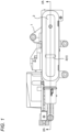
- the door handle device includes a handle base 1, a handle main body 2, and first and second links 12, 13 that connect the handle main body 2 to the handle base 1.
- the handle base 1 is fixed to a door of the vehicle.
- a hand hold portion 2a which is held when a door is operated, is formed in a central portion of the handle main body 2 in a longitudinal direction.
- the handle main body 2 is configured to be movable between an initial position, a pop-up position, and a latch operation position to be described below.
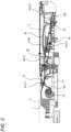
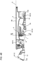
- a surface 2b of the handle main body 2 becomes substantially the same surface as a door panel (a door surface 5) as shown in Figs. 2 and 3A , and the hand hold portion 2a is accommodated in the door.
- the handle main body 2 is positioned at the pop-up position ( Fig.
- the hand hold portion 2a pops out of the door panel, and the handle main body 2 can be operated by putting a hand over the hand hold portion 2a.
- the handle main body 2 is positioned at the latch operation position, as shown in Fig. 3C , the handle main body 2 is in a state in which one end of the handle main body 2 is pulled up from the pop-up position.
- a driven portion 12a of the first link 12 is pressed against a cam member 14 that is rotationally driven by a motor (not shown), and the first link 12 is driven to rotate about a connecting shaft A112 to the handle base 1.
- a clockwise rotational moment M12 is applied to the first link 12 by a torsion spring 15.
- An end of the first link 12 opposite to a connecting end of the first link 12 to the handle base 1 is rotatably connected to one end of the handle main body 2 about a connecting shaft A212.
- one end of the second link 13 is rotatably connected to the handle base 1 about a connecting shaft A113.
- a long hole 13a is formed at an opposite end of the second link 13, and a connecting shaft A213 fixed to the other end of the handle main body 2 is rotatably and slidably inserted.
- component members of the handle device constitute a 5-node link mechanism having the handle base 1 as a fixed link, the first and second links 12, 13 connected to the fixed link by revolute pairs at intervals between the connecting shafts A112, A113, the slider long hole 13a connected to the second link 13 by a sliding pair, and the handle main body 2 having both ends connected to the first link 12 and the slider 13a in a revolute pair, as elements.
- a sliding stroke end of the slider 13a sliding on the second link 13 is determined in advance as an end position of the long hole 13a, and in addition to the rotational moment M12 applied to the first link 12 described above, a clockwise rotational moment M113 in Fig. 3A is applied to the second link 13 by a torsion spring 16, whereby the slider 13a is held at a stroke end position on the connecting shaft A113 side of the second link 13 to the handle base 1.
- link lengths of the fixed link and the handle main body 2 are equal to each other, and a distance (distance between the connecting shafts A113 and A213 in Fig. 3A ) between the slider 13a at the stoke end position and the connecting shaft A 113 of the fixed link of the second link 13 is equal to a link length of the first link 12, when an electric rotation operation is performed using the first link 12 as a drive link, the handle device substantially operates as a parallel link of four nodes.
- the handle base 1 is provided with a latch operation mechanism (not shown) which operates by the rotation of the connecting shaft A113 of the second link 13 with the handle base 1 from Fig. 3B to Fig. 3C , and the latch operation mechanism releases a door latch device fixed to the door through an appropriate transmission means such as a cable device in accordance with the rotation of the handle main body 2 to an operation position.
- a latch operation mechanism (not shown) which operates by the rotation of the connecting shaft A113 of the second link 13 with the handle base 1 from Fig. 3B to Fig. 3C , and the latch operation mechanism releases a door latch device fixed to the door through an appropriate transmission means such as a cable device in accordance with the rotation of the handle main body 2 to an operation position.
- the handle base 1 is provided with an adjustment portion 3.
- the adjustment portion 3 includes a holding portion 7 and an adjuster 4 rotatably held by the holding portion 7.
- the holding portion 7 has a widthwise dimension substantially equal to a widthwise dimension of the hand hold portion 2a of the handle main body 2, and includes a columnar head portion 8 and a connecting portion 9 protruding from a peripheral wall of the columnar head portion 8.
- a stopper wall 9a projects from a protruding base end of the connecting portion 9 from the columnar head portion 8, and an elastic leg 9b projects from an end of the stopper wall 9a.
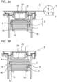
- the elastic leg 9b projects from both end portions of the stopper wall 9a in the width direction, and the holding portion 7 is fixed to the handle base 1 by elastically locking a locking claw 9c formed at a tip end of the elastic leg 9b to a locking opening 1a formed in the handle base 1, as shown in Figs. 5A and 5B .
- the holding portion 7 is fixed in a posture in which the connecting portion 9 extends from the columnar head portion 8 toward a center in a vehicle width direction or extends along a thickness direction of the door, and the columnar head portion 8 is positioned at the outermost side in the vehicle width direction.
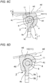
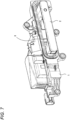
- the adjuster 4 is formed of a material having good impact absorption capacity, such as rubber, a flexible synthetic resin material, or the like. As shown in Fig. 6B , the adjuster 4 is formed by projecting an attachment piece 4b extending from both side walls of a link receiving portion 4a along a side wall portion of the holding portion 7, and an attachment shaft 6 fixed on a center axis of the columnar head portion 8 is inserted into the attachment piece 4b and is connected to the holding portion 7.
- a back surface (inner peripheral surface) of the link receiving portion 4a of the adjuster 4 is in contact with and supported by a surface of the columnar head portion 8 of the holding portion 7, the link receiving portion 4a covers the surface of the columnar head portion 8, and the back surface of the link receiving portion 4a can rotate about the attachment shaft 6 while sliding on the surface of the columnar head portion 8.
- stoppers 4c that abut against the stopper wall 9a of the holding portion 7 to restrict a rotation angle are formed in the adjuster 4.
- a convex portion 10 for click having a protruding shape on the back surface of the link receiving portion 4a of the adjuster 4 is formed over the entire length in the width direction of the adjuster 4, and concave portions 11 for click having a groove shape on the peripheral wall of the columnar head portion 8 of the holding portion 7 are formed over the entire length in the width direction of the holding portion 7.
- a restraint stop position (rotation stop position) is set at two positions (an initial rotation position shown in Fig. 6C and an adjustment rotation position shown in Fig. 6D ) at a rotation end position where the stopper 4c abuts against the stopper wall 9a, but the restraint stop position may be added to these intermediate positions.
- An outer peripheral wall of the link receiving portion 4a has a cam shape in which a distance from the attachment shaft 6 is different depending on the rotation angle.
- the adjuster 4 is formed in a cam shape in which a distance between a rotation center (the attachment shaft 6) of the adjuster 4 and a surface of the outer peripheral wall of the adjuster 4 is different along a peripheral direction of the adjuster 4.
- two abutment surfaces 4d are formed at two positions corresponding to two restraint stop positions. Each of the abutment surfaces 4d is formed by an inclined surface configured to abut against a ridge line on the back surface of the hand hold portion 2a.
- the distance of the abutment surface 4d from the attachment shaft 6 is set such that, when the surface of the handle main body 2 is shifted from a predetermined position, for example, a position where the surface of the handle main body 2 is flush with the surface of the door panel 5 in a state in which the handle main body 2 is at the initial position, accurately when the surface of the handle main body 2 is at a position sinking from the surface of the door panel 5, the handle main body 2 can be pushed out to a predetermined position.
- the adjuster 4 also serves as a bumper at the initial position of the handle main body 2 at the time of initial setting, and the abutment surface 4d is formed so as to abut on the back surface of the hand hold portion 2a of the handle main body 2 at the time of the initial setting.
- the abutment surface 4d of the adjuster 4 is formed by the inclined surface having the same inclination angle as the inclination angle of the ridge line on the back surface of the hand hold portion 2a of the handle main body 2 with respect to a predetermined horizontal plane, and when the rotation operation is performed from the initial rotation position shown in Fig. 6C to the adjustment rotation position shown in Fig. 6D , the abutment surface 4d moves from a position indicated by a solid line to a position indicated by a chain line in Fig. 6C .
- the chain line in Fig. 6D indicates the position of the abutment surface at the initial rotation position.
- the handle main body 2 is pushed out by a distance ( ⁇ ) in the vehicle width direction, and as shown in Figs. 4B and 5B , when the handle main body 2 is positioned at the initial position, the surface of the handle main body 2 coincides with the surface of the door panel 5.
- a positional relationship between the handle main body 2 and the door panel 5 at the initial position can be adjusted by temporarily moving the handle main body 2 to the pop-up position and operating the adjuster 4 from the initial rotation position to the adjustment rotation position.
- a relative relationship between the handle main body and the door panel 5 of most of the handle devices can be kept within a range of an allowable value of the handle device for a vehicle of the embodiment of the present disclosure by a change operation of the two positions of the initial rotation position and the adjustment rotation position, but it is also possible to perform fine adjustment by further setting third and fourth rotational restraint positions and making positions of the respective abutment surfaces different.
- the handle device for a vehicle includes the handle base 1 fixed to a vehicle, and a handle main body 2 connected to the handle base 1 and configured to be able to be pulled out from the initial position.
- the handle base 1 is provided with the adjustment portion 3.
- the adjustment portion 3 is configured to be operable by being exposed to the outside when the handle main body 2 is pulled out from the initial position, and to adjust the position of the handle main body 2 at the initial position.
- the surface of the handle main body 2 needs to occupy a predetermined relative position with respect to the door surface 5 from a design demand or the like.
- the relative position of the handle main body 2 with respect to the door surface 5 at the initial position can be adjusted by operating the adjustment portion 3.
- the handle main body 2 can be adjusted to a predetermined position.
- the adjustment portion 3 Since the adjustment portion 3 is exposed to the outside in a state in which the handle main body 2 is moved from the initial position, an adjustment operation of the adjustment portion 3 is possible. Therefore, the position of the handle main body 2 can be adjusted while the handle device is fixed to the door. As a result, adjustment workability is improved.
- the adjustment portion 3 is exposed to the outside in the state in which the handle main body 2 is moved from the initial position, and is not recognized from the outside at the initial position. Therefore, an uncomfortable feeling on the design does not occur.
- the adjustment portion 3 may be configured by, for example, a screw that adjusts the position of the handle base 1 itself as long as the adjustment portion 3 can adjust the relative position of the handle main body 2 with respect to the door surface 5.
- the adjuster 4 can be included in the adjustment portion 3.
- both the handle main body 2 and the handle base 1 may together form the link mechanism having a fixed link and a plurality of movable links.
- the handle base 1 is the fixed link, and the handle main body 2 may be one of a plurality of movable links.
- the adjustment portion 3 may include the adjuster 4.
- the adjuster 4 is disposed in a moving range of the handle main body 2 or another movable link, determines a movement stroke end on an initial position side of the handle main body 2 and the like by abutting against the handle main body 2 and the like, and as a result, adjusts the initial position of the handle main body 2.
- the adjuster 4 may be configured to abut against any one of the plurality of movable links and to determine the stroke end of any one of the movable links corresponding to a position where any one of the movable links is positioned when the handle main body 2 is at the initial position.
- the adjuster 4 can be vertically rotatably operated around the attachment shaft 6 extending parallel to the door surface 5, and can be formed in a cam shape with an outer peripheral wall having a different distance from the rotation center by a rotation angle.
- the adjuster 4 may be formed in a cam shape in which the distance between the attachment shaft 6 and the surface of the outer peripheral wall of the adjuster 4 is different along the peripheral direction of the adjuster 4.
- the adjuster 4 can be stopped at an appropriate rotation position in a stepless manner by using an appropriate fastening means, but when the adjuster 4 is held by the columnar head portion 8 of the holding portion 7 connected to the handle base 1 so as to be able to be restrictively stopped at an appropriate rotation angle, the structure is simple and the adjustment operation is also simple. That is, the adjustment portion 3 may further include the holding portion 7 including the columnar head portion 8 and the connecting portion 9.
- the attachment shaft 6 may extend on the center axis of the columnar head portion 8 and protrude from the columnar head portion 9.
- the connecting portion 9 may project from the columnar head portion 8 and be connected to the handle base 1.
- the adjuster 4 may be connected to the attachment shaft 6, the inner peripheral surface of the adjuster 4 may be supported on the surface of the columnar head portion 8, and may be slidable on the surface of the columnar head portion 8.
- the convex portion 10 for click and the concave portion 11 for click may be respectively formed on the inner peripheral surface of the adjuster 4 and the surface of the columnar head portion 8, and the convex portion 10 for click and the concave portion 11 for click may be configured to be fitted to each other so that the adjuster 4 can be restrictively stopped at any rotation angle.
- the adjuster 4 When the adjuster 4 is formed of a material having an impact absorption capacity, the adjuster 4 functions as a bumper for returning the handle main body 2 to the initial position, and it is possible to effectively prevent the occurrence of collision noise and impact.
- the bumper When the bumper is set in a portion other than the adjuster 4, the function of the bumper may not be exerted by the position adjustment of the handle main body 2, but when the adjuster 4 is used as a bumper, a function as a bumper can be normally exhibited regardless of a degree of adjustment of the position of the handle main body 2, and thus generation of collision noise or the like can be reliably prevented.
- the position adjustment can be performed without reattaching the handle main body and the door surface again.
Landscapes
- Lock And Its Accessories (AREA)
- Steering Devices For Bicycles And Motorcycles (AREA)
Applications Claiming Priority (2)
| Application Number | Priority Date | Filing Date | Title |
|---|---|---|---|
| JP2020213423A JP7523343B2 (ja) | 2020-12-23 | 2020-12-23 | 車両のハンドル装置 |
| PCT/JP2021/045910 WO2022138301A1 (ja) | 2020-12-23 | 2021-12-13 | 車両のハンドル装置 |
Publications (2)
| Publication Number | Publication Date |
|---|---|
| EP4269732A1 true EP4269732A1 (de) | 2023-11-01 |
| EP4269732A4 EP4269732A4 (de) | 2024-12-11 |
Family
ID=82159658
Family Applications (1)
| Application Number | Title | Priority Date | Filing Date |
|---|---|---|---|
| EP21910450.2A Pending EP4269732A4 (de) | 2020-12-23 | 2021-12-13 | Griffvorrichtung für ein fahrzeug |
Country Status (5)
| Country | Link |
|---|---|
| US (1) | US12473759B2 (de) |
| EP (1) | EP4269732A4 (de) |
| JP (1) | JP7523343B2 (de) |
| CN (2) | CN116670371A (de) |
| WO (1) | WO2022138301A1 (de) |
Families Citing this family (3)
| Publication number | Priority date | Publication date | Assignee | Title |
|---|---|---|---|---|
| EP4353931A1 (de) * | 2022-10-14 | 2024-04-17 | Minebea AccessSolutions Italia S.p.A. | Fahrzeugtürgriffanordnung mit einem stossdämpfer |
| JP2025088240A (ja) * | 2023-11-30 | 2025-06-11 | 株式会社アルファ | 車両のハンドル装置 |
| US20250215731A1 (en) * | 2023-12-28 | 2025-07-03 | Sl Corporation | Door handle for vehicle |
Family Cites Families (18)
| Publication number | Priority date | Publication date | Assignee | Title |
|---|---|---|---|---|
| JPS574222Y2 (de) * | 1976-09-09 | 1982-01-26 | ||
| IT1232296B (it) * | 1989-09-22 | 1992-01-28 | Gilardini Spa | Maniglia per portiera di autoveicoli |
| SE502936C2 (sv) * | 1991-11-04 | 1996-02-26 | Itw Fixfast Ab | Metod för montering av en dörrhandtagsenhet, och dörrhandtagsenhet |
| US5340174A (en) * | 1993-04-12 | 1994-08-23 | Chrysler Corporation | Mounting arrangement for vehicle door handle |
| US5377450A (en) * | 1993-12-27 | 1995-01-03 | General Motors Corporation | Adjustable door handle assembly |
| JPH11182104A (ja) * | 1997-12-18 | 1999-07-06 | Honda Lock Mfg Co Ltd | 車両用ドアハンドル装置の組み付け構造 |
| US6039366A (en) * | 1998-03-13 | 2000-03-21 | Adac Plastics, Inc. | Door handle assembly and method of mounting |
| US9151089B2 (en) * | 2011-09-26 | 2015-10-06 | Tesla Motors, Inc. | Controller apparatus and sensors for a vehicle door handle |
| US8720118B2 (en) * | 2012-04-10 | 2014-05-13 | Toyota Motor Engineering & Manufacturing North America, Inc. | Vehicle door trim panel |
| DE102013112706A1 (de) | 2013-11-18 | 2015-05-21 | Illinois Tool Works Inc. | System aus einem Türgriff und einer Betätigungseinrichtung für den Türgriff |
| DE112016000482B4 (de) * | 2015-03-18 | 2023-07-27 | Illinois Tool Works Inc. | Einachsige einstellfunktion für bündige türgriffe |
| US10435922B2 (en) * | 2017-07-05 | 2019-10-08 | Nissan North America, Inc. | Vehicle handle bezel assembly having a movable cover |
| JP6957390B2 (ja) | 2018-03-09 | 2021-11-02 | 株式会社アルファ | 車両のドアハンドル装置 |
| DE102018127805A1 (de) * | 2018-11-07 | 2020-05-07 | Huf Hülsbeck & Fürst Gmbh & Co. Kg | Türgriffanordnung für ein Kraftfahrzeug |
| JP7026648B2 (ja) | 2019-02-08 | 2022-02-28 | 株式会社アルファ | 車両のドアハンドル装置 |
| CN210714214U (zh) * | 2019-07-18 | 2020-06-09 | 上海霍富汽车锁具有限公司 | 带有公差吸收器的汽车隐形车门把手 |
| DE102019007141A1 (de) * | 2019-10-14 | 2020-09-03 | Daimler Ag | Türgriffanordnung für eine Kraftfahrzeugtür eines Kraftfahrzeuges |
| EP3943695B1 (de) * | 2020-07-20 | 2024-04-24 | MINEBEA MITSUMI Inc. | Handgriff für eine fahrzeugtür |
-
2020
- 2020-12-23 JP JP2020213423A patent/JP7523343B2/ja active Active
-
2021
- 2021-12-13 CN CN202180087007.XA patent/CN116670371A/zh not_active Withdrawn
- 2021-12-13 WO PCT/JP2021/045910 patent/WO2022138301A1/ja not_active Ceased
- 2021-12-13 EP EP21910450.2A patent/EP4269732A4/de active Pending
- 2021-12-13 CN CN202311392147.5A patent/CN117188890A/zh active Pending
-
2023
- 2023-06-14 US US18/334,504 patent/US12473759B2/en active Active
Also Published As
| Publication number | Publication date |
|---|---|
| US20230323710A1 (en) | 2023-10-12 |
| CN117188890A (zh) | 2023-12-08 |
| JP7523343B2 (ja) | 2024-07-26 |
| CN116670371A (zh) | 2023-08-29 |
| EP4269732A4 (de) | 2024-12-11 |
| US12473759B2 (en) | 2025-11-18 |
| JP2022099582A (ja) | 2022-07-05 |
| WO2022138301A1 (ja) | 2022-06-30 |
Similar Documents
| Publication | Publication Date | Title |
|---|---|---|
| US12473759B2 (en) | Handle device for vehicle | |
| EP1429041B1 (de) | Scharniereinheit und diese verwendendes elektronisches gerät | |
| US11879276B2 (en) | Door handle device for vehicle | |
| EP2700773B1 (de) | Befestigungsstruktur für einen handgriffsockel | |
| JP4721326B2 (ja) | 車両用シートのロック装置 | |
| US12006742B2 (en) | Door handle device for vehicle | |
| US11512503B2 (en) | Inside handle device | |
| US20190383066A1 (en) | Retractable outside door handle assembly for vehicle | |
| JP6467253B2 (ja) | 車両のハンドル装置 | |
| KR100410511B1 (ko) | 차량용 연료 필러 도어캐치 | |
| EP4403784A2 (de) | Fahrzeuginnengriffvorrichtung | |
| KR102663985B1 (ko) | 차량용 출몰형 아웃사이드 도어 핸들 조립체 | |
| US10961753B2 (en) | Retractable outside door handle assembly for vehicle | |
| JPH0425897B2 (de) | ||
| CN112012596B (zh) | 把手总成 | |
| KR100675477B1 (ko) | 가동체의 동작기구 | |
| JP6603117B2 (ja) | ヒンジ装置及び基部 | |
| JP5188565B2 (ja) | ヒンジ装置 | |
| KR100508984B1 (ko) | 잼 방지 구조를 가진 자동차 도어래치 | |
| WO2025115834A1 (ja) | 車両のハンドル装置 | |
| JP6089299B2 (ja) | 自動車用ドアラッチ装置 | |
| JPH07150845A (ja) | ドアロック装置 | |
| KR830000071Y1 (ko) | 크레센트 자물쇠 | |
| WO2022255473A1 (ja) | 車両用ドアハンドル装置 |
Legal Events
| Date | Code | Title | Description |
|---|---|---|---|
| STAA | Information on the status of an ep patent application or granted ep patent |
Free format text: STATUS: THE INTERNATIONAL PUBLICATION HAS BEEN MADE |
|
| PUAI | Public reference made under article 153(3) epc to a published international application that has entered the european phase |
Free format text: ORIGINAL CODE: 0009012 |
|
| STAA | Information on the status of an ep patent application or granted ep patent |
Free format text: STATUS: REQUEST FOR EXAMINATION WAS MADE |
|
| 17P | Request for examination filed |
Effective date: 20230714 |
|
| AK | Designated contracting states |
Kind code of ref document: A1 Designated state(s): AL AT BE BG CH CY CZ DE DK EE ES FI FR GB GR HR HU IE IS IT LI LT LU LV MC MK MT NL NO PL PT RO RS SE SI SK SM TR |
|
| DAV | Request for validation of the european patent (deleted) | ||
| DAX | Request for extension of the european patent (deleted) | ||
| A4 | Supplementary search report drawn up and despatched |
Effective date: 20241111 |
|
| RIC1 | Information provided on ipc code assigned before grant |
Ipc: E05B 63/00 20060101ALN20241105BHEP Ipc: E05B 81/42 20140101ALI20241105BHEP Ipc: E05B 81/06 20140101ALI20241105BHEP Ipc: E05B 85/10 20140101ALI20241105BHEP Ipc: B60J 5/04 20060101ALI20241105BHEP Ipc: E05B 85/16 20140101ALI20241105BHEP Ipc: E05B 79/06 20140101ALI20241105BHEP Ipc: E05B 77/38 20140101AFI20241105BHEP |