EP4269811B1 - Actionneur hydraulique à fixation intégrée - Google Patents
Actionneur hydraulique à fixation intégrée Download PDFInfo
- Publication number
- EP4269811B1 EP4269811B1 EP23161219.3A EP23161219A EP4269811B1 EP 4269811 B1 EP4269811 B1 EP 4269811B1 EP 23161219 A EP23161219 A EP 23161219A EP 4269811 B1 EP4269811 B1 EP 4269811B1
- Authority
- EP
- European Patent Office
- Prior art keywords
- cavity
- sleeve
- piston head
- fail
- piston
- Prior art date
- Legal status (The legal status is an assumption and is not a legal conclusion. Google has not performed a legal analysis and makes no representation as to the accuracy of the status listed.)
- Active
Links
Images
Classifications
-
- F—MECHANICAL ENGINEERING; LIGHTING; HEATING; WEAPONS; BLASTING
- F15—FLUID-PRESSURE ACTUATORS; HYDRAULICS OR PNEUMATICS IN GENERAL
- F15B—SYSTEMS ACTING BY MEANS OF FLUIDS IN GENERAL; FLUID-PRESSURE ACTUATORS, e.g. SERVOMOTORS; DETAILS OF FLUID-PRESSURE SYSTEMS, NOT OTHERWISE PROVIDED FOR
- F15B11/00—Servomotor systems without provision for follow-up action; Circuits therefor
- F15B11/08—Servomotor systems without provision for follow-up action; Circuits therefor with only one servomotor
- F15B11/12—Servomotor systems without provision for follow-up action; Circuits therefor with only one servomotor providing distinct intermediate positions; with step-by-step action
- F15B11/121—Servomotor systems without provision for follow-up action; Circuits therefor with only one servomotor providing distinct intermediate positions; with step-by-step action providing distinct intermediate positions
-
- F—MECHANICAL ENGINEERING; LIGHTING; HEATING; WEAPONS; BLASTING
- F15—FLUID-PRESSURE ACTUATORS; HYDRAULICS OR PNEUMATICS IN GENERAL
- F15B—SYSTEMS ACTING BY MEANS OF FLUIDS IN GENERAL; FLUID-PRESSURE ACTUATORS, e.g. SERVOMOTORS; DETAILS OF FLUID-PRESSURE SYSTEMS, NOT OTHERWISE PROVIDED FOR
- F15B19/00—Testing; Calibrating; Fault detection or monitoring; Simulation or modelling of fluid-pressure systems or apparatus not otherwise provided for
- F15B19/005—Fault detection or monitoring
-
- F—MECHANICAL ENGINEERING; LIGHTING; HEATING; WEAPONS; BLASTING
- F15—FLUID-PRESSURE ACTUATORS; HYDRAULICS OR PNEUMATICS IN GENERAL
- F15B—SYSTEMS ACTING BY MEANS OF FLUIDS IN GENERAL; FLUID-PRESSURE ACTUATORS, e.g. SERVOMOTORS; DETAILS OF FLUID-PRESSURE SYSTEMS, NOT OTHERWISE PROVIDED FOR
- F15B11/00—Servomotor systems without provision for follow-up action; Circuits therefor
- F15B11/08—Servomotor systems without provision for follow-up action; Circuits therefor with only one servomotor
- F15B11/12—Servomotor systems without provision for follow-up action; Circuits therefor with only one servomotor providing distinct intermediate positions; with step-by-step action
-
- F—MECHANICAL ENGINEERING; LIGHTING; HEATING; WEAPONS; BLASTING
- F15—FLUID-PRESSURE ACTUATORS; HYDRAULICS OR PNEUMATICS IN GENERAL
- F15B—SYSTEMS ACTING BY MEANS OF FLUIDS IN GENERAL; FLUID-PRESSURE ACTUATORS, e.g. SERVOMOTORS; DETAILS OF FLUID-PRESSURE SYSTEMS, NOT OTHERWISE PROVIDED FOR
- F15B15/00—Fluid-actuated devices for displacing a member from one position to another; Gearing associated therewith
- F15B15/08—Characterised by the construction of the motor unit
- F15B15/088—Characterised by the construction of the motor unit the motor using combined actuation, e.g. electric and fluid actuation
-
- F—MECHANICAL ENGINEERING; LIGHTING; HEATING; WEAPONS; BLASTING
- F15—FLUID-PRESSURE ACTUATORS; HYDRAULICS OR PNEUMATICS IN GENERAL
- F15B—SYSTEMS ACTING BY MEANS OF FLUIDS IN GENERAL; FLUID-PRESSURE ACTUATORS, e.g. SERVOMOTORS; DETAILS OF FLUID-PRESSURE SYSTEMS, NOT OTHERWISE PROVIDED FOR
- F15B15/00—Fluid-actuated devices for displacing a member from one position to another; Gearing associated therewith
- F15B15/08—Characterised by the construction of the motor unit
- F15B15/14—Characterised by the construction of the motor unit of the straight-cylinder type
- F15B15/1423—Component parts; Constructional details
- F15B15/1471—Guiding means other than in the end cap
-
- F—MECHANICAL ENGINEERING; LIGHTING; HEATING; WEAPONS; BLASTING
- F15—FLUID-PRESSURE ACTUATORS; HYDRAULICS OR PNEUMATICS IN GENERAL
- F15B—SYSTEMS ACTING BY MEANS OF FLUIDS IN GENERAL; FLUID-PRESSURE ACTUATORS, e.g. SERVOMOTORS; DETAILS OF FLUID-PRESSURE SYSTEMS, NOT OTHERWISE PROVIDED FOR
- F15B15/00—Fluid-actuated devices for displacing a member from one position to another; Gearing associated therewith
- F15B15/08—Characterised by the construction of the motor unit
- F15B15/14—Characterised by the construction of the motor unit of the straight-cylinder type
- F15B15/1423—Component parts; Constructional details
- F15B15/1476—Special return means
-
- F—MECHANICAL ENGINEERING; LIGHTING; HEATING; WEAPONS; BLASTING
- F15—FLUID-PRESSURE ACTUATORS; HYDRAULICS OR PNEUMATICS IN GENERAL
- F15B—SYSTEMS ACTING BY MEANS OF FLUIDS IN GENERAL; FLUID-PRESSURE ACTUATORS, e.g. SERVOMOTORS; DETAILS OF FLUID-PRESSURE SYSTEMS, NOT OTHERWISE PROVIDED FOR
- F15B15/00—Fluid-actuated devices for displacing a member from one position to another; Gearing associated therewith
- F15B15/20—Other details, e.g. assembly with regulating devices
- F15B15/22—Other details, e.g. assembly with regulating devices for accelerating or decelerating the stroke
- F15B15/224—Other details, e.g. assembly with regulating devices for accelerating or decelerating the stroke having a piston which closes off fluid outlets in the cylinder bore by its own movement
-
- F—MECHANICAL ENGINEERING; LIGHTING; HEATING; WEAPONS; BLASTING
- F15—FLUID-PRESSURE ACTUATORS; HYDRAULICS OR PNEUMATICS IN GENERAL
- F15B—SYSTEMS ACTING BY MEANS OF FLUIDS IN GENERAL; FLUID-PRESSURE ACTUATORS, e.g. SERVOMOTORS; DETAILS OF FLUID-PRESSURE SYSTEMS, NOT OTHERWISE PROVIDED FOR
- F15B20/00—Safety arrangements for fluid actuator systems; Applications of safety devices in fluid actuator systems; Emergency measures for fluid actuator systems
- F15B20/002—Electrical failure
-
- F—MECHANICAL ENGINEERING; LIGHTING; HEATING; WEAPONS; BLASTING
- F15—FLUID-PRESSURE ACTUATORS; HYDRAULICS OR PNEUMATICS IN GENERAL
- F15B—SYSTEMS ACTING BY MEANS OF FLUIDS IN GENERAL; FLUID-PRESSURE ACTUATORS, e.g. SERVOMOTORS; DETAILS OF FLUID-PRESSURE SYSTEMS, NOT OTHERWISE PROVIDED FOR
- F15B15/00—Fluid-actuated devices for displacing a member from one position to another; Gearing associated therewith
- F15B15/20—Other details, e.g. assembly with regulating devices
- F15B2015/206—Combined actuation, e.g. electric and fluid actuated
-
- F—MECHANICAL ENGINEERING; LIGHTING; HEATING; WEAPONS; BLASTING
- F15—FLUID-PRESSURE ACTUATORS; HYDRAULICS OR PNEUMATICS IN GENERAL
- F15B—SYSTEMS ACTING BY MEANS OF FLUIDS IN GENERAL; FLUID-PRESSURE ACTUATORS, e.g. SERVOMOTORS; DETAILS OF FLUID-PRESSURE SYSTEMS, NOT OTHERWISE PROVIDED FOR
- F15B2211/00—Circuits for servomotor systems
- F15B2211/70—Output members, e.g. hydraulic motors or cylinders or control therefor
- F15B2211/705—Output members, e.g. hydraulic motors or cylinders or control therefor characterised by the type of output members or actuators
- F15B2211/7051—Linear output members
- F15B2211/7053—Double-acting output members
-
- F—MECHANICAL ENGINEERING; LIGHTING; HEATING; WEAPONS; BLASTING
- F15—FLUID-PRESSURE ACTUATORS; HYDRAULICS OR PNEUMATICS IN GENERAL
- F15B—SYSTEMS ACTING BY MEANS OF FLUIDS IN GENERAL; FLUID-PRESSURE ACTUATORS, e.g. SERVOMOTORS; DETAILS OF FLUID-PRESSURE SYSTEMS, NOT OTHERWISE PROVIDED FOR
- F15B2211/00—Circuits for servomotor systems
- F15B2211/70—Output members, e.g. hydraulic motors or cylinders or control therefor
- F15B2211/765—Control of position or angle of the output member
- F15B2211/7653—Control of position or angle of the output member at distinct positions, e.g. at the end position
-
- F—MECHANICAL ENGINEERING; LIGHTING; HEATING; WEAPONS; BLASTING
- F15—FLUID-PRESSURE ACTUATORS; HYDRAULICS OR PNEUMATICS IN GENERAL
- F15B—SYSTEMS ACTING BY MEANS OF FLUIDS IN GENERAL; FLUID-PRESSURE ACTUATORS, e.g. SERVOMOTORS; DETAILS OF FLUID-PRESSURE SYSTEMS, NOT OTHERWISE PROVIDED FOR
- F15B2211/00—Circuits for servomotor systems
- F15B2211/80—Other types of control related to particular problems or conditions
- F15B2211/875—Control measures for coping with failures
- F15B2211/8752—Emergency operation mode, e.g. fail-safe operation mode
Definitions
- the following description relates to hydraulic actuators and, more particularly, to a fail-fixed hydraulic actuator system that employ a motor to adjust a position of a sleeve within the actuator system to define a fail-position of a piston of the system.
- an actuator In many engine actuator applications, an actuator is sent into or positioned in a fail-safe position in an event of an electrical failure.
- This fail-safe position may be an extended or retracted position.
- the notion of automatically positioning an actuator in a fail-safe position instead of a last-commanded position in the event of an electrical failure might not be desirable because of a need to maintain certain flight control parameters. Indeed, in at least some cases, while it is actually desirable to hold the actuator in the last commanded position instead of the fail-safe position in the event of an electrical failure, the nature of control systems of typical hydraulically powered actuators of helicopters makes doing so difficult. Accordingly, improved fail-safe position actuator are desirable.
- US 2016/0333901 A1 describes a fail fixed actuator.
- EP 1 054 164 A3 describes an actuator.
- fail-fixed hydraulic actuator systems for aircraft are provided.
- the fail-fixed hydraulic actuator systems include a hydraulic actuator having a housing with a piston arranged within the housing, the piston having a piston head separating the housing into a retract cavity and an extend cavity, a sleeve arranged within the housing and movable therein, the sleeve having a sleeve aperture that is aligned with the piston head during normal operation, and a driving mechanism configured to drive movement of the sleeve to maintain alignment between the sleeve aperture and the piston head.
- a low pressure cavity is defined between an interior surface of the housing and the sleeve, and, when the piston head is offset from the sleeve aperture, the low pressure cavity is hydraulically connected to one of the retract cavity or the extend cavity to cause a pressure differential with the other of the extend cavity and the retract cavity and cause movement of the piston head to align with the sleeve aperture.
- the fail-fixed hydraulic actuator systems may further include a controller configured to control operation of the drive mechanism.
- the fail-fixed hydraulic actuator systems may further include that the controller is integrated into the drive mechanism.
- the fail-fixed hydraulic actuator systems may further include a position sensor configured to detect a position of at least one of the piston and the piston head within the housing, wherein the position sensor is configured in communication with the controller.
- the fail-fixed hydraulic actuator systems may further include a position sensor configured to detect a position of at least one of the piston and the piston head within the housing.
- the fail-fixed hydraulic actuator systems may further include that the driving mechanism is an electric motor.
- the fail-fixed hydraulic actuator systems may further include at least one seal configured to sealing engage the sleeve with the housing and define the low pressure cavity.
- the fail-fixed hydraulic actuator systems may further include a first high pressure source hydraulically coupled to the retract cavity, a second high pressure source hydraulically coupled to the extend cavity, and a low pressure source hydraulically coupled to the low pressure cavity, wherein a pressure of the first and second high pressure sources is greater than a pressure of the low pressure source.
- the fail-fixed hydraulic actuator systems may further include an aircraft system, wherein the piston is configured to actuate a component of the aircraft system.
- methods of operating the fail-fixed hydraulic actuator systems of the previous embodiments include operating the actuator to perform an actuating operation, moving the sleeve within the housing of the actuator to maintain alignment between the piston head within the actuator and the sleeve aperture of the sleeve, hydraulically connecting the low pressure cavity defined by the sleeve to one of the retract cavity or the extend cavity of the actuator when the piston head is offset from the sleeve aperture, and moving the piston head into alignment with the sleeve aperture in response to the connection between the low pressure cavity and the one of the retract cavity or the extend cavity.
- the methods may further include monitoring a position of at least one of the piston head or the piston within a housing of the actuator.
- the methods may further include detecting a position of piston head within the actuator and controlling the position of the sleeve aperture to maintain alignment of the sleeve aperture and the piston head in response to the detected position.
- the methods may further include that the low pressure cavity has a lower pressure than a pressure of the retract cavity or the extend cavity.
- the methods may further include supplying the retract cavity with a high pressure from a first high pressure source, supplying the extend cavity with a high pressure from a second high pressure source, and supplying the low pressure cavity with a low pressure from a low pressure source.
- the low pressure is less than the pressure of either of the first and second high pressure sources.
- Hydraulic actuation systems are useful for high load and slew rate capabilities, but such actuators may tend to revert to an extend or retract stop point at a time of failure, even if the piston of the actuator is not at an end position. That is, in a failure condition, conventional actuators may be biased to one end-stop (e.g., fully retracted or fully extended). However, it may be desirable to have an actuator that remains in a last commanded position despite a failure. That is, it may be beneficial to have an actuator that remains in a current position rather than fully extending or fully retracting at a time of failure. Such failures may be the result of power loss, control loop failure, or the like.
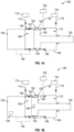
- FIGS. 1A-1B schematic illustrations of a fail-fixed position actuator system 100 in accordance with an embodiment of the present invention are shown.
- the fail-fixed position actuator system 100 is suitable for an aircraft and may be used onboard aircraft to perform an actuating operation through actuation or movement of a piston 102 within a housing 104.
- the piston 102 includes a piston head 106 that is configured to have hydraulic pressure applied thereto such that the piston head 106 translates or otherwise moves within the housing 104.
- the housing 104 defines a retract cavity 108 and an extend cavity 110 which are defined on opposite sides of the piston head 106.
- the retract cavity 108 and the extend cavity are each hydraulically (and/or fluidly) coupled to respective pressure sources which can be controlled to increase or decrease a pressure within the cavities 108, 110.
- the retract cavity 108 may be coupled (hydraulically and/or fluidly) to a first high pressure source 112 by a first high pressure line 114.
- the extend cavity 110 may be coupled (hydraulically and/or fluidly) to a second high pressure source 116 by a second high pressure line 118.
- an electric motor 120 is configured to translate a windowed sleeve 122 axially to a desired actuator position.
- the electric motor 120 may be coupled to or attached to the housing 104 or may be arranged in proximity to the housing 104.
- the electric motor 120 may be operably coupled to the sleeve 122 to control movement of the sleeve 122 within the housing 104.
- the sleeve 122 is arranged within the housing 104 and is positioned such that the piston head 106 may slidingly and sealingly engage with the sleeve 122.
- the sleeve 122 may be moved with the piston 102 such that the piston head 106 remains in sealing engagement with the sleeve 122 (shown in FIG. 1A ).
- the piston 102 will perform an extension actuation (e.g., to the right on the page).
- the motor 120 will drive movement of the sleeve 122 such that the sleeve 122 moves with the piston head 106.
- the piston head 106 includes one or more seals 124.
- the sleeve 122 is a windowed sleeve, including a sleeve aperture 126.
- the piston head 106 In the normal position ( FIG. 1A ), the piston head 106 is aligned with the sleeve aperture 126 and is sealingly engaged with the sleeve 122 by the seals 124.
- a low pressure cavity 128 is defined between the piston head 106 and the sleeve 122 on a first side and a portion of the housing 104 on a second side.
- the low pressure cavity 128 is hydraulically and/or fluidly connected to a low pressure source 130 by a low pressure line 132. As such, during normal operation, the low pressure cavity 128 is filled with low pressure fluid, and the two cavities 108, 110 are filled with high pressure fluid.
- the motor 120 may be operated to control the position of the sleeve 122 and particularly the sleeve aperture 126 within the housing 104. If the piston head 106 is moved away from the sleeve aperture 126, the low pressure cavity 128 will be exposed to and fluidly connected to either the retract cavity 108 or the extend cavity 110. When the low pressure cavity 128 is in fluid communication with one of the cavities 108, 110, the pressure within that cavity 108, 110 will be decreased and the pressure on the other side of the piston head 106 will be relatively higher. This pressure differential across the piston head 106 will cause the piston head 106 to move toward the lower pressure side and thus the piston head 106 may be aligned again with the sleeve aperture 126. That is, when the piston head 106 is moved to cover the sleeve aperture 126, the forces on opposing sides of the piston head 106 may be equalized and ensure that the piston 102 is held in a desired position.
- the position may be corrected through the positioning of the sleeve 122 within the housing 104.
- the sleeve 122 may be moved (by operation of the motor 12) to position the sleeve aperture 126 at a location that is desired for the piston head 106 to be located.
- the piston head 106 is moved, such as due to an external load application to the piston 102, the sleeve aperture 126 will be exposed to one of the actuator cavities (i.e., the retract cavity 108 or the extend cavity 110) to low pressure. This exposure to low pressure will cause a pressure differential and the piston head 106 will be caused to move until the sleeve aperture 126 is covered by the piston head 106 and the associated seals 124.
- the motor 120 may be operably coupled to the sleeve 122 and configured to control movement of the sleeve 122 within the housing 104 through a control connection 134.
- the control connection 134 may be a drive shaft, induction coil, magnetic system or the like that is configured to cause movement of the sleeve 122 within the housing 104.
- a linear motor and worm gear may be configured to drive the position of the sleeve 122.
- the motor 120 may be an electric motor that is supplied with electrical power from other sources onboard an aircraft, as will be appreciated by those of skill in the art.
- the motor 120 is configured to control the position of the sleeve 122 within the housing 104 and specifically the location of the sleeve aperture 126.
- the sleeve aperture 126 defines the position that the piston head 106 should be located in a force balance between the retract cavity 108 and the extend cavity 110. As such, if the piston head 106 is not located at the appropriate position, the exposure of the low pressure cavity 128 to one of the retract cavity 108 or the extend cavity 110 will cause movement of the piston head 106 such that the sleeve aperture 126 is covered by the piston head 106. As such, load is balanced passively in the event of a failure of the fail-fixed position actuator system 100 (e.g., loss of electrical power). Accordingly, the actuation of the fail-fixed position actuator system 100 may be maintained in a last-issued command position based on the location of the sleeve 122, the sleeve aperture 126, and the piston head 106.
- a fail-fixed hydraulic actuator containing a windowed sleeve (sleeve aperture) that is translated by a motor (e.g., linear electric motor). Both extend and retract cavities are connected to high pressure via respective orifices to high pressure sources. When moved, the sleeve exposes one of the cavities of the hydraulic actuator to low pressure through the sleeve aperture. This exposure to low pressure causes the actuator to slew until the sleeve aperture is covered (or partially covered) and the actuator is in force balance with an external load (e.g., applied to the piston).
- a windowed sleeve sleeve aperture
- a motor e.g., linear electric motor
- FIG. 1B illustrates the low pressure cavity 128 fluidly connected to the extend cavity 110 through the sleeve aperture 126
- the piston head 106 may end on the opposite side of the sleeve aperture 126 such that the retract cavity 108 fluidly couples to the low pressure cavity 128.
- the fail-fixed position actuator system 100 can provide a fail-fixed position of the piston 102 relative to the housing 104, regardless of the position of the piston head 106 at the time of the failure (e.g., loss of electrical power).
- the location of the sleeve aperture 126 defines the final fail position of the piston head 106 and thus the piston 102.
- the sleeve 122 is configured to move within the housing 104.
- the sleeve 122 may sealingly engage with an interior surface of the housing 104 using one or more seals 136.
- the seals 136 are provided to ensure that there is no fluid or pressure bleed between the low pressure cavity 128 and the high pressure cavities (e.g., retract cavity 108, extend cavity 110) except when the sleeve aperture 126 is exposed to one of the cavities 108, 110.
- the motor 120 that drives the position of the sleeve 122 within the housing 104 may include a controller 138 (or may be in communication with a controller external thereto).
- the controller 138 may be configured to control the movement and position of the sleeve 122 within the housing 104.
- the piston 102 may include a position sensor 140 that provides information regarding the current position of the piston 102 or piston head 106 within the housing 104.
- the position sensor 140 may be in communication with the controller 138 such that the controller 138 receives the position information of the piston 102 and controls the position of the sleeve 122 relative thereto.
- the position sensor 140 is shown with the position sensor 140 as part of the piston head 106, such location is not to be limiting.
- Optical position sensors may be employed without departing from the scope of the present invention.
- Optical position sensors, proximity sensors, direct coupling to the piston head and/or piston shaft, control data from an actuator controller, or the like may all be used individually and/or in combination to monitor the position of the piston within the housing.
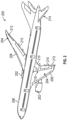
- FIG. 2 illustrates an example of an aircraft 200 having aircraft engines surrounded by (or otherwise carried in) nacelles 202.
- the aircraft 200 includes wings 204 that extend from an aircraft fuselage 206.
- Each wing 204 may include one or more slats 208 on a forward edge or leading edge and one or more flaps 210 on an aft, rear, or trailing edge thereof.
- the wings 204 may also include ailerons 212 on the trailing edges, as will be appreciated by those of skill in the art.
- the aircraft 200 as shown, includes a tail structure 214 which can include various flaps, ailerons, slats, and the like, as will be appreciated by those of skill in the art.
- the flaps, slats, ailerons, and the like are generally referred to herein as "aerostructures" as they are movable under aircraft power systems and are configured to control flight and motion of the aircraft 200.
- An aerostructure actuator system 216 may be connected to one or more of the aerostructures.
- each wing 204 and the tail structure 214 may include one or more aerostructure actuator systems 216.
- the aerostructure actuator systems 216 may be operably connected to the various aerostructures and configured control the operation/position of the aerostructures to control flight of the aircraft 200.
- the aerostructure actuator systems 216 can include one or more actuator systems such as shown and described above with respect to FIGS. 1A-1B .
- the engines of the aircraft 200 may include various actuators and control mechanisms that can incorporate one or more actuator systems such as shown and described above with respect to FIGS. 1A-1B .
- the described actuator systems of the present disclosure may be incorporated into aircraft engine systems and/or aircraft flight systems. It will be appreciated that such actuator systems as described herein may be used for other purposes onboard aircraft, such as for actuating doors, landing gear, or the like.
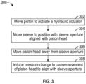
- FIG. 3 a flow process 300 for operating the actuator system in accordance with an embodiment of the present invention.
- the flow process 300 is designed for operating an actuator system such as that shown and described above.
- the flow process 300 may be performed using a controller or the like that is configured to monitor a position of the piston within the housing and also control the position of the sleeve within the housing, through control and operation of a motor or other driving mechanism.
- the flow process 300 operation is functional with a hydraulic actuator having the piston actuator arranged within the housing with the sleeve positioned relative to the piston head within the housing.
- the sleeve includes the sleeve aperture and is drivingly moveable within the housing of the hydraulic actuator by a motor operably connected to the sleeve.
- the positioning of the sleeve aperture within the housing is controlled to ensure that the piston head is placed where needed in the event of a failure of the actuator system. That is, the positioning of the aperture ensures a fixed end or stop position of the piston head in the event of failure of the system (as compared to ending at a full extension or full retraction).
- the piston is caused to move within the housing to actuate the hydraulic actuator.
- the control of the motion of the piston may be achieved through control of hydraulic and/or fluid pressure on opposing sides of the piston head.
- the piston may be arranged within the housing and an electrohydraulic servo valve may be operably coupled thereto to control fluid and/or hydraulic pressure on opposing sides of the piston head to control actuation of the actuator.
- the piston will slide within the sleeve, as shown and described above, and is applicable for a case where an external load causes the piston (and piston head) to move.
- a new actuator position is desired and the flow process will start with positioning the sleeve to a new position, thus exposing the piston head to the force imbalance, as described herein.
- a motor is operated to control the position of the sleeve within the housing.
- the movement of the sleeve may be substantially similar to the movement of the piston head within the housing. As such, during normal operation, the sleeve may not impact the operation of the piston in the process of actuating the hydraulic actuator.
- the movement of the sleeve within the housing is made to ensure that the sleeve aperture is located at a desired location at all times. For example, the position of the sleeve aperture may be moved to ensure that in the event of a failure of the hydraulic aperture that the sleeve aperture is located at a position desired for the piston to stop and stay and hold the piston in the desired position due to force balancing.
- the piston head is moved away from the sleeve aperture.
- Such offset of the piston from the sleeve aperture may occur due to a failure of some kind related to the hydraulic actuator.
- the pressures on opposing sides of the piston head may be unbalanced, thus causing the piston head to move toward one end of the housing, and thus offset the piston head from the sleeve aperture.
- a pressure change is induced in the housing to cause the piston head to move and align with the sleeve aperture.
- the sleeve aperture is exposed and thus allows for hydraulic and/or fluid connection between a low pressure cavity of the hydraulic actuator and one of the high pressure cavities thereof. This connection causes a pressure change (decrease) in the high pressure cavity that is connected to the low pressure cavity, thus causing movement of the piston head to realign with the sleeve aperture.
- embodiments of the present invention provide for improved actuators and fail-fixed position for such actuators.
- the hydraulic actuator upon failure of electrical power, the hydraulic actuator will remain in a last commanded position and will retain an ability to oppose variable external loads. This is achieved through a passive fail-fixed position process that is achieved through a moveable sleeve within the actuator with an aperture or window that, when exposed to a cavity of the actuator, will allow low pressure into the cavity and thus cause movement of the piston to the fail-fixed position.
- embodiments provided herein provide for a passive failure operation for an actuator to ensure the actuator stays in a last commanded position at the time of failure, whether the piston of the actuator is at an end stop or between ends of the actuator. Further, because the fail-fixed position is maintained by a force balance, after the failure, the actuator may remain in the fixed position and resist or oppose external loads even without a supply of power.
- connection can include an indirect “connection” and a direct “connection”.
- each block in the flowchart or block diagrams may represent a module, segment, or portion of instructions, which comprises one or more executable instructions for implementing the specified logical function(s).
- the functions noted in the block may occur out of the order noted in the figures.
- two blocks shown in succession may, in fact, be executed substantially concurrently (or simultaneously), or the blocks may sometimes be executed in the reverse order, depending upon the functionality involved.
Landscapes
- Engineering & Computer Science (AREA)
- Physics & Mathematics (AREA)
- Fluid Mechanics (AREA)
- Mechanical Engineering (AREA)
- General Engineering & Computer Science (AREA)
- Chemical & Material Sciences (AREA)
- Analytical Chemistry (AREA)
- Fluid-Pressure Circuits (AREA)
Claims (15)
- Système d'actionneur hydraulique à fixation intégrée pour un aéronef, le système d'actionneur hydraulique à fixation intégrée comprenant :un actionneur hydraulique ayant un boîtier (104) avec un piston (102) disposé à l'intérieur du boîtier (104), le piston (102) ayant une tête de piston (106) séparant le boîtier (104) en une cavité repliée et une cavité étendue ;un manchon (122) disposé à l'intérieur du boîtier (104) et pouvant se déplacer à l'intérieur de celui-ci, le manchon (122) ayant une ouverture de manchon (126) qui est alignée avec la tête de piston (106) pendant le fonctionnement normal ; etun mécanisme d'entraînement conçu pour entraîner un déplacement du manchon (122) afin de maintenir l'alignement entre l'ouverture de manchon (126) et la tête de piston (106),dans lequel une cavité basse pression est définie entre une surface interne du boîtier (104) et le manchon (122), etdans lequel, lorsque la tête de piston (106) est décalée par rapport à l'ouverture de manchon (126), la cavité basse pression est reliée hydrauliquement à l'une de la cavité repliée ou de la cavité étendue afin de provoquer une différence de pression avec l'autre de la cavité étendue et de la cavité repliée et de provoquer un déplacement de la tête de piston (106) pour s'aligner avec l'ouverture de manchon (126).
- Système d'actionneur hydraulique à fixation intégrée selon la revendication 1, comprenant en outre un dispositif de commande conçu pour commander le fonctionnement du mécanisme d'entraînement.
- Système d'actionneur hydraulique à fixation intégrée selon la revendication 2, dans lequel le dispositif de commande est intégré dans le mécanisme d'entraînement.
- Système d'actionneur hydraulique à fixation intégrée selon la revendication 2, comprenant en outre un capteur de position conçu pour détecter une position d'au moins l'un du piston (102) et de la tête de piston (106) à l'intérieur du boîtier (104), dans lequel le capteur de position est conçu pour communiquer avec le dispositif de commande.
- Système d'actionneur hydraulique à fixation intégrée selon l'une quelconque revendication précédente, comprenant en outre un capteur de position conçu pour détecter une position d'au moins l'un du piston (102) et de la tête de piston (106) à l'intérieur du boîtier (104).
- Système d'actionneur hydraulique à fixation intégrée selon l'une quelconque revendication précédente, dans lequel le mécanisme d'entraînement est un moteur électrique.
- Système d'actionneur hydraulique à fixation intégrée selon l'une quelconque revendication précédente, comprenant en outre au moins un joint conçu pour mettre en prise de manière étanche le manchon (122) avec le boîtier (104) et définir la cavité basse pression.
- Système d'actionneur hydraulique à fixation intégrée selon l'une quelconque revendication précédente, comprenant en outre une première source de haute pression accouplée hydrauliquement à la cavité repliée, une seconde source de haute pression accouplée hydrauliquement à la cavité étendue, et une source de basse pression accouplée hydrauliquement à la cavité basse pression, dans lequel une pression des première et seconde sources de haute pression est supérieure à une pression de la source de basse pression.
- Système d'actionneur hydraulique à fixation intégrée selon l'une quelconque revendication précédente, comprenant en outre un système d'aéronef, dans lequel le piston (102) est conçu pour actionner un composant du système d'aéronef.
- Procédé de fonctionnement du système d'actionneur hydraulique à fixation intégrée pour un aéronef selon l'une quelconque revendication précédente, le procédé comprenant :le fonctionnement de l'actionneur afin d'effectuer une opération d'actionnement ;le déplacement du manchon (122) à l'intérieur du boîtier (104), pendant le fonctionnement normal, afin de maintenir l'alignement entre la tête de piston (106) et l'ouverture de manchon (126) du manchon (122) ;la liaison hydraulique de la cavité basse pression définie par le manchon (122) à l'une de la cavité repliée ou de la cavité étendue de l'actionneur lorsque la tête de piston (106) est décalée par rapport à l'ouverture de manchon (126) ; etle déplacement de la tête de piston (106) pour s'aligner avec l'ouverture de manchon (126) en réponse à la liaison entre la cavité basse pression et celle de la cavité repliée ou de la cavité étendue.
- Procédé selon la revendication 10, comprenant en outre la surveillance d'une position d'au moins l'un de la tête de piston (106) ou du piston (102) à l'intérieur du boîtier (104) de l'actionneur.
- Procédé selon la revendication 10 ou 11, dans lequel le déplacement du manchon (122) est commandé par le mécanisme d'entraînement accouplé de manière opérationnelle à celui-ci.
- Procédé selon l'une quelconque des revendications 10 à 12, comprenant en outre :la détection d'une position de la tête de piston (106) à l'intérieur de l'actionneur ; etla commande de la position de l'ouverture de manchon (126) afin de maintenir l'alignement de l'ouverture de manchon (126) et de la tête de piston (106) en réponse à la position détectée.
- Procédé selon l'une quelconque des revendications 10 à 13, dans lequel le déplacement de la tête de piston (106) pour s'aligner avec l'ouverture de manchon (126) fait suite à une panne de courant de l'actionneur, et/ou dans lequel la cavité basse pression a une pression inférieure à une pression de la cavité repliée ou de la cavité étendue.
- Procédé selon l'une quelconque des revendications 10 à 14, comprenant en outre :l'alimentation de la cavité repliée avec une haute pression à partir d'une première source de haute pression ;l'alimentation de la cavité étendue avec une haute pression à partir d'une seconde source de haute pression ; etl'alimentation de la cavité basse pression avec une basse pression à partir d'une source de basse pression,dans lequel la basse pression est inférieure à la pression de l'une ou l'autre des première et seconde sources de haute pression.
Applications Claiming Priority (1)
| Application Number | Priority Date | Filing Date | Title |
|---|---|---|---|
| US17/728,283 US11619246B1 (en) | 2022-04-25 | 2022-04-25 | Fail-fixed hydraulic actuator |
Publications (2)
| Publication Number | Publication Date |
|---|---|
| EP4269811A1 EP4269811A1 (fr) | 2023-11-01 |
| EP4269811B1 true EP4269811B1 (fr) | 2025-06-25 |
Family
ID=85571350
Family Applications (1)
| Application Number | Title | Priority Date | Filing Date |
|---|---|---|---|
| EP23161219.3A Active EP4269811B1 (fr) | 2022-04-25 | 2023-03-10 | Actionneur hydraulique à fixation intégrée |
Country Status (2)
| Country | Link |
|---|---|
| US (1) | US11619246B1 (fr) |
| EP (1) | EP4269811B1 (fr) |
Families Citing this family (1)
| Publication number | Priority date | Publication date | Assignee | Title |
|---|---|---|---|---|
| CN119687050B (zh) * | 2024-12-10 | 2025-11-18 | 北京精密机电控制设备研究所 | 一种基于伺服电机柱塞泵的液压促动器 |
Family Cites Families (17)
| Publication number | Priority date | Publication date | Assignee | Title |
|---|---|---|---|---|
| US2825307A (en) * | 1956-01-19 | 1958-03-04 | Monarch Machine Tool Co | Hydraulic control system |
| GB982003A (en) * | 1962-06-02 | 1965-02-03 | Frederick George Grisley | Improvements in hydraulic or pneumatic programming apparatus |
| US4876906A (en) * | 1986-11-20 | 1989-10-31 | Sundstrand Corporation | Non-jamming actuator system |
| US4745815A (en) * | 1986-12-08 | 1988-05-24 | Sundstrand Corporation | Non-jamming screw actuator system |
| US5551478A (en) | 1994-10-21 | 1996-09-03 | United Technologies Corporation | Multiplexing hydraulic control network with latching valves |
| US5735122A (en) | 1996-11-29 | 1998-04-07 | United Technologies Corporation | Actuator with failfixed zero drift |
| GB9911526D0 (en) * | 1999-05-19 | 1999-07-14 | Lucas Ind Plc | Actuator |
| US6953084B2 (en) | 2003-01-10 | 2005-10-11 | Woodward Governor Company | Actuator for well-head valve or other similar applications and system incorporating same |
| US7475537B2 (en) | 2006-06-05 | 2009-01-13 | Woodward Governor Company | Maintaining the position of an electro-hydraulic servo valve controlled device upon loss of position command |
| US7836676B2 (en) | 2007-06-04 | 2010-11-23 | Honeywell International Inc. | Fuel metering valve back-up position control system |
| JP5517368B2 (ja) * | 2012-09-03 | 2014-06-11 | カヤバ工業株式会社 | アクチュエータ |
| US20160333901A1 (en) | 2015-05-15 | 2016-11-17 | Triumph Engine Control Systems, Llc | Fail fixed actuator |
| GB2540567A (en) * | 2015-07-21 | 2017-01-25 | Airbus Operations Ltd | An actuator |
| DE102016105193B4 (de) * | 2016-03-21 | 2020-11-12 | Deutsches Zentrum für Luft- und Raumfahrt e.V. | Störsicherer elektromechanischer Aktuator, Verfahren zu dessen Betrieb und Verwendung eines elektromechanischen Aktuators |
| US10619654B2 (en) | 2017-05-05 | 2020-04-14 | Hamilton Sundstrand Corporation | Fail-fixed hydraulic actuator |
| US11242875B2 (en) | 2020-03-05 | 2022-02-08 | Honeywell International Inc. | System that maintains the last commanded position of device controlled by a two-stage, four-way electrohydraulic servo valve upon power interruption |
| US11391301B2 (en) | 2020-04-14 | 2022-07-19 | Honeywell International Inc. | Electrohydraulic poppet valve device control that maintains the last commanded position of a device upon power interruption and provides back-up position control |
-
2022
- 2022-04-25 US US17/728,283 patent/US11619246B1/en active Active
-
2023
- 2023-03-10 EP EP23161219.3A patent/EP4269811B1/fr active Active
Also Published As
| Publication number | Publication date |
|---|---|
| US11619246B1 (en) | 2023-04-04 |
| EP4269811A1 (fr) | 2023-11-01 |
Similar Documents
| Publication | Publication Date | Title |
|---|---|---|
| EP1846291B1 (fr) | Vanne concentrique double a double moteur | |
| US10538310B2 (en) | Near synchronous distributed hydraulic motor driven actuation system | |
| JP3162139B2 (ja) | 好ましくは非常時に機能するハイドロスタティックモードの流体圧アクチュエータ及び該アクチュエータを備えた操縦システム | |
| EP3620374B1 (fr) | Systèmes de volet d'aile d'un bord de fuite distribué | |
| EP3208189B1 (fr) | Système de surveillance de mouvement de surface de commande aérodynamique | |
| JP7245643B2 (ja) | 分散型後縁翼フラップシステム | |
| EP2465770A2 (fr) | Réglage des ailes à courbure variable pour la configuration optimum de décollage et d'atterrissage | |
| EP4265921A1 (fr) | Actionneur hydraulique comprenant un piston à têtes multiples pour transmission hydraulique | |
| US10190605B2 (en) | Nacelle for an aircraft turbojet engine provided with a hydraulic roto-linear actuator of a thrust reverser and of a variable-section nozzle | |
| US11391384B2 (en) | Hydraulic actuator force fight mitigation mechanism | |
| EP4269811B1 (fr) | Actionneur hydraulique à fixation intégrée | |
| US11255294B2 (en) | Thrust reverser velocity control valve | |
| EP4265924A1 (fr) | Actionneur avec soupape d'arrêt | |
| EP3767112B1 (fr) | Agencement de commande d'actionneur | |
| KR102271778B1 (ko) | 공압 샤프트 위치 설정 시스템 | |
| US20090013862A1 (en) | Dual linear actuator | |
| EP2476613A2 (fr) | Système d'actionneur hydraulique pour aéronefs | |
| US9260179B2 (en) | Propeller and system of counter-rotating propellers comprising improved means for limiting pitch, and a turbine engine comprising them | |
| EP1785347A2 (fr) | Système d'actionnement reconfigurable pour surfaces de commande de vol et procédé | |
| US7668627B2 (en) | Mechanical flight control auxiliary power assist system | |
| EP4269812A1 (fr) | Configuration d'actionneur à verrouillage hydraulique | |
| Sheorey | Design and Development of Feedback Control Hydraulic Airbrake Actuators for a High Performance Aircraft |
Legal Events
| Date | Code | Title | Description |
|---|---|---|---|
| PUAI | Public reference made under article 153(3) epc to a published international application that has entered the european phase |
Free format text: ORIGINAL CODE: 0009012 |
|
| STAA | Information on the status of an ep patent application or granted ep patent |
Free format text: STATUS: THE APPLICATION HAS BEEN PUBLISHED |
|
| AK | Designated contracting states |
Kind code of ref document: A1 Designated state(s): AL AT BE BG CH CY CZ DE DK EE ES FI FR GB GR HR HU IE IS IT LI LT LU LV MC ME MK MT NL NO PL PT RO RS SE SI SK SM TR |
|
| STAA | Information on the status of an ep patent application or granted ep patent |
Free format text: STATUS: REQUEST FOR EXAMINATION WAS MADE |
|
| 17P | Request for examination filed |
Effective date: 20240429 |
|
| RBV | Designated contracting states (corrected) |
Designated state(s): AL AT BE BG CH CY CZ DE DK EE ES FI FR GB GR HR HU IE IS IT LI LT LU LV MC ME MK MT NL NO PL PT RO RS SE SI SK SM TR |
|
| GRAP | Despatch of communication of intention to grant a patent |
Free format text: ORIGINAL CODE: EPIDOSNIGR1 |
|
| STAA | Information on the status of an ep patent application or granted ep patent |
Free format text: STATUS: GRANT OF PATENT IS INTENDED |
|
| INTG | Intention to grant announced |
Effective date: 20250206 |
|
| GRAS | Grant fee paid |
Free format text: ORIGINAL CODE: EPIDOSNIGR3 |
|
| GRAA | (expected) grant |
Free format text: ORIGINAL CODE: 0009210 |
|
| STAA | Information on the status of an ep patent application or granted ep patent |
Free format text: STATUS: THE PATENT HAS BEEN GRANTED |
|
| AK | Designated contracting states |
Kind code of ref document: B1 Designated state(s): AL AT BE BG CH CY CZ DE DK EE ES FI FR GB GR HR HU IE IS IT LI LT LU LV MC ME MK MT NL NO PL PT RO RS SE SI SK SM TR |
|
| REG | Reference to a national code |
Ref country code: GB Ref legal event code: FG4D |
|
| REG | Reference to a national code |
Ref country code: CH Ref legal event code: EP |
|
| REG | Reference to a national code |
Ref country code: DE Ref legal event code: R096 Ref document number: 602023004182 Country of ref document: DE |
|
| REG | Reference to a national code |
Ref country code: CH Ref legal event code: EP |
|
| REG | Reference to a national code |
Ref country code: IE Ref legal event code: FG4D |
|
| PG25 | Lapsed in a contracting state [announced via postgrant information from national office to epo] |
Ref country code: FI Free format text: LAPSE BECAUSE OF FAILURE TO SUBMIT A TRANSLATION OF THE DESCRIPTION OR TO PAY THE FEE WITHIN THE PRESCRIBED TIME-LIMIT Effective date: 20250625 |
|
| REG | Reference to a national code |
Ref country code: LT Ref legal event code: MG9D |
|
| PG25 | Lapsed in a contracting state [announced via postgrant information from national office to epo] |
Ref country code: GR Free format text: LAPSE BECAUSE OF FAILURE TO SUBMIT A TRANSLATION OF THE DESCRIPTION OR TO PAY THE FEE WITHIN THE PRESCRIBED TIME-LIMIT Effective date: 20250926 Ref country code: NO Free format text: LAPSE BECAUSE OF FAILURE TO SUBMIT A TRANSLATION OF THE DESCRIPTION OR TO PAY THE FEE WITHIN THE PRESCRIBED TIME-LIMIT Effective date: 20250925 |
|
| PG25 | Lapsed in a contracting state [announced via postgrant information from national office to epo] |
Ref country code: BG Free format text: LAPSE BECAUSE OF FAILURE TO SUBMIT A TRANSLATION OF THE DESCRIPTION OR TO PAY THE FEE WITHIN THE PRESCRIBED TIME-LIMIT Effective date: 20250625 |
|
| PG25 | Lapsed in a contracting state [announced via postgrant information from national office to epo] |
Ref country code: HR Free format text: LAPSE BECAUSE OF FAILURE TO SUBMIT A TRANSLATION OF THE DESCRIPTION OR TO PAY THE FEE WITHIN THE PRESCRIBED TIME-LIMIT Effective date: 20250625 |
|
| PG25 | Lapsed in a contracting state [announced via postgrant information from national office to epo] |
Ref country code: RS Free format text: LAPSE BECAUSE OF FAILURE TO SUBMIT A TRANSLATION OF THE DESCRIPTION OR TO PAY THE FEE WITHIN THE PRESCRIBED TIME-LIMIT Effective date: 20250925 |
|
| PG25 | Lapsed in a contracting state [announced via postgrant information from national office to epo] |
Ref country code: LV Free format text: LAPSE BECAUSE OF FAILURE TO SUBMIT A TRANSLATION OF THE DESCRIPTION OR TO PAY THE FEE WITHIN THE PRESCRIBED TIME-LIMIT Effective date: 20250625 |
|
| REG | Reference to a national code |
Ref country code: NL Ref legal event code: MP Effective date: 20250625 |
|
| PG25 | Lapsed in a contracting state [announced via postgrant information from national office to epo] |
Ref country code: NL Free format text: LAPSE BECAUSE OF FAILURE TO SUBMIT A TRANSLATION OF THE DESCRIPTION OR TO PAY THE FEE WITHIN THE PRESCRIBED TIME-LIMIT Effective date: 20250625 |
|
| PG25 | Lapsed in a contracting state [announced via postgrant information from national office to epo] |
Ref country code: PT Free format text: LAPSE BECAUSE OF FAILURE TO SUBMIT A TRANSLATION OF THE DESCRIPTION OR TO PAY THE FEE WITHIN THE PRESCRIBED TIME-LIMIT Effective date: 20251027 |
|
| REG | Reference to a national code |
Ref country code: AT Ref legal event code: MK05 Ref document number: 1806690 Country of ref document: AT Kind code of ref document: T Effective date: 20250625 |
|
| PG25 | Lapsed in a contracting state [announced via postgrant information from national office to epo] |
Ref country code: IS Free format text: LAPSE BECAUSE OF FAILURE TO SUBMIT A TRANSLATION OF THE DESCRIPTION OR TO PAY THE FEE WITHIN THE PRESCRIBED TIME-LIMIT Effective date: 20251025 |
|
| PG25 | Lapsed in a contracting state [announced via postgrant information from national office to epo] |
Ref country code: SM Free format text: LAPSE BECAUSE OF FAILURE TO SUBMIT A TRANSLATION OF THE DESCRIPTION OR TO PAY THE FEE WITHIN THE PRESCRIBED TIME-LIMIT Effective date: 20250625 Ref country code: AT Free format text: LAPSE BECAUSE OF FAILURE TO SUBMIT A TRANSLATION OF THE DESCRIPTION OR TO PAY THE FEE WITHIN THE PRESCRIBED TIME-LIMIT Effective date: 20250625 |
|
| PG25 | Lapsed in a contracting state [announced via postgrant information from national office to epo] |
Ref country code: CZ Free format text: LAPSE BECAUSE OF FAILURE TO SUBMIT A TRANSLATION OF THE DESCRIPTION OR TO PAY THE FEE WITHIN THE PRESCRIBED TIME-LIMIT Effective date: 20250625 |
|
| PG25 | Lapsed in a contracting state [announced via postgrant information from national office to epo] |
Ref country code: PL Free format text: LAPSE BECAUSE OF FAILURE TO SUBMIT A TRANSLATION OF THE DESCRIPTION OR TO PAY THE FEE WITHIN THE PRESCRIBED TIME-LIMIT Effective date: 20250625 |
|
| PG25 | Lapsed in a contracting state [announced via postgrant information from national office to epo] |
Ref country code: EE Free format text: LAPSE BECAUSE OF FAILURE TO SUBMIT A TRANSLATION OF THE DESCRIPTION OR TO PAY THE FEE WITHIN THE PRESCRIBED TIME-LIMIT Effective date: 20250625 |
|
| PG25 | Lapsed in a contracting state [announced via postgrant information from national office to epo] |
Ref country code: SK Free format text: LAPSE BECAUSE OF FAILURE TO SUBMIT A TRANSLATION OF THE DESCRIPTION OR TO PAY THE FEE WITHIN THE PRESCRIBED TIME-LIMIT Effective date: 20250625 |
|
| PG25 | Lapsed in a contracting state [announced via postgrant information from national office to epo] |
Ref country code: ES Free format text: LAPSE BECAUSE OF FAILURE TO SUBMIT A TRANSLATION OF THE DESCRIPTION OR TO PAY THE FEE WITHIN THE PRESCRIBED TIME-LIMIT Effective date: 20250625 |
|
| PG25 | Lapsed in a contracting state [announced via postgrant information from national office to epo] |
Ref country code: DK Free format text: LAPSE BECAUSE OF FAILURE TO SUBMIT A TRANSLATION OF THE DESCRIPTION OR TO PAY THE FEE WITHIN THE PRESCRIBED TIME-LIMIT Effective date: 20250625 |
|
| PGFP | Annual fee paid to national office [announced via postgrant information from national office to epo] |
Ref country code: DE Payment date: 20260219 Year of fee payment: 4 |
|
| PG25 | Lapsed in a contracting state [announced via postgrant information from national office to epo] |
Ref country code: IT Free format text: LAPSE BECAUSE OF FAILURE TO SUBMIT A TRANSLATION OF THE DESCRIPTION OR TO PAY THE FEE WITHIN THE PRESCRIBED TIME-LIMIT Effective date: 20250625 |
|
| PLBE | No opposition filed within time limit |
Free format text: ORIGINAL CODE: 0009261 |
|
| STAA | Information on the status of an ep patent application or granted ep patent |
Free format text: STATUS: NO OPPOSITION FILED WITHIN TIME LIMIT |