EP4269837B1 - Agencement d'accouplement et dispositif de transmission doté d'un tel agencement d'accouplement - Google Patents
Agencement d'accouplement et dispositif de transmission doté d'un tel agencement d'accouplement Download PDFInfo
- Publication number
- EP4269837B1 EP4269837B1 EP22170122.0A EP22170122A EP4269837B1 EP 4269837 B1 EP4269837 B1 EP 4269837B1 EP 22170122 A EP22170122 A EP 22170122A EP 4269837 B1 EP4269837 B1 EP 4269837B1
- Authority
- EP
- European Patent Office
- Prior art keywords
- projections
- parking lock
- fluid
- coupling assembly
- leadthrough
- Prior art date
- Legal status (The legal status is an assumption and is not a legal conclusion. Google has not performed a legal analysis and makes no representation as to the accuracy of the status listed.)
- Active
Links
Images


Classifications
-
- F—MECHANICAL ENGINEERING; LIGHTING; HEATING; WEAPONS; BLASTING
- F16—ENGINEERING ELEMENTS AND UNITS; GENERAL MEASURES FOR PRODUCING AND MAINTAINING EFFECTIVE FUNCTIONING OF MACHINES OR INSTALLATIONS; THERMAL INSULATION IN GENERAL
- F16H—GEARING
- F16H57/00—General details of gearing
- F16H57/02—Gearboxes; Mounting gearing therein
- F16H57/027—Gearboxes; Mounting gearing therein characterised by means for venting gearboxes, e.g. air breathers
-
- F—MECHANICAL ENGINEERING; LIGHTING; HEATING; WEAPONS; BLASTING
- F16—ENGINEERING ELEMENTS AND UNITS; GENERAL MEASURES FOR PRODUCING AND MAINTAINING EFFECTIVE FUNCTIONING OF MACHINES OR INSTALLATIONS; THERMAL INSULATION IN GENERAL
- F16H—GEARING
- F16H63/00—Control outputs from the control unit to change-speed- or reversing-gearings for conveying rotary motion or to other devices than the final output mechanism
- F16H63/02—Final output mechanisms therefor; Actuating means for the final output mechanisms
- F16H63/30—Constructional features of the final output mechanisms
- F16H63/34—Locking or disabling mechanisms
- F16H63/3416—Parking lock mechanisms or brakes in the transmission
- F16H63/3425—Parking lock mechanisms or brakes in the transmission characterised by pawls or wheels
-
- F—MECHANICAL ENGINEERING; LIGHTING; HEATING; WEAPONS; BLASTING
- F16—ENGINEERING ELEMENTS AND UNITS; GENERAL MEASURES FOR PRODUCING AND MAINTAINING EFFECTIVE FUNCTIONING OF MACHINES OR INSTALLATIONS; THERMAL INSULATION IN GENERAL
- F16H—GEARING
- F16H63/00—Control outputs from the control unit to change-speed- or reversing-gearings for conveying rotary motion or to other devices than the final output mechanism
- F16H63/02—Final output mechanisms therefor; Actuating means for the final output mechanisms
- F16H63/30—Constructional features of the final output mechanisms
- F16H63/34—Locking or disabling mechanisms
- F16H63/3416—Parking lock mechanisms or brakes in the transmission
- F16H63/3458—Parking lock mechanisms or brakes in the transmission with electric actuating means, e.g. shift by wire
- F16H63/3466—Parking lock mechanisms or brakes in the transmission with electric actuating means, e.g. shift by wire using electric motors
-
- F—MECHANICAL ENGINEERING; LIGHTING; HEATING; WEAPONS; BLASTING
- F16—ENGINEERING ELEMENTS AND UNITS; GENERAL MEASURES FOR PRODUCING AND MAINTAINING EFFECTIVE FUNCTIONING OF MACHINES OR INSTALLATIONS; THERMAL INSULATION IN GENERAL
- F16L—PIPES; JOINTS OR FITTINGS FOR PIPES; SUPPORTS FOR PIPES, CABLES OR PROTECTIVE TUBING; MEANS FOR THERMAL INSULATION IN GENERAL
- F16L37/00—Couplings of the quick-acting type
- F16L37/08—Couplings of the quick-acting type in which the connection between abutting or axially overlapping ends is maintained by locking members
- F16L37/084—Couplings of the quick-acting type in which the connection between abutting or axially overlapping ends is maintained by locking members combined with automatic locking
- F16L37/088—Couplings of the quick-acting type in which the connection between abutting or axially overlapping ends is maintained by locking members combined with automatic locking by means of a split elastic ring
- F16L37/0885—Couplings of the quick-acting type in which the connection between abutting or axially overlapping ends is maintained by locking members combined with automatic locking by means of a split elastic ring with access to the split elastic ring from a radial or tangential opening in the coupling
-
- F—MECHANICAL ENGINEERING; LIGHTING; HEATING; WEAPONS; BLASTING
- F16—ENGINEERING ELEMENTS AND UNITS; GENERAL MEASURES FOR PRODUCING AND MAINTAINING EFFECTIVE FUNCTIONING OF MACHINES OR INSTALLATIONS; THERMAL INSULATION IN GENERAL
- F16L—PIPES; JOINTS OR FITTINGS FOR PIPES; SUPPORTS FOR PIPES, CABLES OR PROTECTIVE TUBING; MEANS FOR THERMAL INSULATION IN GENERAL
- F16L5/00—Devices for use where pipes, cables or protective tubing pass through walls or partitions
- F16L5/02—Sealing
- F16L5/10—Sealing by using sealing rings or sleeves only
-
- H—ELECTRICITY
- H02—GENERATION; CONVERSION OR DISTRIBUTION OF ELECTRIC POWER
- H02K—DYNAMO-ELECTRIC MACHINES
- H02K7/00—Arrangements for handling mechanical energy structurally associated with dynamo-electric machines, e.g. structural association with mechanical driving motors or auxiliary dynamo-electric machines
- H02K7/10—Structural association with clutches, brakes, gears, pulleys or mechanical starters
- H02K7/116—Structural association with clutches, brakes, gears, pulleys or mechanical starters with gears
- H02K7/1163—Structural association with clutches, brakes, gears, pulleys or mechanical starters with gears where at least two gears have non-parallel axes without having orbital motion
- H02K7/1166—Structural association with clutches, brakes, gears, pulleys or mechanical starters with gears where at least two gears have non-parallel axes without having orbital motion comprising worm and worm-wheel
-
- B—PERFORMING OPERATIONS; TRANSPORTING
- B60—VEHICLES IN GENERAL
- B60Y—INDEXING SCHEME RELATING TO ASPECTS CROSS-CUTTING VEHICLE TECHNOLOGY
- B60Y2200/00—Type of vehicle
- B60Y2200/90—Vehicles comprising electric prime movers
Definitions
- the invention relates to a coupling arrangement comprising a feedthrough element which can be inserted into an opening of the housing to form a fluid connection between the exterior and the interior of a housing, and a fluid guide element with a cup-shaped recess into which the feedthrough element can be inserted.
- Such a clutch arrangement can be used in a transmission device for an electrically driven vehicle.
- the transmission device can include a parking lock gear, a parking lock with a parking lock actuator for locking the parking lock gear, a transmission housing in which the parking lock gear and the parking lock are accommodated, and a pressure compensation device through which the interior of the parking lock actuator is fluidly connected to the exterior of the transmission housing.
- Integrating a parking lock into a transmission housing saves installation space, which is particularly limited when using the transmission device in a vehicle's electric drive system.
- this presents particular challenges due to the presence of lubricants and higher temperatures inside the transmission housing. It is important that the transmission oil in the transmission housing does not enter the parking lock actuator, for example, due to pressure differences between the interior of the parking lock actuator and the exterior of the transmission housing.
- the DE 10 2018 133 266 A1 describes a transmission device with a pressure compensation device.
- a coupling assembly that is part of a pressure compensation device is subject to stringent requirements regarding tightness.
- the coupling assembly must be easy to install and ensure reliable sealing.
- the fluid guide element has a recess into which the feedthrough element can be inserted or plugged.
- the feedthrough element must be automatically centered upon insertion into the fluid guide element to prevent tilting, which could lead to leaks.
- US 2010/052315 A1 discloses a coupling assembly comprising a female connector body and a male connector element. These are releasably connected to each other by a U-shaped retaining element. Axially behind the retaining element, corresponding notches and ribs are provided on the connector body and the male connector element, respectively, to prevent relative rotation.
- the invention is therefore based on the object of providing a coupling arrangement which is easy to assemble and ensures reliable sealing.
- the clutch assembly thus comprises the feedthrough element, which is inserted into an opening of a housing, in particular a transmission housing.
- the feedthrough element comprises the first row of radially projecting projections, which are distributed in the circumferential direction and, when installed, are located in the recess of the fluid conducting element.
- the first row of projections prevents the feedthrough element from tilting. Without this first row of projections, the feedthrough element could otherwise tilt slightly.
- the first row of projections aligns the feedthrough element so that it is inserted precisely centrally. At the same time, this ensures a secure and trouble-free seal.
- the first row of projections ensures a reliable seal, preventing fluid, in particular lubricant, located in the transmission housing from penetrating the parking lock actuator.
- the cup-shaped recess of the fluid guide element has radially inward-facing centering ribs distributed along its inner circumference.
- centering ribs are projections that support and center the outer end section of the feedthrough element in the fluid guide element.
- the fluid guide element has a sealing element designed as an O-ring, which ensures a seal between the fluid guide element and the feedthrough element. Due to the centering ribs, the feedthrough element cannot tilt, so that the sealing effect is permanently guaranteed.
- These centering ribs thus ensure that the feedthrough element is inserted precisely axially and cannot tilt or can only be tilted slightly, but without becoming leaky.
- the centering ribs ensure that the feedthrough element and the fluid guide element permanently maintain their relative position to one another.
- the coupling arrangement comprises a fastening element for connecting the feedthrough element and the fluid guide element to one another, wherein the fastening element comprises a deformable clip which passes through an opening of the cup-shaped recess and can be inserted into a recess of the feedthrough element.
- the invention provides that the first row of projections is arranged in front of the fastening element in the axial direction along which the feedthrough element can be inserted into the fluid-conducting element, and that the radially inward-facing centering ribs, distributed along the inner circumference of the cup-shaped recess, are arranged behind the fastening element in the axial direction along which the feedthrough element can be inserted into the fluid-conducting element.
- the centering ribs can preferably be arranged at a distal end of the cup-shaped recess.
- the first row of projections of the lead-through element comprises three in the circumferential direction distributed projections.
- the three projections prevent the feedthrough element from tilting and ensure a secure seal between the feedthrough element and the fluid guide element.
- the feedthrough element has two further axially spaced rows of radially projecting projections distributed in the circumferential direction for centering the feedthrough element in the opening of the housing.
- the coupling arrangement according to the invention can be provided with four projections each distributed in the circumferential direction. Having four projections each ensures secure centering of the feedthrough element when inserted into the fluid guide element.
- the projections of the first and/or second and/or third row have oblique, radially outwardly tapered side surfaces.
- a particularly reliable seal of the coupling arrangement according to the invention is achieved if an O-ring is arranged axially in front of and behind the two rows of projections.
- the feedthrough element and the fluid guide element can be manually plugged together and separated.
- the coupling arrangement comprises a pipe or hose connected to the fluid guide element, at the end of which a further fluid guide element is preferably arranged.
- the integration of multiple fluid guide elements reduces the number of required assembly steps.
- the coupling arrangement according to the invention can comprise a membrane fluidically connected to the feedthrough element, which membrane is preferably provided with a protective cap.
- the membrane enables the equalization of pressure differences that exist on both sides of the membrane.
- the invention relates to a transmission device for an electrically driven vehicle, comprising a parking lock gear, a parking lock with a parking lock actuator for blocking the parking lock gear, a transmission housing in which the parking lock gear and the parking lock are accommodated, a pressure compensation device by means of which the interior of the parking lock actuator is fluidly connected to the exterior of the transmission housing, wherein the pressure compensation device has a coupling arrangement of the type described, the feed-through element of which passes through the transmission housing and the fluid conducting element of which is connected to the interior of the parking lock actuator.
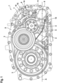
- Fig. 1 shows an embodiment of a transmission device with the transmission housing open.
- the transmission device 1 comprises a transmission element 2, which is coupled to further transmission elements 3 in order to transmit a torque transmitted by a shaft that is connected to the transmission element 2 in a rotationally fixed manner and covered by a bearing 4. Furthermore, a parking lock gear 5 of a parking lock 6 is attached to the transmission element 2, by which the transmission element 2 can be locked.
- the parking lock 6 further has a parking lock pawl 7, which can be brought into engagement with the parking lock gear 5 by means of a parking lock actuator 8 of the parking lock 6.
- the parking lock gear 5 has corresponding recesses on its outer circumference.
- the transmission elements 2, 3 and the parking lock 6 are accommodated in a transmission housing 9.
- the transmission device 1 has a lubricant bath, the normal operating level of which is indicated by a dashed line A in Fig. 1 is shown.
- the parking lock 6 is clearly partially immersed in the lubricant bath.
- Fig. 1 furthermore, a connection device comprising a cable arrangement 11 extending within the transmission housing 9, a first connector 12, and a second connector 13.
- the connectors 12, 13 are attached to opposite ends of the cable arrangement 11, with the second connector 13 being connected to the parking lock actuator 8.
- the parking lock actuator 8 can be electrically supplied and controlled from the outside.
- the transmission device 1 comprises a - in Fig. 1 Largely concealed by the parking lock 6 and the connecting device, the pressure compensation device 14 connects the interior of the parking lock actuator 8 to the exterior of the transmission housing 9 in a gas-permeable manner.
- the pressure compensation device 14 extends through a transmission housing opening 15. This transmission housing opening 15 and a further transmission housing opening for the passage of the first connector 12 are formed separately.
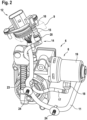
- Fig. 2 is a perspective view of the parking lock actuator 8 and the pressure compensation device 14. Furthermore, the connection device and a dashed section of the transmission housing 9 with the transmission housing opening 15 for the pressure compensation device 14 are shown.
- the pressure compensation device 14 comprises a feedthrough element 16, which passes through the gear housing opening 15, and a tubular fluid guide element 17, whose first (lower) end is connected to the interior of the parking lock actuator 8 and whose second (upper) end is connected to the feedthrough element 16.
- the pressure compensation device 14 has a first coupling 18, which engages with a - in Fig. 2 concealed, opposite coupling formed on a parking lock actuator housing 19.
- the pressure compensation device 14 has a second coupling 20, which is connected to the feedthrough element 16.
- the fluid guide element 17 is designed as a dimensionally stable tube that winds around the connecting device and is fastened to the cable arrangement 11 by means of a fastening means 23 arranged on the fluid guide element 17. Also visible are fastening means 24 of the connecting device attached to the cable arrangement 11, with which the connecting device is fastened within the transmission housing 9.
- Fig. 3 and Fig. 4 each show the feedthrough element 16, where Fig. 3 a sectioned view and Fig. 4 is a perspective view.
- the feedthrough element 16 has an elongated body 25.
- An inner cylindrical free space 27 extends along a longitudinal axis 26 of the body 25 and tapers conically towards an outer end of the body 25.
- the cylindrical free space 27 forms a feedthrough opening.
- the conical locking collar 22 is arranged on the outside of the lower free end of the body 25.
- a radially outwardly facing collar 29 of the body 25 is located on the outside of the gear housing 9 and forms a stop when inserting the feed-through element 16 into the gear housing opening 15.
- the feedthrough element 16 has a first row of projections 33 near its (lower) end.
- the first row comprises three projections 33 arranged equidistantly around the circumference.
- the feedthrough element 16 comprises two axially spaced rows of protruding projections 28 arranged in a circumferential direction.
- the two rows of projections 28 are referred to as the second and third row.
- Each projection 28 is approximately cuboid-shaped, with its longer side extending parallel to the longitudinal axis of the feedthrough element 16.
- the projections 28 have oblique, outwardly tapered side surfaces.
- the feedthrough element 16 has four projections 28 arranged in a circumferential direction.
- the projections 28 of the upper row are located at the same circumferential position as the projections 28 of the lower row.
- the projections of different rows are offset from one another in the circumferential direction.
- the projections 28 guide the feedthrough element 16 when it is inserted into the transmission housing opening 15 and form a press fit. This facilitates precise assembly of the feedthrough element 16.
- the projections 28 of the second and third rows are offset in the circumferential direction relative to the projections 33 of the first row.
- all projections are arranged at the same position in the circumferential direction.
- the free end of the feedthrough element 16, including the first row of projections 33 is located in the coupling 20 of the fluid guide element 17, which is designed as a cup coupling.
- the projections 33 center the feedthrough element 16 in the coupling 20 during insertion.
- the free end 21 of the feedthrough element 16 is so long that it is held positively in the coupling 20 of the fluid guide element 17.
- the feedthrough element 16 comprises a membrane 30 at its opposite end, which, when assembled, is located outside the gear housing 9.
- a gas-permeable protective cap 31 is located at the free end of the feedthrough element 16 or at the free end of the body 25.
- Two O-rings 32 coaxially surrounding the body 25 are arranged between the second and third row of projections 28 and seal the feedthrough element 16 from the gear housing opening 15.
- the feedthrough element 16 can be screwed into the housing opening 15.
- the feedthrough element 16 and the first connector 12 are guided through the same through-opening of the transmission.
- a flange section of the first connector can be expanded accordingly and penetrated by the feedthrough element 16.
- Fig. 5 to 7 are each sectional views and show an embodiment of a coupling arrangement with a feedthrough element 42 and a fluid guide element 40.
- Fig. 5 shows a section along the longitudinal direction
- Fig. 6 shows a section along the line VI-VI of Fig. 5
- Fig. 7 shows a section along the line VII-VII of Fig. 5 .
- the fluid guide element 40 and the feedthrough element 42 are in Fig. 5 shown schematically and slightly simplified, in particular the three rows of radially projecting projections of the feedthrough element 42 are shown in Fig. 5 not shown.
- the fluid guide element 40 has a cup-shaped recess 41 into which the feedthrough element 42 is inserted.
- Fig. 5 you can see that at At the bottom of the recess 41 is an O-ring 43, which rests with its outer side against the fluid conducting element 40 and with its inner side against the outer, free end 44 of the feedthrough element 42, thus sealing the intermediate space.
- the coupling arrangement comprises a fastening element for connecting the feedthrough element 42 and the fluid conducting element 40 to one another, wherein the fastening element comprises a deformable clip 10 that penetrates a lateral opening of the cup-shaped recess 41 of the fluid conducting element 40 and is inserted into a lateral recess of the feedthrough element 42.
- the clip 10 prevents the feedthrough element 42 from being pulled out of the fluid conducting element 40.
- the fastening element is deformable for clipping in and out and thus cannot adequately center the feedthrough element 42 on its own.
- the first row of projections 33 is arranged in front of the fastening element, i.e., above it, in the axial direction along which the feedthrough element 42 can be inserted into the fluid-conducting element 40.
- the radially inward-facing centering ribs 47 distributed along the inner circumference of the cup-shaped recess 41, are arranged behind the fastening element at a distal end 48 of the cup-shaped recess 41 in the axial direction along which the feedthrough element 42 can be inserted into the fluid-conducting element 40.
- the cutting plane of the Fig. 6 The view shown is located in the area of the projections 33.
- the feedthrough element 42 has the three radially outwardly projecting projections 33 there, which bear against the inside of the fluid guide element 40. These projections 33 guide the feedthrough element 42 during insertion into the fluid guide element 40 and center it.
- the cutting plane of the Fig. 7 shown view is located in the region of the lower, free end 44 of the feedthrough element 42 and near the distal end 48 of the cup-shaped recess 41 of the fluid guide element 40. It can be seen that the fluid guide element 40 has three distributed, radially inwardly pointing centering ribs 47 on its inner circumference, which centering ribs 47 bear against the outside of the free end 44 of the feedthrough element 42. These centering ribs 47 limit the existing play between the feedthrough element 42 and the fluid guide element 40. Since the feedthrough element 42 is supported at its lower, free end 44 by the centering ribs 47, tilting is prevented.
- Fig. 8 is a schematic diagram of a vehicle 34 with a drive device 35.
- the drive device 35 configured to drive the vehicle 34 comprises an electric machine 36, the transmission device 1, and a shaft configured to transmit torque from the electric machine 36 to the transmission device 1.
- the transmission housing 9 is configured as part of a housing 37 accommodating the electric machine 36, the shaft, and the transmission device 1.
- the drive device 35 has an inverter 38, which is designed to convert a direct voltage into an alternating voltage supplying the electric machine 36.
- the inverter 38 is connected by means of a cable 39 to the first connector 12 of the connection device (see Fig. 1 ) to electrically supply and control the parking lock actuator 8.
Landscapes
- Engineering & Computer Science (AREA)
- General Engineering & Computer Science (AREA)
- Mechanical Engineering (AREA)
- Power Engineering (AREA)
- Gear-Shifting Mechanisms (AREA)
- General Details Of Gearings (AREA)
- Quick-Acting Or Multi-Walled Pipe Joints (AREA)
Claims (9)
- Agencement d'accouplement, comprenant :- un élément de traversée (16, 42) pouvant être inséré dans une ouverture d'un boîtier pour former une communication fluidique entre l'extérieur et l'intérieur du boîtier,- un élément de guidage de fluide (17, 40) avec un évidement en forme de godet (41) dans lequel l'élément de traversée (16, 42) peut être inséré,l'élément de traversée (16, 42) présentant, à proximité de son extrémité orientée vers l'élément de guidage de fluide (17, 40), pour le centrage de l'élément de traversée (16, 42) dans l'élément de guidage de fluide (17, 40), une première rangée de saillies (33) dépassant radialement, agencées en étant réparties dans la direction périphérique,l'évidement en forme de godet (41) de l'élément de fluide (17, 40) présentant des nervures de centrage agencées en étant réparties sur sa périphérie intérieure, orientées radialement vers l'intérieur,- un élément de fixation pour relier l'élément de traversée (16, 42) et l'élément de guidage de fluide (17, 40) l'un à l'autre, l'élément de fixation comprenant un clip déformable (10) qui traverse une ouverture de l'évidement en forme de godet (41) et peut être inséré dans un évidement de l'élément de traversée (16, 42),la première rangée de saillies (33) étant agencée avant l'élément de fixation dans la direction axiale selon laquelle l'élément de traversée (16, 42) peut être inséré dans l'élément de guidage de fluide (17, 40), et les nervures de centrage (47) étant agencées après l'élément de fixation dans la direction axiale selon laquelle l'élément de traversée (16, 42) peut être inséré dans l'élément de guidage de fluide (17, 40).
- Agencement d'accouplement selon la revendication 1, les nervures de centrage (47) étant agencées à une extrémité distale (48) de l'évidement en forme de godet (41).
- Agencement d'accouplement selon l'une quelconque des revendications précédentes, la première rangée de saillies (33) de l'élément de traversée (16, 42) présentant trois saillies (33) agencées en étant réparties dans la direction périphérique.
- Agencement d'accouplement selon l'une quelconque des revendications précédentes, l'élément de traversée (16, 42) présentant deux autres rangées espacées axialement de saillies (28) dépassant radialement, agencées en étant réparties dans la direction périphérique, pour centrer l'élément de traversée (16, 42) dans l'ouverture du boîtier.
- Agencement d'accouplement selon la revendication 4, les deuxième et troisième rangées de saillies (28) présentant chacune quatre saillies (28) agencées en étant réparties dans la direction périphérique.
- Agencement d'accouplement selon la revendication 4 ou 5, un joint torique (32) étant agencement axialement avant et après chacune des deux rangées de saillies (28).
- Agencement d'accouplement selon l'une quelconque des revendications 4 à 6, les saillies (28, 33) de la première et/ou de la deuxième et/ou de la troisième rangée s'étendant dans la direction axiale de l'élément de traversée (16, 42) et étant réalisées sous forme essentiellement parallélépipédique.
- Agencement d'accouplement selon l'une quelconque des revendications précédentes, les saillies (28, 33) de la première et/ou de la deuxième et/ou de la troisième rangée présentant des surfaces latérales inclinées se rétrécissant radialement vers l'extérieur.
- Dispositif de transmission (1) pour un véhicule à propulsion électrique, comprenant :- une roue de verrouillage de stationnement (5),- un verrou de stationnement (6) avec un actionneur de verrouillage de stationnement (8) pour bloquer la roue de verrouillage de stationnement (5),- un boîtier de transmission (9) dans lequel sont reçus la roue de verrouillage de stationnement (5) et le verrou de stationnement (6),- un dispositif d'équilibrage de pression (14) par lequel l'intérieur de l'actionneur de verrouillage de stationnement (8) est en communication fluidique avec l'extérieur du boîtier de transmission (9), le dispositif d'équilibrage de pression (14) présentant un agencement d'accouplement selon l'une quelconque des revendications 1 à 8, dont l'élément de traversée (16, 42) traverse le boîtier de transmission (9) et dont l'élément de guidage de fluide (17, 40) est relié à l'intérieur de l'actionneur de verrouillage de stationnement (8).
Priority Applications (5)
| Application Number | Priority Date | Filing Date | Title |
|---|---|---|---|
| EP22170122.0A EP4269837B1 (fr) | 2022-04-26 | 2022-04-26 | Agencement d'accouplement et dispositif de transmission doté d'un tel agencement d'accouplement |
| KR1020247035546A KR20240161692A (ko) | 2022-04-26 | 2023-04-21 | 커플링 장치, 및 커플링 장치를 갖는 전동 장치 |
| JP2024563456A JP2025514251A (ja) | 2022-04-26 | 2023-04-21 | 継手構成およびそのような継手構成を有する変速機装置 |
| PCT/EP2023/060531 WO2023208785A1 (fr) | 2022-04-26 | 2023-04-21 | Ensemble d'accouplement, et dispositif de transmission doté d'un ensemble d'accouplement de ce type |
| CN202380040802.2A CN119234101A (zh) | 2022-04-26 | 2023-04-21 | 联接组件,以及带有该类型联接组件的传动设备 |
Applications Claiming Priority (1)
| Application Number | Priority Date | Filing Date | Title |
|---|---|---|---|
| EP22170122.0A EP4269837B1 (fr) | 2022-04-26 | 2022-04-26 | Agencement d'accouplement et dispositif de transmission doté d'un tel agencement d'accouplement |
Publications (2)
| Publication Number | Publication Date |
|---|---|
| EP4269837A1 EP4269837A1 (fr) | 2023-11-01 |
| EP4269837B1 true EP4269837B1 (fr) | 2025-04-30 |
Family
ID=81387144
Family Applications (1)
| Application Number | Title | Priority Date | Filing Date |
|---|---|---|---|
| EP22170122.0A Active EP4269837B1 (fr) | 2022-04-26 | 2022-04-26 | Agencement d'accouplement et dispositif de transmission doté d'un tel agencement d'accouplement |
Country Status (5)
| Country | Link |
|---|---|
| EP (1) | EP4269837B1 (fr) |
| JP (1) | JP2025514251A (fr) |
| KR (1) | KR20240161692A (fr) |
| CN (1) | CN119234101A (fr) |
| WO (1) | WO2023208785A1 (fr) |
Family Cites Families (7)
| Publication number | Priority date | Publication date | Assignee | Title |
|---|---|---|---|---|
| DE9016310U1 (de) * | 1990-11-30 | 1991-02-21 | Hewing GmbH, 4434 Ochtrup | Rohrverbindung, insbesondere an Verbundrohren |
| EP0511891B1 (fr) * | 1991-04-29 | 1995-03-15 | Etablissements CAILLAU | Elément de connexion pour le raccordement rapide d'un tube |
| US20030057699A1 (en) * | 2001-09-27 | 2003-03-27 | Persohn Matthew M. | Coupling assembly with rotation lock |
| JP4264324B2 (ja) * | 2003-10-16 | 2009-05-13 | 株式会社パイオラックス | 接続構造或いは締結構造 |
| US20100052315A1 (en) * | 2008-08-28 | 2010-03-04 | Ti Group Automotive Systems, Llc | Quick connector coupling with lateral stabilization |
| DE102018133266A1 (de) | 2018-12-20 | 2020-06-25 | Fte Automotive Gmbh | Getriebegehäuse mit elektromechanischem Parksperrenaktuator |
| DE102019132496A1 (de) * | 2019-11-29 | 2021-06-02 | Valeo Siemens Eautomotive Germany Gmbh | Getriebeeinrichtung für ein elektrisch antreibbares Fahrzeug, Antriebseinrichtung für ein elektrisch antreibbares Fahrzeug und Fahrzeug |
-
2022
- 2022-04-26 EP EP22170122.0A patent/EP4269837B1/fr active Active
-
2023
- 2023-04-21 JP JP2024563456A patent/JP2025514251A/ja active Pending
- 2023-04-21 WO PCT/EP2023/060531 patent/WO2023208785A1/fr not_active Ceased
- 2023-04-21 CN CN202380040802.2A patent/CN119234101A/zh active Pending
- 2023-04-21 KR KR1020247035546A patent/KR20240161692A/ko active Pending
Also Published As
| Publication number | Publication date |
|---|---|
| JP2025514251A (ja) | 2025-05-02 |
| WO2023208785A1 (fr) | 2023-11-02 |
| EP4269837A1 (fr) | 2023-11-01 |
| KR20240161692A (ko) | 2024-11-12 |
| CN119234101A (zh) | 2024-12-31 |
Similar Documents
| Publication | Publication Date | Title |
|---|---|---|
| DE69426652T2 (de) | Schnellkupplungsgehäuse mit einer ausgestreckten rippe | |
| EP0906534B1 (fr) | Connecteur amovible avec indicateur de montage | |
| DE102006062894B4 (de) | Schutzkappe | |
| DE102017115046A1 (de) | Dauerhafter schnellverbinder samt zugehöriger anordnung | |
| DE102011118099A1 (de) | Vorrichtung zum Verbinden zweier Leitungsabschnitte | |
| DE10343729A1 (de) | Rohrverbinder | |
| DE102009057867A1 (de) | Kupplungseinrichtung und Frischluftanlage | |
| AT525758B1 (de) | Steckverbinder zum Verbinden von Leitungen für flüssige oder gasförmige Medien | |
| EP1150056B1 (fr) | Dispositif de raccordement pour un tuyau en plastique | |
| EP1653141A1 (fr) | Dispositif de connection et dispositif de filtrage avec un tel dispositif de connection | |
| DE69507100T2 (de) | Verschlussstopfen für eine Schnellverbindung | |
| DE102016001610A1 (de) | Einsteckkupplung | |
| EP4269837B1 (fr) | Agencement d'accouplement et dispositif de transmission doté d'un tel agencement d'accouplement | |
| EP0545037A1 (fr) | Dispositif d'accouplement de deux conduites, en particulier pour des conduites de carburant | |
| EP2133615B2 (fr) | Installation d'air frais et dispositif de couplage | |
| DE102007037531A1 (de) | Anordnung von benachbarten Planetenradsätzen in einem Getriebe | |
| DE3104518A1 (de) | Anschlussarmatur | |
| EP0579141A1 (fr) | Montage automatique d'un accouplement enfichable pour tuyaux flexibles dans des véhicules automobiles | |
| DE19736765A1 (de) | Einsteckkupplung | |
| EP0205823A2 (fr) | Raccord à action rapide pour tuyaux ou similaires | |
| EP3012502B1 (fr) | Dispositif de raccordement pour un tuyau et tuyau avec un tel dispositif | |
| EP4249784A1 (fr) | Adaptateur de tuyau | |
| DE4022769C2 (de) | Rohrleitungsmehrfachkupplung | |
| DE102019100978B3 (de) | Vorrichtung zum Synchronisieren und/oder Schalten in einem Getriebegehäuse und Getriebe | |
| EP3626898B1 (fr) | Système de tubes profilés |
Legal Events
| Date | Code | Title | Description |
|---|---|---|---|
| PUAI | Public reference made under article 153(3) epc to a published international application that has entered the european phase |
Free format text: ORIGINAL CODE: 0009012 |
|
| STAA | Information on the status of an ep patent application or granted ep patent |
Free format text: STATUS: THE APPLICATION HAS BEEN PUBLISHED |
|
| AK | Designated contracting states |
Kind code of ref document: A1 Designated state(s): AL AT BE BG CH CY CZ DE DK EE ES FI FR GB GR HR HU IE IS IT LI LT LU LV MC MK MT NL NO PL PT RO RS SE SI SK SM TR |
|
| STAA | Information on the status of an ep patent application or granted ep patent |
Free format text: STATUS: REQUEST FOR EXAMINATION WAS MADE |
|
| 17P | Request for examination filed |
Effective date: 20240502 |
|
| RBV | Designated contracting states (corrected) |
Designated state(s): AL AT BE BG CH CY CZ DE DK EE ES FI FR GB GR HR HU IE IS IT LI LT LU LV MC MK MT NL NO PL PT RO RS SE SI SK SM TR |
|
| GRAP | Despatch of communication of intention to grant a patent |
Free format text: ORIGINAL CODE: EPIDOSNIGR1 |
|
| STAA | Information on the status of an ep patent application or granted ep patent |
Free format text: STATUS: GRANT OF PATENT IS INTENDED |
|
| RIC1 | Information provided on ipc code assigned before grant |
Ipc: F16H 63/34 20060101ALN20241111BHEP Ipc: H02K 7/116 20060101ALI20241111BHEP Ipc: F16H 57/02 20120101ALI20241111BHEP Ipc: F16L 37/088 20060101ALI20241111BHEP Ipc: F16L 5/10 20060101ALI20241111BHEP Ipc: F16H 57/027 20120101AFI20241111BHEP |
|
| INTG | Intention to grant announced |
Effective date: 20241126 |
|
| RIN1 | Information on inventor provided before grant (corrected) |
Inventor name: RUCIN SKA, JOANNA Inventor name: FUERSTENHOEFER, CHRISTIAN Inventor name: HAAS, BERND |
|
| GRAS | Grant fee paid |
Free format text: ORIGINAL CODE: EPIDOSNIGR3 |
|
| GRAA | (expected) grant |
Free format text: ORIGINAL CODE: 0009210 |
|
| STAA | Information on the status of an ep patent application or granted ep patent |
Free format text: STATUS: THE PATENT HAS BEEN GRANTED |
|
| AK | Designated contracting states |
Kind code of ref document: B1 Designated state(s): AL AT BE BG CH CY CZ DE DK EE ES FI FR GB GR HR HU IE IS IT LI LT LU LV MC MK MT NL NO PL PT RO RS SE SI SK SM TR |
|
| REG | Reference to a national code |
Ref country code: CH Ref legal event code: EP Ref country code: GB Ref legal event code: FG4D Free format text: NOT ENGLISH |
|
| REG | Reference to a national code |
Ref country code: IE Ref legal event code: FG4D Free format text: LANGUAGE OF EP DOCUMENT: GERMAN |
|
| REG | Reference to a national code |
Ref country code: DE Ref legal event code: R096 Ref document number: 502022003727 Country of ref document: DE |
|
| REG | Reference to a national code |
Ref country code: NL Ref legal event code: MP Effective date: 20250430 |
|
| PG25 | Lapsed in a contracting state [announced via postgrant information from national office to epo] |
Ref country code: FI Free format text: LAPSE BECAUSE OF FAILURE TO SUBMIT A TRANSLATION OF THE DESCRIPTION OR TO PAY THE FEE WITHIN THE PRESCRIBED TIME-LIMIT Effective date: 20250430 Ref country code: ES Free format text: LAPSE BECAUSE OF FAILURE TO SUBMIT A TRANSLATION OF THE DESCRIPTION OR TO PAY THE FEE WITHIN THE PRESCRIBED TIME-LIMIT Effective date: 20250430 Ref country code: PT Free format text: LAPSE BECAUSE OF FAILURE TO SUBMIT A TRANSLATION OF THE DESCRIPTION OR TO PAY THE FEE WITHIN THE PRESCRIBED TIME-LIMIT Effective date: 20250901 |
|
| REG | Reference to a national code |
Ref country code: LT Ref legal event code: MG9D |
|
| PG25 | Lapsed in a contracting state [announced via postgrant information from national office to epo] |
Ref country code: GR Free format text: LAPSE BECAUSE OF FAILURE TO SUBMIT A TRANSLATION OF THE DESCRIPTION OR TO PAY THE FEE WITHIN THE PRESCRIBED TIME-LIMIT Effective date: 20250731 Ref country code: NO Free format text: LAPSE BECAUSE OF FAILURE TO SUBMIT A TRANSLATION OF THE DESCRIPTION OR TO PAY THE FEE WITHIN THE PRESCRIBED TIME-LIMIT Effective date: 20250730 |
|
| PG25 | Lapsed in a contracting state [announced via postgrant information from national office to epo] |
Ref country code: PL Free format text: LAPSE BECAUSE OF FAILURE TO SUBMIT A TRANSLATION OF THE DESCRIPTION OR TO PAY THE FEE WITHIN THE PRESCRIBED TIME-LIMIT Effective date: 20250430 Ref country code: NL Free format text: LAPSE BECAUSE OF FAILURE TO SUBMIT A TRANSLATION OF THE DESCRIPTION OR TO PAY THE FEE WITHIN THE PRESCRIBED TIME-LIMIT Effective date: 20250430 |
|
| PG25 | Lapsed in a contracting state [announced via postgrant information from national office to epo] |
Ref country code: BG Free format text: LAPSE BECAUSE OF FAILURE TO SUBMIT A TRANSLATION OF THE DESCRIPTION OR TO PAY THE FEE WITHIN THE PRESCRIBED TIME-LIMIT Effective date: 20250430 |
|
| PG25 | Lapsed in a contracting state [announced via postgrant information from national office to epo] |
Ref country code: HR Free format text: LAPSE BECAUSE OF FAILURE TO SUBMIT A TRANSLATION OF THE DESCRIPTION OR TO PAY THE FEE WITHIN THE PRESCRIBED TIME-LIMIT Effective date: 20250430 |
|
| PG25 | Lapsed in a contracting state [announced via postgrant information from national office to epo] |
Ref country code: RS Free format text: LAPSE BECAUSE OF FAILURE TO SUBMIT A TRANSLATION OF THE DESCRIPTION OR TO PAY THE FEE WITHIN THE PRESCRIBED TIME-LIMIT Effective date: 20250731 |
|
| PG25 | Lapsed in a contracting state [announced via postgrant information from national office to epo] |
Ref country code: IS Free format text: LAPSE BECAUSE OF FAILURE TO SUBMIT A TRANSLATION OF THE DESCRIPTION OR TO PAY THE FEE WITHIN THE PRESCRIBED TIME-LIMIT Effective date: 20250830 |
|
| PG25 | Lapsed in a contracting state [announced via postgrant information from national office to epo] |
Ref country code: LV Free format text: LAPSE BECAUSE OF FAILURE TO SUBMIT A TRANSLATION OF THE DESCRIPTION OR TO PAY THE FEE WITHIN THE PRESCRIBED TIME-LIMIT Effective date: 20250430 |
|
| PG25 | Lapsed in a contracting state [announced via postgrant information from national office to epo] |
Ref country code: SM Free format text: LAPSE BECAUSE OF FAILURE TO SUBMIT A TRANSLATION OF THE DESCRIPTION OR TO PAY THE FEE WITHIN THE PRESCRIBED TIME-LIMIT Effective date: 20250430 Ref country code: DK Free format text: LAPSE BECAUSE OF FAILURE TO SUBMIT A TRANSLATION OF THE DESCRIPTION OR TO PAY THE FEE WITHIN THE PRESCRIBED TIME-LIMIT Effective date: 20250430 |
|
| PG25 | Lapsed in a contracting state [announced via postgrant information from national office to epo] |
Ref country code: CZ Free format text: LAPSE BECAUSE OF FAILURE TO SUBMIT A TRANSLATION OF THE DESCRIPTION OR TO PAY THE FEE WITHIN THE PRESCRIBED TIME-LIMIT Effective date: 20250430 |
|
| PG25 | Lapsed in a contracting state [announced via postgrant information from national office to epo] |
Ref country code: EE Free format text: LAPSE BECAUSE OF FAILURE TO SUBMIT A TRANSLATION OF THE DESCRIPTION OR TO PAY THE FEE WITHIN THE PRESCRIBED TIME-LIMIT Effective date: 20250430 |
|
| PG25 | Lapsed in a contracting state [announced via postgrant information from national office to epo] |
Ref country code: SK Free format text: LAPSE BECAUSE OF FAILURE TO SUBMIT A TRANSLATION OF THE DESCRIPTION OR TO PAY THE FEE WITHIN THE PRESCRIBED TIME-LIMIT Effective date: 20250430 |
|
| PG25 | Lapsed in a contracting state [announced via postgrant information from national office to epo] |
Ref country code: IT Free format text: LAPSE BECAUSE OF FAILURE TO SUBMIT A TRANSLATION OF THE DESCRIPTION OR TO PAY THE FEE WITHIN THE PRESCRIBED TIME-LIMIT Effective date: 20250430 |
|
| REG | Reference to a national code |
Ref country code: DE Ref legal event code: R097 Ref document number: 502022003727 Country of ref document: DE |
|
| PLBE | No opposition filed within time limit |
Free format text: ORIGINAL CODE: 0009261 |
|
| STAA | Information on the status of an ep patent application or granted ep patent |
Free format text: STATUS: NO OPPOSITION FILED WITHIN TIME LIMIT |
|
| REG | Reference to a national code |
Ref country code: CH Ref legal event code: L10 Free format text: ST27 STATUS EVENT CODE: U-0-0-L10-L00 (AS PROVIDED BY THE NATIONAL OFFICE) Effective date: 20260311 |
|
| 26N | No opposition filed |
Effective date: 20260202 |