EP4270681A1 - Connecteur de barre conductrice - Google Patents
Connecteur de barre conductrice Download PDFInfo
- Publication number
- EP4270681A1 EP4270681A1 EP23168530.6A EP23168530A EP4270681A1 EP 4270681 A1 EP4270681 A1 EP 4270681A1 EP 23168530 A EP23168530 A EP 23168530A EP 4270681 A1 EP4270681 A1 EP 4270681A1
- Authority
- EP
- European Patent Office
- Prior art keywords
- housing
- plug contact
- contact sections
- current
- busbar connector
- Prior art date
- Legal status (The legal status is an assumption and is not a legal conclusion. Google has not performed a legal analysis and makes no representation as to the accuracy of the status listed.)
- Granted
Links
Images




Classifications
-
- H—ELECTRICITY
- H01—ELECTRIC ELEMENTS
- H01R—ELECTRICALLY-CONDUCTIVE CONNECTIONS; STRUCTURAL ASSOCIATIONS OF A PLURALITY OF MUTUALLY-INSULATED ELECTRICAL CONNECTING ELEMENTS; COUPLING DEVICES; CURRENT COLLECTORS
- H01R25/00—Coupling parts adapted for simultaneous co-operation with two or more identical counterparts, e.g. for distributing energy to two or more circuits
- H01R25/14—Rails or bus-bars constructed so that the counterparts can be connected thereto at any point along their length
- H01R25/145—Details, e.g. end pieces or joints
-
- H—ELECTRICITY
- H01—ELECTRIC ELEMENTS
- H01R—ELECTRICALLY-CONDUCTIVE CONNECTIONS; STRUCTURAL ASSOCIATIONS OF A PLURALITY OF MUTUALLY-INSULATED ELECTRICAL CONNECTING ELEMENTS; COUPLING DEVICES; CURRENT COLLECTORS
- H01R13/00—Details of coupling devices of the kinds covered by groups H01R12/70 or H01R24/00 - H01R33/00
- H01R13/02—Contact members
-
- H—ELECTRICITY
- H01—ELECTRIC ELEMENTS
- H01R—ELECTRICALLY-CONDUCTIVE CONNECTIONS; STRUCTURAL ASSOCIATIONS OF A PLURALITY OF MUTUALLY-INSULATED ELECTRICAL CONNECTING ELEMENTS; COUPLING DEVICES; CURRENT COLLECTORS
- H01R13/00—Details of coupling devices of the kinds covered by groups H01R12/70 or H01R24/00 - H01R33/00
- H01R13/62—Means for facilitating engagement or disengagement of coupling parts or for holding them in engagement
- H01R13/639—Additional means for holding or locking coupling parts together, after engagement, e.g. separate keylock, retainer strap
-
- H—ELECTRICITY
- H01—ELECTRIC ELEMENTS
- H01R—ELECTRICALLY-CONDUCTIVE CONNECTIONS; STRUCTURAL ASSOCIATIONS OF A PLURALITY OF MUTUALLY-INSULATED ELECTRICAL CONNECTING ELEMENTS; COUPLING DEVICES; CURRENT COLLECTORS
- H01R31/00—Coupling parts supported only by co-operation with counterpart
- H01R31/06—Intermediate parts for linking two coupling parts, e.g. adapter
Definitions
- the invention relates to a busbar connector with a housing, the housing being set up for the mechanical coupling of two current-carrying profiles, the power-carrying profiles each having grooves arranged next to one another for receiving electrical conductors and the grooves extending in a longitudinal direction of the respective power-carrying profile, and with at least one electrical connector accommodated in the housing, wherein the electrical connector has at least two plug-in contact sections with conductor contacts, the plug-in contact sections each being set up for electrically contacting associated electrical conductors of one of the current-carrying profiles in an operating position.
- DE 10 2011 114 160 B4 discloses a mounting rail profile for a lighting arrangement with a modular current-carrying profile, the power-carrying profile having two power-carrying profile elements.
- the current-carrying profile elements are individually connected to the mounting rail profile or are connected to one another in a form-fitting manner.
- DE 10 2010 032 383 A3 discloses a busbar connector for connecting two power management profiles.
- the busbar connector has two plug-in contact sections for contacting a current-carrying profile, whereby the busbar connector can be plugged onto the power-carrying profile in order to make electrically conductive contact with the electrical conductors accommodated in the grooves with the plug-in contact sections.
- At least one of the plug contact sections is mounted in the housing so as to be displaceable in the longitudinal direction of the current-carrying profile in the operating position.
- the operating position is in particular the position in which the plug contact sections make electrical contact with the associated electrical conductors of the respective current-carrying profiles when the busbar connector is already mechanically connected to two power-carrying profiles.
- the electrical contacts of the electrical connector are firmly connected to the electrical lines.
- This connection is basically achieved by the cutting edges of the electrical contacts digging into the electrical conductors accommodated in the grooves.
- a longitudinal expansion of the current-carrying profile such as occurs for example due to a change in temperature, is transmitted directly to the electrical connectors in the operating position.
- the plug contact sections of the electrical connector can be mounted in the housing in the operating position so as to be displaceable in the longitudinal direction of the current-carrying profile.
- the plug contact sections can each be mounted on one of the diametrically opposite ends or end sections of the housing, the plug contact sections being arranged at least at a distance from one another in the housing in the longitudinal direction of the busbar connector and being connected to one another via further electrical conductors.
- the further electrical conductors can in particular be designed to be flexible. In this way, a flexible busbar connector can be provided which can easily accommodate or compensate for a length compensation in the longitudinal direction of the current-carrying profile, whereby the functionality of the busbar connector can be further improved.
- a large number of electrical connectors can be accommodated in parallel in the housing, with one electrical connector each being set up for electrically contacting two current-carrying profiles. It has been shown that it is advantageous if two electrical connectors in particular are accommodated in parallel in the housing.
- the large number of electrical connectors is set up for electrical contacting of exactly two current-carrying profiles or that one electrical connector connects two different current-carrying profiles to one another in an electrically conductive manner.
- At least one of the conductor contacts can be designed as a crimp contact.
- a PE contact of the plug contact sections can be designed as a crimp contact. This creates a difficult-to-detach connection between the conductor and the connecting element, which ensures a high level of electrical and mechanical safety.
- a guide element for displaceably guiding the plug contact sections in the housing of the busbar connector can be arranged perpendicular to the longitudinal direction of the current carrying profile.
- the guide element can be designed as at least one guide rail, wherein the guide rail can be guided in a corresponding guide groove of the housing.
- the guide rail can be L-shaped or T-shaped in cross section.
- the rail/groove guide ensures reliable guidance of the plug contact sections through simple and constructive measures.
- the guide rail can in particular have a web projecting from the respective plug contact section, a wing-like guide plate or a wing-like guide section being arranged on the web parallel to the plug contact section, which is spaced from the plug contact section by the web.
- the guide plate or the guide section can engage behind the guide groove of the housing, with the web being guided through the guide groove. Since the wing-like guide plate or the wing-like guide section is designed to be larger than the guide groove, the respective plug contact section can be easily guided in or along the guide groove.
- the housing itself is made of sheet steel.
- the corresponding guide groove can be designed in such a way that at least the plug contact sections are mounted in the housing so as to be displaceable in the longitudinal direction of the current-carrying profile in the operating position.
- the plug contact sections can be mounted displaceably from a pre-locking position to the operating position within the guide groove.
- the pre-locking position is in particular the position in which the plug contact sections cannot yet be electrically connected to the electrical conductors of the current-carrying profiles when the busbar connector is already mechanically connected to two power-carrying profiles.
- the mechanical connection of the busbar connector to the current-carrying profiles can be decoupled from the electrical connection of the electrical conductors accommodated in the grooves of the current-carrying profiles.
- the mechanical connection is therefore independent of the electrical connection.
- busbar connector can be manufactured and delivered in the pre-locking position of the plug-in contact sections, so that the user only has to move the plug-in contact sections into the power-carrying profiles after installing the busbar connector.
- the guide groove can be designed in the area of the pre-locking position as a guide groove adapted to the guide rail, so that in the pre-locking position, longitudinal displaceability of the plug contact sections in the longitudinal direction of the current-carrying profiles is blocked.
- the guide groove in the area of the pre-locking position can advantageously be arranged in particular centrally to the wider guide groove in the area of the operating position. This ensures that the plug contact section can be moved in a uniform, possible longitudinal manner in the operating position.
- a locking element can be arranged on each of the plug contact sections to secure the plug contact sections in the operating position and/or the pre-locking position. Furthermore, the locking element can advantageously be designed as a locking pawl, for example.
- a latching pawl can in particular be designed to be resilient, with the latching pawl working against you when the plug contact section is transferred into the operating position Spring force is bent and returns to its starting position after reaching the operating position, with a locking projection of the locking pawl preventing the plug contact section from being accidentally released from the operating position.
- the locking element can be accommodated in a corresponding recess in the housing in the operating position and/or in the pre-locking position, the recess being designed to be so wide that the locking element is mounted displaceably in the operating position in the longitudinal direction of the current-carrying profiles.
- the recess is designed to be so large that the locking element in the recess has enough play to ensure longitudinal displacement.
- the corresponding recess in the housing for the locking element can in particular be arranged between two guide grooves, which are each designed to accommodate a guide rail.
- the locking element can also be arranged between two guide elements, in particular two guide rails.
- the wall of the housing can be exposed to the outside with the corresponding recesses. This means that this wall is exposed to the plane of the housing. In this way, sufficient space can be provided for the locking element.
- the invention relates to a busbar system with at least two adjacent current-carrying profiles, each of which has grooves open on one side and extends in the longitudinal direction of the busbars, with electrical conductors accommodated in the grooves being arranged, and with at least one busbar connector described above.
- indefinite term “a” is to be understood as such and not as a numeral. It is also conceivable that several electrical connectors are arranged in the housing.
- Figure 1a shows a busbar system 13 according to the invention in a perspective view, where Figure 1b the busbar system according to the invention Figure 1a shows in a side view.
- the busbar system 13 has a busbar connector 1 with a housing 2, the housing 2 for the mechanical coupling of two Current management profiles 3 are set up.
- the current-carrying profiles 3 each have grooves 4 arranged next to one another, electrical conductors 5 being accommodated in the grooves 4.
- the grooves 4 extend in a longitudinal direction L of the respective current-carrying profile 3.
- An electrical connector 6 is arranged in the housing 2, the electrical connector 6 each having a plug contact section 7 at diametrically opposite ends.
- Conductor contacts 8 are arranged on the plug-in contact sections 7, the plug-in contact sections 7 being set up via the conductor contacts 8 for electrical contacting of associated electrical conductors 5, each of one of the current-carrying profiles 3.
- the position in which the plug contact sections 7 make electrical contact with the associated electrical conductors 5 of the respective current-carrying profiles 3 is also referred to below as operating position B.
- Figure 2a shows the busbar system 13 according to the invention according to the Figures 1a and 1b in a perspective view with only one current-carrying profile 3, whereby the functionality of the busbar connector 1 can be explained in more detail.
- Figure 2b shows the busbar system 13 according to the Figure 2a in a side view with a plug contact section 7 in an operating position B and a plug contact section 7 in a pre-locking position V.
- guide grooves 2a are arranged in the housing 2 of the busbar connector 1, with associated guide elements 10 of the busbar connector 1 engaging in these guide grooves 2a.
- the respective plug contact sections 7 of the electrical connectors 6 can be guided perpendicular to the longitudinal extension direction L of the busbar connector.
- There is no exact vertical Leadership required. Deviations of 10 degrees from a 90 degree alignment of the guide elements 10 to the longitudinal direction of the busbar connector 1 are also conceivable.
- the respective plug contact sections 6 can be easily displaced, in particular shifted, from the pre-locking position V into the operating position B by the guide elements 10. A reverse guidance from the operating position B into the pre-locking position is also conceivable.
- the pre-locking position V is in particular the position of the respective plug-in contact sections 6, in which the plug-in contact sections 6 cannot yet be electrically connected to the electrical conductors 5 of the current-carrying profiles 3.
- the busbar connector 3 is already mechanically connected to the current-carrying profiles 3.
- At least one locking element 11 is arranged on the plug contact sections 6, the locking element 11 being designed to lock with the housing 2. The locking can take place both in the operating position B and in the pre-locking position V.
- the locking element can lock with the housing 2 in a corresponding recess 12 both in the operating position B and in the pre-locking position V.
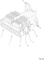
- Figure 3a shows two parallel electrical connectors 6 for a busbar connector 1, for example in the Figures 1 to 2b can be recognized.
- a plug contact section 7 is arranged at the diametrically opposite ends of each electrical connector 6, the plug contact sections 7 having conductor contacts 8 which are set up for electrically conductive contacting of the electrical conductors of the current-carrying profiles received in the grooves.
- the diametrically opposed plug contact sections 7 are connected to one another via further flexible electrical conductors 14.
- the guide elements 10 are designed as guide rails.
- the guide elements 10 are T-shaped.
- the guide elements 10 or the guide rails can in particular have a web projecting from the respective plug contact section 7, a wing-like guide plate or a wing-like guide section being arranged on the web parallel to the plug contact section 7, which is spaced from the plug contact section 7 by the web.
- the guide plate or the The guide section can engage behind the guide groove 2a of the housing 2, with the web being guided through the guide groove 2a. Since the wing-like guide plate or the wing-like guide section is designed to be larger than the guide groove 2a, the respective plug contact section 7 can be guided in or along the guide groove in a simple manner.
- Each plug contact section 7 can have two guide elements 10, or guide rails, which can dip into or engage behind a corresponding guide groove 2a of the housing 2.
- the locking element 11 can be arranged between the guide elements 10 in order to lock the respective plug contact section 7 with the housing 2 in the pre-locking position or the operating position of the plug connector.
- the guide elements 10 and the locking elements 11 are arranged on an outside 7a of each plug contact section 7.
- FIG 3b shows an enlarged section of the plug contact sections 7 of the electrical connectors 6 according to the Figure 3a . From the Figure 3b The design of the respective plug contact sections 7 is shown in more detail. It becomes clear that the guide elements 10 are particularly T-shaped in order to enable reliable guidance of the respective plug contact section 7 in the housing 2. The plug contact sections 7 can then be locked via the respective locking element 11 with the housing 2 of the busbar connector 1 in the pre-locking position V or in the operating position.
- Figure 4a shows the connection interface between the electrical connector 6 and housing 2.
- Figure 4b shows the connection interface Figure 4a between the electrical connector 6 and the housing 2, the electrical connector 6 compared to Figure 4a is shifted in the longitudinal direction L of the busbar connector 1, or the current-carrying profiles.
- the plug contact sections 7 are located in the Figure 4a and 4b in the operating position B. This means that the conductor contacts 8 of the respective plug contact section 7 contact the electrical conductors 5 accommodated in the grooves 4 in an electrically conductive manner.
- the plug contact sections 7 are mounted displaceably in the housing 2 in the operating position B in the longitudinal direction L of the current-carrying profile 3 or the busbar connector 1.
- the displaceability of the plug contact sections 7 is achieved in this exemplary embodiment in that the guide elements 10 are displaceably mounted in the guide grooves 2a of the housing 2 in the operating position, so that a movement of the plug contact sections 7 in the longitudinal direction L can be achieved.
- the guide grooves 2a are wider in the longitudinal direction L than the guide elements 10 accommodated in the guide grooves 2a, or the web of the guide rail, so that the plug contact sections 7 within the wider guide groove 2a in the operating position B in the longitudinal direction L of the current-carrying profiles 3 in the housing 2 are slidably mounted because there is enough play for the guide rail or the guide element 10.
- the locking element 11 arranged between the two guide elements 10 is locked to the housing 2 in one of the corresponding recesses 12, so that displacement of the plug contact sections 7 from the operating position B is blocked.
- the recess 12 is dimensioned correspondingly large, so that the locking element 11 can also move in the recess along the longitudinal extension direction 3 of the busbar connector 1 or the current-carrying profiles 3, so that the longitudinal displaceability of the respective plug contact sections 7 remains guaranteed without releasing the latching.
- the width of the guide grooves 2a is smaller than the width of the guide grooves 2a in the area of the operating position B.
- the guide grooves 2a are thus in the area of the pre-locking position V as one on the guide rail or the guide element 10 , customized Guide groove 2a is formed, so that a longitudinal displaceability L of the plug contact sections 7 in the longitudinal direction L of the current-carrying profiles 3, or of the busbar connector 1, is blocked.
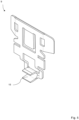
- Figure 5 shows a crimp contact 9, which is designed in particular as a PE contact of the plug contact sections 7.
- a protective earth line can be reliably contacted in an electrically conductive manner through the crimp contact 9.
- the crimp contact 9 has a crimp area 15, an electrical conductor in this crimp area 15 being able to be connected in a form-fitting manner using a crimping tool.
Landscapes
- Connector Housings Or Holding Contact Members (AREA)
Applications Claiming Priority (1)
| Application Number | Priority Date | Filing Date | Title |
|---|---|---|---|
| DE102022110373.0A DE102022110373B4 (de) | 2022-04-28 | 2022-04-28 | Stromschienenverbinder und Stromschienensystem |
Publications (2)
| Publication Number | Publication Date |
|---|---|
| EP4270681A1 true EP4270681A1 (fr) | 2023-11-01 |
| EP4270681B1 EP4270681B1 (fr) | 2025-12-17 |
Family
ID=86053574
Family Applications (1)
| Application Number | Title | Priority Date | Filing Date |
|---|---|---|---|
| EP23168530.6A Active EP4270681B1 (fr) | 2022-04-28 | 2023-04-18 | Connecteur de barre conductrice |
Country Status (3)
| Country | Link |
|---|---|
| EP (1) | EP4270681B1 (fr) |
| CN (1) | CN116979321A (fr) |
| DE (1) | DE102022110373B4 (fr) |
Families Citing this family (1)
| Publication number | Priority date | Publication date | Assignee | Title |
|---|---|---|---|---|
| CN118693573B (zh) * | 2024-07-02 | 2024-12-27 | 扬州森源电力科技有限公司 | 一种带有定位结构的防脱落母线连接器组件 |
Citations (3)
| Publication number | Priority date | Publication date | Assignee | Title |
|---|---|---|---|---|
| US20030021111A1 (en) * | 2001-07-30 | 2003-01-30 | Miller Jack V. | Multi-circuit tracklight system |
| DE102011114160B4 (de) | 2011-09-23 | 2013-05-16 | Wago Verwaltungsgesellschaft Mbh | Stromverteileranordnung |
| DE202018102740U1 (de) * | 2018-05-16 | 2018-05-28 | Ridi Leuchten Gmbh | Lichtband |
Family Cites Families (2)
| Publication number | Priority date | Publication date | Assignee | Title |
|---|---|---|---|---|
| DE102010032383B4 (de) | 2010-07-27 | 2012-05-10 | Wago Verwaltungsgesellschaft Mbh | Stromschienenverbinder und Stromschienensystem mit mindestens zwei benachbarten Stromschienen und einem Stromschienenverbinder |
| DE202018102794U1 (de) | 2018-05-18 | 2019-08-22 | Electro Terminal GmbH & Co. KG | Verbinder zur stirnseitigen Verbindung von Leuchtentragschienen |
-
2022
- 2022-04-28 DE DE102022110373.0A patent/DE102022110373B4/de active Active
-
2023
- 2023-04-18 EP EP23168530.6A patent/EP4270681B1/fr active Active
- 2023-04-25 CN CN202310458443.4A patent/CN116979321A/zh active Pending
Patent Citations (3)
| Publication number | Priority date | Publication date | Assignee | Title |
|---|---|---|---|---|
| US20030021111A1 (en) * | 2001-07-30 | 2003-01-30 | Miller Jack V. | Multi-circuit tracklight system |
| DE102011114160B4 (de) | 2011-09-23 | 2013-05-16 | Wago Verwaltungsgesellschaft Mbh | Stromverteileranordnung |
| DE202018102740U1 (de) * | 2018-05-16 | 2018-05-28 | Ridi Leuchten Gmbh | Lichtband |
Also Published As
| Publication number | Publication date |
|---|---|
| EP4270681B1 (fr) | 2025-12-17 |
| DE102022110373B4 (de) | 2024-08-08 |
| CN116979321A (zh) | 2023-10-31 |
| DE102022110373A1 (de) | 2023-11-02 |
Similar Documents
| Publication | Publication Date | Title |
|---|---|---|
| EP3734768B1 (fr) | Connecteur enfichable d'un raccord enfichable électrique ainsi que raccord enfichable électrique ainsi formé | |
| EP3477774B1 (fr) | Connecteur du profilé d'alimentation en courant et dispositif d'alimentation en courant | |
| EP2263289B1 (fr) | Ensemble composé d'un adaptateur de raccordement et d'une borne de raccordement | |
| DE10351289B4 (de) | Steckbrücke für elektrische Anschluß- und/oder Verbindungsklemmen | |
| EP3293833B1 (fr) | Connecteur de rails d'alimentation | |
| EP1353407A1 (fr) | Dispositif de connexion de fils | |
| EP1128494A2 (fr) | Adaptateur et connecteur pour technique de commande et de communication | |
| EP3276757A1 (fr) | Connecteur de rail de connexion et kit constitué de deux connecteurs de rail de connexion complémentaires et auges métalliques comprenant respectivement un profilé d'amenée de courant disposé en son sein | |
| EP2018684B1 (fr) | Module avec des raccords pour actionneurs et/ou capteurs | |
| EP4178047A1 (fr) | Connecteur pour une bande lumineuse | |
| EP0847604A1 (fr) | Connecteur electrique pourvu d'un coulisseau de stabilisation du contact | |
| DE102023105747A1 (de) | Steckverbinder, Halteelement sowie Set aus einem Steckverbinder und einem Halteelement | |
| DE102010010259B4 (de) | Steckverbinder und Gegensteckverbinder | |
| DE69906227T2 (de) | Flachbau-Filterverbinder mit Ferrit | |
| EP4270681A1 (fr) | Connecteur de barre conductrice | |
| DE8704494U1 (de) | Schraubenlose Anschlußklemme | |
| EP1675231A2 (fr) | Dispositif porte-câble | |
| DE102022112197A1 (de) | Modulares Lichtband mit Vorzentrierungseinrichtung | |
| DE102021126225B4 (de) | Federkäfig für ein verbindungselement und verbindungselement | |
| DE102022005015A1 (de) | Stromschienenverbinder | |
| DE102008014731B4 (de) | Steckverbinder | |
| WO2021069363A1 (fr) | Barre omnibus pour lampes ou unités électriques | |
| DE10033841B4 (de) | Abzweigvorrichtung | |
| DE19706992B4 (de) | Anordnung zur Sicherung mindestens eines elektrischen Kontaktes in einem Gehäuse | |
| BE1032147B1 (de) | Sensor-Aktor-Verteiler |
Legal Events
| Date | Code | Title | Description |
|---|---|---|---|
| PUAI | Public reference made under article 153(3) epc to a published international application that has entered the european phase |
Free format text: ORIGINAL CODE: 0009012 |
|
| STAA | Information on the status of an ep patent application or granted ep patent |
Free format text: STATUS: THE APPLICATION HAS BEEN PUBLISHED |
|
| AK | Designated contracting states |
Kind code of ref document: A1 Designated state(s): AL AT BE BG CH CY CZ DE DK EE ES FI FR GB GR HR HU IE IS IT LI LT LU LV MC ME MK MT NL NO PL PT RO RS SE SI SK SM TR |
|
| STAA | Information on the status of an ep patent application or granted ep patent |
Free format text: STATUS: REQUEST FOR EXAMINATION WAS MADE |
|
| 17P | Request for examination filed |
Effective date: 20240426 |
|
| RBV | Designated contracting states (corrected) |
Designated state(s): AL AT BE BG CH CY CZ DE DK EE ES FI FR GB GR HR HU IE IS IT LI LT LU LV MC ME MK MT NL NO PL PT RO RS SE SI SK SM TR |
|
| GRAP | Despatch of communication of intention to grant a patent |
Free format text: ORIGINAL CODE: EPIDOSNIGR1 |
|
| STAA | Information on the status of an ep patent application or granted ep patent |
Free format text: STATUS: GRANT OF PATENT IS INTENDED |
|
| RIC1 | Information provided on ipc code assigned before grant |
Ipc: H01R 25/14 20060101AFI20250623BHEP Ipc: H01R 31/06 20060101ALN20250623BHEP |
|
| INTG | Intention to grant announced |
Effective date: 20250716 |
|
| GRAS | Grant fee paid |
Free format text: ORIGINAL CODE: EPIDOSNIGR3 |
|
| GRAA | (expected) grant |
Free format text: ORIGINAL CODE: 0009210 |
|
| STAA | Information on the status of an ep patent application or granted ep patent |
Free format text: STATUS: THE PATENT HAS BEEN GRANTED |
|
| AK | Designated contracting states |
Kind code of ref document: B1 Designated state(s): AL AT BE BG CH CY CZ DE DK EE ES FI FR GB GR HR HU IE IS IT LI LT LU LV MC ME MK MT NL NO PL PT RO RS SE SI SK SM TR |
|
| REG | Reference to a national code |
Ref country code: CH Ref legal event code: F10 Free format text: ST27 STATUS EVENT CODE: U-0-0-F10-F00 (AS PROVIDED BY THE NATIONAL OFFICE) Effective date: 20251217 Ref country code: GB Ref legal event code: FG4D Free format text: NOT ENGLISH |
|
| REG | Reference to a national code |
Ref country code: DE Ref legal event code: R096 Ref document number: 502023002467 Country of ref document: DE |
|
| P01 | Opt-out of the competence of the unified patent court (upc) registered |
Free format text: CASE NUMBER: UPC_APP_0002864_4270681/2026 Effective date: 20260127 |
|
| REG | Reference to a national code |
Ref country code: LT Ref legal event code: MG9D |
|
| PG25 | Lapsed in a contracting state [announced via postgrant information from national office to epo] |
Ref country code: NO Free format text: LAPSE BECAUSE OF FAILURE TO SUBMIT A TRANSLATION OF THE DESCRIPTION OR TO PAY THE FEE WITHIN THE PRESCRIBED TIME-LIMIT Effective date: 20260317 |
|
| PG25 | Lapsed in a contracting state [announced via postgrant information from national office to epo] |
Ref country code: FI Free format text: LAPSE BECAUSE OF FAILURE TO SUBMIT A TRANSLATION OF THE DESCRIPTION OR TO PAY THE FEE WITHIN THE PRESCRIBED TIME-LIMIT Effective date: 20251217 Ref country code: HR Free format text: LAPSE BECAUSE OF FAILURE TO SUBMIT A TRANSLATION OF THE DESCRIPTION OR TO PAY THE FEE WITHIN THE PRESCRIBED TIME-LIMIT Effective date: 20251217 |
|
| PG25 | Lapsed in a contracting state [announced via postgrant information from national office to epo] |
Ref country code: RS Free format text: LAPSE BECAUSE OF FAILURE TO SUBMIT A TRANSLATION OF THE DESCRIPTION OR TO PAY THE FEE WITHIN THE PRESCRIBED TIME-LIMIT Effective date: 20260317 |
|
| REG | Reference to a national code |
Ref country code: NL Ref legal event code: MP Effective date: 20251217 |
|
| PG25 | Lapsed in a contracting state [announced via postgrant information from national office to epo] |
Ref country code: LV Free format text: LAPSE BECAUSE OF FAILURE TO SUBMIT A TRANSLATION OF THE DESCRIPTION OR TO PAY THE FEE WITHIN THE PRESCRIBED TIME-LIMIT Effective date: 20251217 |