EP4270976A2 - Vorrichtungen und verfahren für video mit hochdynamischem bereich - Google Patents
Vorrichtungen und verfahren für video mit hochdynamischem bereich Download PDFInfo
- Publication number
- EP4270976A2 EP4270976A2 EP23189756.2A EP23189756A EP4270976A2 EP 4270976 A2 EP4270976 A2 EP 4270976A2 EP 23189756 A EP23189756 A EP 23189756A EP 4270976 A2 EP4270976 A2 EP 4270976A2
- Authority
- EP
- European Patent Office
- Prior art keywords
- sensor
- pixel values
- pixel
- pipeline
- values
- Prior art date
- Legal status (The legal status is an assumption and is not a legal conclusion. Google has not performed a legal analysis and makes no representation as to the accuracy of the status listed.)
- Pending
Links
Images





Classifications
-
- G—PHYSICS
- G02—OPTICS
- G02B—OPTICAL ELEMENTS, SYSTEMS OR APPARATUS
- G02B27/00—Optical systems or apparatus not provided for by any of the groups G02B1/00 - G02B26/00, G02B30/00
- G02B27/10—Beam splitting or combining systems
- G02B27/106—Beam splitting or combining systems for splitting or combining a plurality of identical beams or images, e.g. image replication
-
- H—ELECTRICITY
- H04—ELECTRIC COMMUNICATION TECHNIQUE
- H04N—PICTORIAL COMMUNICATION, e.g. TELEVISION
- H04N9/00—Details of colour television systems
- H04N9/64—Circuits for processing colour signals
- H04N9/67—Circuits for processing colour signals for matrixing
-
- G—PHYSICS
- G02—OPTICS
- G02B—OPTICAL ELEMENTS, SYSTEMS OR APPARATUS
- G02B27/00—Optical systems or apparatus not provided for by any of the groups G02B1/00 - G02B26/00, G02B30/00
- G02B27/10—Beam splitting or combining systems
- G02B27/1066—Beam splitting or combining systems for enhancing image performance, like resolution, pixel numbers, dual magnifications or dynamic range, by tiling, slicing or overlapping fields of view
-
- G—PHYSICS
- G02—OPTICS
- G02B—OPTICAL ELEMENTS, SYSTEMS OR APPARATUS
- G02B27/00—Optical systems or apparatus not provided for by any of the groups G02B1/00 - G02B26/00, G02B30/00
- G02B27/10—Beam splitting or combining systems
- G02B27/108—Beam splitting or combining systems for sampling a portion of a beam or combining a small beam in a larger one, e.g. wherein the area ratio or power ratio of the divided beams significantly differs from unity, without spectral selectivity
-
- G—PHYSICS
- G02—OPTICS
- G02B—OPTICAL ELEMENTS, SYSTEMS OR APPARATUS
- G02B27/00—Optical systems or apparatus not provided for by any of the groups G02B1/00 - G02B26/00, G02B30/00
- G02B27/10—Beam splitting or combining systems
- G02B27/14—Beam splitting or combining systems operating by reflection only
- G02B27/145—Beam splitting or combining systems operating by reflection only having sequential partially reflecting surfaces
-
- H—ELECTRICITY
- H04—ELECTRIC COMMUNICATION TECHNIQUE
- H04N—PICTORIAL COMMUNICATION, e.g. TELEVISION
- H04N23/00—Cameras or camera modules comprising electronic image sensors; Control thereof
- H04N23/45—Cameras or camera modules comprising electronic image sensors; Control thereof for generating image signals from two or more image sensors being of different type or operating in different modes, e.g. with a CMOS sensor for moving images in combination with a charge-coupled device [CCD] for still images
-
- H—ELECTRICITY
- H04—ELECTRIC COMMUNICATION TECHNIQUE
- H04N—PICTORIAL COMMUNICATION, e.g. TELEVISION
- H04N23/00—Cameras or camera modules comprising electronic image sensors; Control thereof
- H04N23/70—Circuitry for compensating brightness variation in the scene
- H04N23/741—Circuitry for compensating brightness variation in the scene by increasing the dynamic range of the image compared to the dynamic range of the electronic image sensors
-
- H—ELECTRICITY
- H04—ELECTRIC COMMUNICATION TECHNIQUE
- H04N—PICTORIAL COMMUNICATION, e.g. TELEVISION
- H04N23/00—Cameras or camera modules comprising electronic image sensors; Control thereof
- H04N23/80—Camera processing pipelines; Components thereof
-
- H—ELECTRICITY
- H04—ELECTRIC COMMUNICATION TECHNIQUE
- H04N—PICTORIAL COMMUNICATION, e.g. TELEVISION
- H04N9/00—Details of colour television systems
- H04N9/64—Circuits for processing colour signals
- H04N9/74—Circuits for processing colour signals for obtaining special effects
- H04N9/76—Circuits for processing colour signals for obtaining special effects for mixing of colour signals
Definitions
- This disclosure relates to real-time capture and production of high dynamic range video.
- the human visual system is capable of identifying and processing visual features with high dynamic range. For example, real-world scenes with contrast ratios of 1,000,000:1 or greater can be accurately processed by the human visual cortex.
- most image acquisition devices are only capable of reproducing or capturing low dynamic range, resulting in a loss of image accuracy. The problem is ever more significant in video imaging.
- Methods and devices of the invention process streams of pixels from multiple sensors in a frame-independent manner, resulting in real-time High Dynamic Range (HDR) video production.
- the real-time aspect of the invention is accomplished by analyzing streams of pixels from the various sensors without reference to the frame to which those pixels belong.
- the frame-independent nature of the invention means that there is no need to wait for an entire frame of data to be read from a sensor before processing pixel data.
- the result is an HDR video that has a dynamic range greater than the range that can be obtained using a single image sensor, typically 8 bits in depth.
- the multiple image sensors used in the invention are exposed to identical scenes with different light levels and each produces an ordered stream of pixel values that are processed in real-time and independent of frame in which they will reside.
- the video processing pipeline used to produce HDR images includes kernel and merge operations that include identifying saturated pixel values and merging streams of pixel values.
- the merging operation includes replacing saturated pixel values with corresponding pixel values originating from a different sensor.
- the resulting product is high dynamic range video output.
- the kernel and merge operations process pixel values as they stream through the pipeline, no post-processing is required to produce HDR video.
- a CMOS sensor has millions of pixels, but the first pixel values to stream off of that sensor may be processed by the kernel operation or even enter the merge operation before a pixel value from , e.g., the millionth pixel from that same sensor even reaches the processing device.
- the frame-independent pixel processing systems and methods of the invention produce true real-time HDR video.
- a synchronization module in the pipeline synchronizes the streams of pixel values arriving from the sensors. This means that when, for example, the 60 th pixel from a first sensor enters the kernel operation, the 60 th pixel from each of the other sensors is also simultaneously entering the kernel operation. As a result, pixel values from corresponding pixels on different sensors flow through the pipeline synchronously. This allows two things. First, the synchronization module can correct small phase discrepancies in data arrival times to the system from multiple sensors.). Second, the synchronization allows the kernel operation to consider-for a given pixel value from a specific pixel on one of the image sensors-values from the neighborhood of surrounding pixels on that sensor and also consider values from a corresponding neighborhood of pixels on another of the image sensors. This allows the kernel operation to create an estimated value for a saturated pixel from one sensor based on a pattern of values from the surrounding neighborhood on the same or another sensor.
- the HDR pipeline can also correct for differences in spectral characteristics of each of the multiple sensors.
- Optical components such as beamsplitters, lenses, or filters-even if purported to be spectrally neutral-may have slight wavelength-dependent differences in the amounts of light transmitted. That is, each image sensor may be said to have its own "color correction space" whereby images from that sensor need to be corrected out of that color correction space to true color.
- the optical system can be calibrated (e.g., by taking a picture of a calibration card) and a color correction matrix can be determined and stored for each image sensor.
- the HDR video pipeline can then perform the counter-intuitive step of adjusting the pixel values from one sensor toward the color correction space of another sensor-which may in some cases involve nudging the colors away from true color.
- a preferred pipeline includes other processing modules as described in detail in the Detailed Description of the invention below.
- the invention provides methods for producing real-time HDR video.
- Methods include streaming pixel values from each of multiple sensors in a frame independent-manner through a pipeline on a processing device, such as a field-programmable gate array or an application-specific integrated circuit.
- the pipeline includes a kernel operation that identifies saturated pixel values.
- the pixel values are merged to produce an HDR image.
- the merging step excludes at least some of the saturated pixel values from the resulting HDR image.
- the multiple image sensors preferably capture images simultaneously through a single lens. Incoming light is received through the lens and split via at least one beamsplitter onto the multiple image sensors, such that at least about 95% of the light gathered by the lens is captured by the multiple image sensors.
- the multiple image sensors may include at least a high exposure (HE) sensor and a middle exposure (ME) sensor.
- Merging pixel streams may include using HE pixel values that are not saturated and ME pixel values corresponding to the saturated pixel values.
- the multiple sensors may further include a low exposure (LE) sensor, and the method may include identifying saturated pixel values originating from both the HE sensor and the ME sensor.
- the obtaining, streaming, and merging steps may include streaming the sequences of pixel values through a pipeline on the processing device such that no location on the processing device stores a complete image.
- Sequences of pixel values are streamed through the processing device and merged without waiting to receive pixel values from all pixels on the image sensors. Because the pixel values are streamed through a pipeline, at least some of the saturated pixel values may be identified before receiving values from all pixels from the image sensors. Methods of the invention may include beginning to merge portions of the sequences while still streaming later-arriving pixel values through the kernel operation.
- streaming the pixel values through the kernel operation includes examining values from a neighborhood of pixels surrounding a first pixel on the HE sensor, finding saturated values in the neighborhood of pixels, and using information from a corresponding neighborhood on the ME sensor to estimate a value for the first pixel.
- the pixel values may be streamed through the kernel operation via a path within the processing device that momentarily stores a value from the first pixel proximal to each value originating from the neighborhood of pixels.
- a first pixel value from a first pixel on one of the image sensors may be identified as saturated if it is above some specified level, for example at least about 90% of a maximum possible pixel value.
- the HE sensor, the ME sensor, the lens and the beamsplitters may be arranged to receive an incoming beam of light and split the beam of light into at least a first path that impinges on the HE sensor and a second path that impinges on the ME sensor.
- the beamsplitter directs a majority of the light to the first path and a lesser amount of the light to the second path.
- the first path and the second path impinge on the HE and the ME sensor, respectively, to generate images that are optically identical but for light level.
- FIG. 1 shows steps of a method 101 for producing real-time HDR video.
- the method 101 includes receiving 107 light through the lens of an imaging apparatus.
- One or more beamsplitters split 113 the light into different paths that impinge upon multiple image sensors.
- Each image sensor then captures 125 a signal in the form of a pixel value for each pixel of the sensor.
- the sensor has, say, 1920 ⁇ 1080 pixels, the pixel values will stream off of the sensor to a connected processing device.
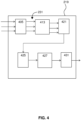
- the method includes streaming 129 pixel values 501 from each of multiple sensors in a frame independent-manner through a pipeline 231 on a processing device 219.
- the pipeline 231 includes a kernel operation 135 that identifies saturated pixel values.
- the pixel values 501 are merged 139.
- the HE and ME exposures are separated by 12.2 ⁇ (3.61 stops) and the ME and LE are separated by 17.0 ⁇ (4.09 stops), which means that this configuration is designed to extend the dynamic range of the sensor by 7.7 stops.
- the system is simplified with 4-bit sensors (as opposed to the 12-bit sensors as may be used in apparatus 201), which measure only 16 unique brightness values and the sensors are separated by only 1 stop (a factor of 2) in exposure. Since CMOS sensors exhibit an approximately linear relationship between incident exposure and their output value, the values from the three sensors are graphed as a linear function of incident irradiance instead of the traditional logarithmic scale.
- the merging 139 includes a specific operation for each of the four cases for the pixel 615 on sensor 213 and its neighborhood 601 (see FIG. 6 ):
- the apparatus 201 may be implemented using three Silicon Imaging SI-1920HD high-end cinema CMOS sensors mounted in a camera body. Those sensors have 1920 ⁇ 1080 pixels (5 microns square) with a standard Bayer color filter array, and can measure a dynamic range of around 10 stops (excluding noise). The sensors are aligned by aiming the camera at small pinhole light sources, locking down the HE sensor and then adjusting setscrews to align the ME and LE sensors.
- each image sensor may be said to have its own “color correction space” whereby images from that sensor need to be corrected out of that color correction space to true color.
- the optical system can be calibrated (e.g., by taking a picture of a calibration card) and a color correction matrix can be stored for each image sensor.
- the HDR video pipeline can then perform the counter-intuitive step of adjusting the pixel values from one sensor towards the color correction of another sensor-which may in some cases involve nudging the colors away from true color.
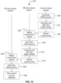
- the color correction process 1001 converts one sensor's data from its color correction space to the color correction space of another sensor, before merging the images from the two sensors.
- the merged image data can then be converted to the color correction space of a third sensor, before being combined with the image data from that third sensor.
- the process may be repeated for as many sensors as desired. After all sensors' images have been combined, the final combined image may be demosaiced 145 and then may be color corrected to truth.
- the color correction matrices from one or more sensors can be used. This process may be referred to as converting between color correction spaces or calibrating color correction spaces. Neither the first color correction space nor the second color correction space accurately reflects the true color of the captured image. The first and the second color correction space both have inaccuracies, and those inaccuracies are, in general, different from one another. Thus RGB values from each sensor must be multiplied by a unique color correction matrix for those RGB values to appear as true colors.
- Methods of the invention allow matching of the color correction space of the second sensor to the color correction space of the first sensor so that the images from the two sensors may be accurately combined, or merged.
- the method for applying all the inaccuracies of the second color correction space to the first color correction space, prior to combining images from the two into an HDR image is previously unknown.
- Typical methods for combining data from multiple CFA sensors rely on color-correcting each sensor's data to the "truth" values measured from a calibrated color card, prior to combining the images. This is problematic in an HDR system, where it is known that the brighter sensor's image will have significant portions that are saturated, which saturated portions should actually have been utilized from the darker sensor's image when combining.
- the solution provided in the present invention avoids this saturated-pixel color misidentification problem by performing the steps of [(a) demosaic 1045, (b) color correct 1051 & (c) mosaic 1057] data from the darker sensor, thereby ensuring all data is accurately returned to its non-demosaiced state prior to the step of merging the darker sensor's data with the brighter sensor's data.
- the merged non-demosaiced image within the ME color correction space is then demosaiced 1067.
- This demosaicing 1064 is similar to the demosaicing 1045 described above, except the CFA pixel values undergoing the demosaicing process are now associated with the ME color correction space.
- the demosaicing 1067 produces RGB vectors in the ME color space. Those RGB vectors are transformed 1071 into the HE color space while also being color corrected ([B][A]-1[RGB]). Equation 2 shows how to use the color correction matrix to correct the color values of the ME sensor.
- the color corrected ME information is transformed 1071 from the ME color correction space to the HE color correction space by multiplying the ME color correction matrix by the inverse of the SE color correction matrix.
- the pipeline After the color processing and tone-mapping, the pipeline has produced an HDR video signal.
- the HDR signal may be subject to HDR compression by a suitable operation (e.g., JPEG or similar).
- the pair of streams includes the 8-bit SDR signal and the compressed HDR residual signal, which provides for HDR display.
- This dual signal is broadcast over a communication network and may in-fact be broadcast over television networks, cellular networks, or the Internet.
- a device that receives the signal displays the video according to the capacity of that device.
- An SDR display device will "see" the 8-bit SDR signal and display a video at a dynamic range that is standard, which signal has also had a certain TMO applied to it.
- An HDR display device will decompress the residuals and combine the dual streams into an HDR signal and display HDR video.
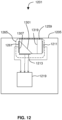
- FIG. 12 shows image sensors and processor of an apparatus 1201 for HDR video processing according to certain embodiments.
- the apparatus 1201 includes a processing device 1219 such as a field-programmable gate array (FPGA) or an application-specific integrated circuit (ASIC).
- a plurality of image sensors 1265 are coupled to the processing device 219 and also to an optical assembly 1259 (e.g., a glass or crystal cube or slab having one or more beamsplitter 1301 therein).
- the apparatus 1201 is configured to stream pixel values from each of the plurality of image sensors 1265 in a frame independent-manner through a pipeline on the processing device 1219.
- the pipeline includes a kernel operation that identifies saturated pixel values and a merge module to merge the pixel values to produce an HDR image.
- the kernel operation operates on pixel values as they stream from each of the plurality of image sensors 1265 by examining, for a given pixel on the HE sensor 1213, values from a neighborhood of pixels surrounding the given pixel, finding saturated values in the neighborhood of pixels, and using information from a corresponding neighborhood on the ME sensor 1211 to estimate a value for the given pixel.
- the apparatus 1201 may also include or be optically connected to a lens and at least one beamsplitter 1301.
- the HE sensor 1213, the ME sensor 1211, the lens 1311 and the at least one beamsplitter 1301 are arranged to receive an incoming beam of light 1305 and split the beam of light 305 into at least a first path that impinges and HE sensor 1213 and a second path that impinges on the ME sensor 1211.
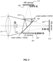
- the apparatus 1201 uses a set of partially-reflecting surfaces to split the light from a single photographic lens 1311 so that it is focused onto three imaging sensors simultaneously.
- the light is directed back through one of the beamsplitters a second time, and the three sub-images are not split into red, green, and blue but instead are optically identical except for their light levels.
- the beamsplitter 1301 reflects 8% of the light from the lens upwards, toward the second uncoated beamsplitter 1319, which has the same optical properties as the first but is positioned at a 90 ⁇ angle to the light path and has an approximate T/R ratio of 94/6. Of the 8% of the total light that is reflected upwards, 94% (or 7.52% of the total light) is transmitted through the second beamsplitter 1319 and focused onto the medium-exposure (ME) sensor 211.
- ME medium-exposure
- the HE, ME and LE sensors capture images with 92%, 7.52%, and 0.44% of the total light gathered by the camera lens, respectively.
- the HE and ME exposures are separated by 12.2 ⁇ (3.61 stops) and the ME and LE are separated by 17.0 ⁇ (4.09 stops), which means that this configuration is designed to extend the dynamic range of the sensor by 7.7 stops.
- Embodiments of the invention may include the features of the following enumerated paragraphs ("paras").
Landscapes
- Physics & Mathematics (AREA)
- Engineering & Computer Science (AREA)
- Multimedia (AREA)
- Signal Processing (AREA)
- General Physics & Mathematics (AREA)
- Optics & Photonics (AREA)
- Spectroscopy & Molecular Physics (AREA)
- Human Computer Interaction (AREA)
- Color Television Image Signal Generators (AREA)
- Studio Devices (AREA)
- Transforming Light Signals Into Electric Signals (AREA)
- Image Processing (AREA)
Applications Claiming Priority (5)
| Application Number | Priority Date | Filing Date | Title |
|---|---|---|---|
| US201662294820P | 2016-02-12 | 2016-02-12 | |
| US15/169,006 US10257393B2 (en) | 2016-02-12 | 2016-05-31 | Devices and methods for high dynamic range video |
| US201662409053P | 2016-10-17 | 2016-10-17 | |
| EP17750844.7A EP3414890B1 (de) | 2016-02-12 | 2017-02-10 | Vorrichtungen und verfahren für video mit hochdynamischem bereich |
| PCT/US2017/017396 WO2017139596A1 (en) | 2016-02-12 | 2017-02-10 | Devices and methods for high dynamic range video |
Related Parent Applications (1)
| Application Number | Title | Priority Date | Filing Date |
|---|---|---|---|
| EP17750844.7A Division EP3414890B1 (de) | 2016-02-12 | 2017-02-10 | Vorrichtungen und verfahren für video mit hochdynamischem bereich |
Publications (2)
| Publication Number | Publication Date |
|---|---|
| EP4270976A2 true EP4270976A2 (de) | 2023-11-01 |
| EP4270976A3 EP4270976A3 (de) | 2024-01-10 |
Family
ID=59564045
Family Applications (2)
| Application Number | Title | Priority Date | Filing Date |
|---|---|---|---|
| EP23189756.2A Pending EP4270976A3 (de) | 2016-02-12 | 2017-02-10 | Vorrichtungen und verfahren für video mit hochdynamischem bereich |
| EP17750844.7A Active EP3414890B1 (de) | 2016-02-12 | 2017-02-10 | Vorrichtungen und verfahren für video mit hochdynamischem bereich |
Family Applications After (1)
| Application Number | Title | Priority Date | Filing Date |
|---|---|---|---|
| EP17750844.7A Active EP3414890B1 (de) | 2016-02-12 | 2017-02-10 | Vorrichtungen und verfahren für video mit hochdynamischem bereich |
Country Status (5)
| Country | Link |
|---|---|
| EP (2) | EP4270976A3 (de) |
| JP (1) | JP6997461B2 (de) |
| AU (1) | AU2017217833B2 (de) |
| CA (1) | CA3016428C (de) |
| WO (1) | WO2017139596A1 (de) |
Families Citing this family (10)
| Publication number | Priority date | Publication date | Assignee | Title |
|---|---|---|---|---|
| US10264196B2 (en) | 2016-02-12 | 2019-04-16 | Contrast, Inc. | Systems and methods for HDR video capture with a mobile device |
| US10257394B2 (en) | 2016-02-12 | 2019-04-09 | Contrast, Inc. | Combined HDR/LDR video streaming |
| US9979906B2 (en) | 2016-08-03 | 2018-05-22 | Waymo Llc | Beam split extended dynamic range image capture system |
| JP7081835B2 (ja) | 2016-08-09 | 2022-06-07 | コントラスト, インコーポレイテッド | 車両制御のためのリアルタイムhdrビデオ |
| US10951888B2 (en) | 2018-06-04 | 2021-03-16 | Contrast, Inc. | Compressed high dynamic range video |
| EP3837635A4 (de) | 2018-08-14 | 2022-04-27 | Contrast, Inc. | Bildkomprimierung |
| JP6765494B1 (ja) | 2019-10-31 | 2020-10-07 | パナソニックi−PROセンシングソリューションズ株式会社 | 3板式カメラ |
| FR3123734B1 (fr) * | 2021-06-02 | 2024-10-25 | Univ Bourgogne | Procédé de traitement de données de pixels, dispositif et programme correspondant |
| CN118435699A (zh) * | 2021-12-22 | 2024-08-02 | 环球城市电影有限责任公司 | 双向cbrs通信系统和方法 |
| CN115379092A (zh) * | 2022-08-17 | 2022-11-22 | 中南大学 | 一种高动态范围视频获取方法、系统及终端 |
Family Cites Families (13)
| Publication number | Priority date | Publication date | Assignee | Title |
|---|---|---|---|---|
| JPH08220585A (ja) * | 1995-02-13 | 1996-08-30 | Nikon Corp | 電子カメラ |
| US7084905B1 (en) | 2000-02-23 | 2006-08-01 | The Trustees Of Columbia University In The City Of New York | Method and apparatus for obtaining high dynamic range images |
| JP4818609B2 (ja) | 2002-08-21 | 2011-11-16 | ジェンテックス コーポレイション | 外部車両照明の自動制御のための画像取得及び処理方法 |
| KR20080038929A (ko) * | 2006-10-31 | 2008-05-07 | 삼성전기주식회사 | 적외선 차단막 일체형 렌즈 및 이를 이용한 카메라 모듈 |
| JP5631299B2 (ja) * | 2008-03-28 | 2014-11-26 | コントラスト オプティカル デザイン アンド エンジニアリング,インク. | 全ビーム画像スプリッタシステム |
| WO2009153836A1 (en) * | 2008-06-19 | 2009-12-23 | Panasonic Corporation | Method and apparatus for motion blur and ghosting prevention in imaging system |
| AU2010221241A1 (en) * | 2009-03-04 | 2011-10-27 | Paul A. Wagner | Temporally aligned exposure bracketing for high dynamic range imaging |
| GB2500835B (en) * | 2010-12-10 | 2014-02-12 | Ibm | High-dynamic range video tone mapping |
| US9270875B2 (en) * | 2011-07-20 | 2016-02-23 | Broadcom Corporation | Dual image capture processing |
| US9437171B2 (en) * | 2012-12-05 | 2016-09-06 | Texas Instruments Incorporated | Local tone mapping for high dynamic range images |
| US9071765B2 (en) | 2012-12-28 | 2015-06-30 | Nvidia Corporation | System, method, and computer program product implementing an image processing pipeline for high-dynamic range images |
| US9568713B2 (en) * | 2013-01-05 | 2017-02-14 | Light Labs Inc. | Methods and apparatus for using multiple optical chains in parallel to support separate color-capture |
| US9131150B1 (en) * | 2014-06-06 | 2015-09-08 | Amazon Technologies, Inc. | Automatic exposure control and illumination for head tracking |
-
2017
- 2017-02-10 WO PCT/US2017/017396 patent/WO2017139596A1/en not_active Ceased
- 2017-02-10 EP EP23189756.2A patent/EP4270976A3/de active Pending
- 2017-02-10 CA CA3016428A patent/CA3016428C/en active Active
- 2017-02-10 AU AU2017217833A patent/AU2017217833B2/en active Active
- 2017-02-10 EP EP17750844.7A patent/EP3414890B1/de active Active
- 2017-02-10 JP JP2018561188A patent/JP6997461B2/ja active Active
Non-Patent Citations (1)
| Title |
|---|
| DEBEVECMALIK: "Recovering high dynamic range radiance maps from photographs", PROCEEDINGS OF ACM SIGGRAPH, 1997, pages 369 - 378 |
Also Published As
| Publication number | Publication date |
|---|---|
| JP6997461B2 (ja) | 2022-01-17 |
| CA3016428C (en) | 2024-01-09 |
| AU2017217833B2 (en) | 2021-10-07 |
| JP2019506821A (ja) | 2019-03-07 |
| EP3414890A4 (de) | 2019-09-18 |
| WO2017139596A1 (en) | 2017-08-17 |
| AU2017217833A1 (en) | 2018-09-06 |
| EP4270976A3 (de) | 2024-01-10 |
| CA3016428A1 (en) | 2017-08-17 |
| EP3414890A1 (de) | 2018-12-19 |
| EP3414890B1 (de) | 2023-08-09 |
Similar Documents
| Publication | Publication Date | Title |
|---|---|---|
| US12212728B2 (en) | Devices and methods for high dynamic range video | |
| AU2017217833B2 (en) | Devices and methods for high dynamic range video | |
| US10511785B2 (en) | Temporally aligned exposure bracketing for high dynamic range imaging | |
| JP2011010108A (ja) | 撮像制御装置、撮像装置及び撮像制御方法 | |
| Hubel | Foveon technology and the changing landscape of digital cameras | |
| CN121665126A (zh) | 一种成像方法、系统以及装置 |
Legal Events
| Date | Code | Title | Description |
|---|---|---|---|
| PUAI | Public reference made under article 153(3) epc to a published international application that has entered the european phase |
Free format text: ORIGINAL CODE: 0009012 |
|
| STAA | Information on the status of an ep patent application or granted ep patent |
Free format text: STATUS: THE APPLICATION HAS BEEN PUBLISHED |
|
| AC | Divisional application: reference to earlier application |
Ref document number: 3414890 Country of ref document: EP Kind code of ref document: P |
|
| AK | Designated contracting states |
Kind code of ref document: A2 Designated state(s): AL AT BE BG CH CY CZ DE DK EE ES FI FR GB GR HR HU IE IS IT LI LT LU LV MC MK MT NL NO PL PT RO RS SE SI SK SM TR |
|
| REG | Reference to a national code |
Ref country code: DE Ref legal event code: R079 Free format text: PREVIOUS MAIN CLASS: H04N0023800000 Ipc: H04N0023740000 |
|
| PUAL | Search report despatched |
Free format text: ORIGINAL CODE: 0009013 |
|
| AK | Designated contracting states |
Kind code of ref document: A3 Designated state(s): AL AT BE BG CH CY CZ DE DK EE ES FI FR GB GR HR HU IE IS IT LI LT LU LV MC MK MT NL NO PL PT RO RS SE SI SK SM TR |
|
| RIC1 | Information provided on ipc code assigned before grant |
Ipc: H04N 23/74 20230101AFI20231206BHEP |
|
| STAA | Information on the status of an ep patent application or granted ep patent |
Free format text: STATUS: REQUEST FOR EXAMINATION WAS MADE |
|
| 17P | Request for examination filed |
Effective date: 20240704 |
|
| RBV | Designated contracting states (corrected) |
Designated state(s): AL AT BE BG CH CY CZ DE DK EE ES FI FR GB GR HR HU IE IS IT LI LT LU LV MC MK MT NL NO PL PT RO RS SE SI SK SM TR |
|
| GRAP | Despatch of communication of intention to grant a patent |
Free format text: ORIGINAL CODE: EPIDOSNIGR1 |
|
| STAA | Information on the status of an ep patent application or granted ep patent |
Free format text: STATUS: GRANT OF PATENT IS INTENDED |
|
| INTG | Intention to grant announced |
Effective date: 20260313 |