EP4271132B1 - Ensemble cavité de four avec fonction de chauffage à micro-ondes pour chauffer un comestible - Google Patents
Ensemble cavité de four avec fonction de chauffage à micro-ondes pour chauffer un comestible Download PDFInfo
- Publication number
- EP4271132B1 EP4271132B1 EP22171043.7A EP22171043A EP4271132B1 EP 4271132 B1 EP4271132 B1 EP 4271132B1 EP 22171043 A EP22171043 A EP 22171043A EP 4271132 B1 EP4271132 B1 EP 4271132B1
- Authority
- EP
- European Patent Office
- Prior art keywords
- cavity
- front frame
- choke
- profile
- cavity member
- Prior art date
- Legal status (The legal status is an assumption and is not a legal conclusion. Google has not performed a legal analysis and makes no representation as to the accuracy of the status listed.)
- Active
Links
Images


Classifications
-
- H—ELECTRICITY
- H05—ELECTRIC TECHNIQUES NOT OTHERWISE PROVIDED FOR
- H05B—ELECTRIC HEATING; ELECTRIC LIGHT SOURCES NOT OTHERWISE PROVIDED FOR; CIRCUIT ARRANGEMENTS FOR ELECTRIC LIGHT SOURCES, IN GENERAL
- H05B6/00—Heating by electric, magnetic or electromagnetic fields
- H05B6/64—Heating using microwaves
- H05B6/76—Prevention of microwave leakage, e.g. door sealings
Definitions
- the invention relates to a cavity assembly for an oven with microwave heating function for heating comestible, an assembly method for such a cavity assembly, and an oven with such a cavity assembly with microwave heating function for heating comestible.
- Ovens with microwave heating function for heating comestible are sufficiently known in various embodiments.
- An important safety aspect of such an oven is that the user must be shielded from microwave radiation.
- failures can occur in the electronics of the oven if microwave radiation is emitted from the front side of the cavity in which comestible can be placed for heating and is reflected from the rear side.
- JP H07 1197U dicloses a cavity assembly according to the preamble of claim 1.
- the present invention is based on the task of at least partially overcoming the disadvantages known from the prior art.
- the features according to the invention result from the independent claims, for which advantageous embodiments are shown in the dependent claims.
- the features of the claims can be combined in any technically sensible manner, wherein the explanations from the following description as well as features from the figures, which comprise supplementary embodiments of the invention, can also be consulted for this purpose.
- the invention relates to a cavity assembly for an oven having microwave heating function for heating comestible, the cavity assembly having a front side and a rear side, the front side being the side accessible in use, the cavity assembly comprising at least the following components:
- the cavity assembly is characterized in particular by that the two flanges are embraced at least in sections by at least one common choke profile, the choke profile being configured for blocking against microwave radiation.
- ordinal numbers used in the preceding and following descriptions are merely for the purpose of unambiguous distinguishability and do not reflect any order or ranking of the designated components. An ordinal number greater than one does not imply that another such component must necessarily be present.
- the oven for which the cavity assembly is arranged is functionally designed, for example, as conventionally known.
- the oven comprises a heatable treatment chamber for treating food, mostly comprising a top wall, a bottom wall, two opposing lateral walls, a frontal opening and a door for closing and opening the frontal opening.
- the oven is arranged for heating comestible by means of microwave radiation.
- the cavity assembly comprises a cavity member and a front frame.
- the cavity member encloses with its walls on a plurality of sides an interior space in which comestible can be placed.
- the cavity member is preferably formed in one piece.
- the cavity member has further structural elements which are, for example, screwed on, riveted, welded on or soldered/brazed on and are mounted before, during or after being connected to the front frame.
- the cavity member is preferably a formed, for example deep-drawn, sheet metal component.
- the cavity member is preferably closed by means of its walls on five sides of an imaginary parallelepiped, often with the shape of the cavity member being somewhat more complex than the shape of a parallelepiped, for example with chamfered edges and corners, indentations and/or passages. Passages are formed, for example, for structural elements, for example, screws, light, ventilation, supply lines, and/or an inlet for microwave radiation from a microwave source located outside the interior of the cavity member.
- At least one passage in use in an oven is not closed, but merely suitably covered against excessive leakage of microwave radiation.
- a frontal opening is formed from the cavity member to the front side, which can be closed by means of a door of the oven.
- the front frame has the function to bear against the closed door and reduce escape of heat, humidity, and microwave radiation.
- the cavity assembly is further adapted for steam cooking, wherein at least one inlet and outlet for steam from at least one steam source arranged outside the interior of the cavity member is accordingly provided and/or at least one steam source is arranged inside the cavity member.
- an oven comprises a water source, for example a tank and/or a water connection for a household water pipe.
- a water source for example a tank and/or a water connection for a household water pipe.
- the cavity member or its interior is visible to the user from the front side through the frontal opening when the door is open.
- a front frame is attached to the front side of the cavity member.
- the front side is the side that faces the user in use and can be closed with the door of the oven.
- the oven is frequently integrated into a kitchen unit, for example, so that the rear side opposite the front side is not accessible, for example, it is aligned with a wall.
- the lateral sides of the oven adjoin, for example, adjacent kitchen elements, for example cabinet elements or other kitchen appliances, or at least one lateral side is exposed.
- the top side, or rather its surface normal pointing away from the interior of the cavity member points upward, and the bottom side points downward, with respect to the earth gravity field.
- the cavity member also partially covers the front side with a wall i.e., partially encloses the interior space.
- the cavity member does not comprise a wall that encloses the interior space towards the front side.
- at least one flange is provided, for example, which extends at least in part parallel to the front side, preferably outwardly i.e., away from the frontal opening of the cavity member.
- such a flange is formed circumferentially in the plane of the front side face.
- Such a flange is adapted to be connected to the front frame, for example.
- the flanges of the cavity member and of the front frame in one embodiment surround respective frontal opening of the cavity member and a corresponding central opening in the front frame.
- the front frame is set up as a door frame for the door of the oven.
- the front frame is permanently, preferably directly, connected to the cavity member in use.
- the front frame then correspondingly comprises a receptacle for a hinge or joint for the door and/or a gasket element for abutment against the door when the door is closed.
- the front frame comprises a plurality of openings for venting, for example, to remove heat and/or moisture.
- the front frame itself is not completely closed by the door of the oven, but a channel is provided to the outside, for example to the front side. Nevertheless, an interior space of the cavity member is completely closed by means of the door, at least with respect to microwave radiation i.e., on all six sides.
- microwave radiation is also allowed to escape up to a permissible small extent to the front side, i.e., through a door or a slot between the door and the front frame or cavity member or gasket element.
- the microwave radiation is then reduced to such a small extent that it is classified as harmless and may thus be considered technically shielded.
- the microwave radiation is then also referred to hereafter as blocked.
- the choke profile has a specific structure that is itself tight against microwave radiation, and, thus, absorbs or reflects microwave radiation.
- the front frame surrounds the frontal opening of the cavity member.
- the front frame has a corresponding opening that surrounds the frontal opening of the cavity member.
- the front frame is connected to the cavity member immediately adjacent to the frontal opening.
- the front frame is connected to the cavity member outside the frontal opening i.e., towards the upper side, the lower side or one of the lateral sides, respectively, at a distance from the frontal opening.
- a gap is formed between the cavity member and the front frame.
- Such a gap is open, for example, for receiving a gasket element.
- the gap is partially closed at least once, preferably multiple times, for forming a connecting element between the cavity member and the front frame.
- the front frame is preferably formed in one piece.
- the front frame has further structural elements which are, for example, screwed on, riveted, welded on or soldered/brazed on and are mounted before, during or after connection to the cavity member.
- the cavity member at the frontal opening comprises a cavity-side flange and the front frame comprises a frame-side flange.
- the cavity-side flange is connected to the cavity member, preferably formed integrally therewith, particularly preferably from a blank, for example by means of deep drawing from a sheet metal component.
- the frame-side flange is connected to the front frame, preferably formed integrally therewith, particularly preferably from a blank, for example by means of cold forming, for example folding over, from a sheet-metal component.
- the flanges extend at least with a part towards the rear side, preferably parallel to the upper side, lower side or lateral side. In an advantageous embodiment, the two flanges are aligned parallel to each other.
- the flanges are formed circumferentially around the frontal opening.
- the flanges are formed from a plurality of individual flange elements, of which an intended circumferential element is formed collectively.
- the flanges are uniquely interrupted by fastening portions and/or passages.
- at least one of the flanges comprises at least one fastening element for connection to the front frame and/or the cavity member.
- the cavity member and the front frame are connected to each other by means of said flanges, for example exclusively by means of said flanges.
- said flanges are formed extending to the rear side outside of fastening portions, for example apart from the previously described fastening elements, preferably parallel to each other.
- the ends of the flanges i.e., the open ends, in one embodiment have an end formation, for example a flanged edge or a rounding, which deviate from the original extension towards the rear side.
- the respective open end of one of the flanges is a planar extension of the rear side extension i.e., the relevant flange is planar up to a cut edge or up to a rounded end.
- the region of the flat outward and/or inward extension of a flange at least in sections, at least one elevation with outward and/or inward deviation from the flat surface or a hole is provided.
- the choke profile is designed to prevent, to a technical degree, the passage of at least such microwave radiation that has been introduced into the interior of the cavity member. This means that a permissible or uncritical amount of microwave radiation is allowed to pass through. This is not a matter of protecting a user. Rather, the electronics located in the oven and outside the cavity member are protected from excessive intensity or frequentness of a microwave radiation. For example, the probability of a radiation angle is also taken into account for an estimation of a frequentness, so that not necessarily every slot has to be blocked, but for example a coverage of, for example, at least 70% to 90% of a passage area to be blocked is sufficient. Alternatively, at least technically complete coverage is achieved.
- the choke profile is set up in such a way that, in use, it embraces both, the cavity-side flange and the frame-side flange.
- a choke profile is easy to install and at the same time forms an effective barrier against microwave radiation.
- the choke profile is formed with a microwave radiation absorbing and/or reflecting material.
- a material is, for example, a metal or a plastic with itself electrically conductive properties or embedded aggregates, for example metallic particles or fibers.
- the choke profile is a cold-formed sheet element, wherein, in addition to metallic sheets, so-called organo sheets are also a suitable material.
- the choke profile is self-retaining, wherein low friction forces or spot soldering/brazing or welding are sufficient for self-retaining due to the purely static load in use.
- the choke profile is designed to be self-retaining in such a way that it is highly unlikely or certain not to fall off during transport without further securing.
- no other measure is necessary for the (self-retaining) mounting of the choke profile.
- the choke profile embraces the two flanges in such a way that contact, preferably direct contact, is formed with both the cavity-side flange and the frame-side flange.
- the choke profile is of one-piece and simple design, wherein further separate elements are not provided and are not mounted later.
- the choke profile is designed as a U-profile, with the two flanges engaging in the U-profile in the assembled state.
- a U-profile in a simple design has a back and two arms extending from the back.
- that U-profile is made by extrusion molding.
- a gap is formed between the two flanges and thus between the cavity member and the front frame.
- This gap is formed circumferentially or only in sections.
- such a gap is provided as an interruption of heat conduction i.e., to prevent heat transfer by direct contact.
- the gap is closed and there, for example directly, the front frame is in contact with the cavity member.
- a sufficient barrier against microwave radiation is often already formed, so that no additional element for blocking is necessary here.
- the gap is covered by means of the choke profile everywhere; preferably everywhere except for gaps due to technical reasons, for example due to necessary clearance for assembly.
- the choke profile is applied from the rear side over the two flanges, for example pushed on, so that the gap is thus covered from the rear side.
- the two flanges are aligned parallel to each other so that the choke profile can be easily applied on to the two flanges and the flanges are thus embraced by the (common) choke profile.
- the flanges are aligned parallel to the direction of insertion of comestible into the interior of the cavity member, for example a direction which is perpendicular to the frontal opening of the cavity member. Alternatively or additionally, this insertion direction is oriented transverse to the earth gravity field and directed from the front side to the back when the cavity assembly is mounted in an oven in use.
- the gap to the front side is closed, at least in sections, by a gasket element.
- the gap towards the front side is closed with a gasket element, for example as previously described.
- the gasket element is arranged for gasketingly abutting the door of an oven, in the state in which the door is closed.
- the gasket element is designed with a barb such that it plunges through the gap behind at least one of the flanges or engages in a hole in one of the flanges to secure the position of the gasket element, preferably under tensile stress.
- the gasket element is, for example, of conventional design and the choke profile is preferably arranged, in view from the front side, overlapping and/or in the same circumferential manner, preferably apart from any fastening portions, as the gasket element, while preferably the choke profile and the gasket element are not physically overlapping each other.
- the gasket element for example a barbed hook of the gasket element, is configured and arranged as a friction element for the choke profile, wherein on the one hand a spring effect is formed on the choke profile and on the other hand, due to the surface of the gasket element, a pairing with a higher coefficient of friction and thus increased friction locking is provided.
- the choke profile has a plurality of inwardly extending tongues, wherein preferably the tongues each have a, more preferably wedge-shaped, tongue-gap with respect to one another.
- the choke profile entirely or in sections preferably for a rounding of the cavity member or a sharp-edged corner of the cavity member, which both are referred to here as a corner portion, has a plurality of inwardly extending tongues.
- Inward is the direction from the outside toward the inside of the cavity member and, for example, along a radius with the insertion direction defined above as the axis.
- these tongues are spaced apart from each other, preferably by means of a wedge-shaped tongue-gap, so that the choke profile for a corner portion is suitable for reshaping the respective curve or corner without the tongues interfering with each other.
- the tongue and the respective tongue-gap extend over the back, at least partially, and one of the arms extending from the back.
- the other arm does not have i.e., is free of, a tongue and tongue-gap.
- the shape of the tongue-gap is designed for an exact rounding radius or, if necessary, also a variable rounding radius.
- the tongue-gap is designed in such a way that a minimum rounding radius is possible without overlapping the tongues, but the choke profile for a corner portion can also be used for a larger rounding radius. In this case, the remaining deformed tongue-gap between the tabs after forming the choke profile is sufficiently small to achieve the above-mentioned desired barrier effect against microwave radiation.
- the tongues are made to overlap with each other after forming.
- a pin-shaped tongue-gap is formed, with the pin head-shape being a start of the tongue-gap in the material of the choke profile and the needle-shape is extending from the pin head-shape to the end portion of the tongues.
- the respective adjacent tongues are arranged offset from each other in the direction of the extension of the flanges and overlap each other after fitting to the respective non-straight portion of the cavity member, if necessary.
- the choke profile includes tongues over various sections or its entire extension parallel to the flanges, whereby the choke profile is configured to be adapted to an individual shape of the flanges to be embraced.
- the choke profile is provided in an arbitrary length of extension, preferably in a standardized length, and is to be cut for the present section of the flanges to be embraced. Having a plurality of tongues or tongues over the entire extension, it can be adapted to the present individual shape of the flanges to be embraced e.g., one or more corner portions within the present section to be embraced.
- the tongue-gaps are designed to allow the choke profile to be adapted to a non-straight portion of the cavity member, for example, to be adapted by hand or with at least sufficiently low force so that this can be performed with a hand tool, such as pliers.
- the choke profile is made of metal, preferably of stainless steel.
- the choke profile is formed from a metal, thus, being an electric conductive material absorbing and reflecting microwave radiation.
- the choke profile is made of spring steel allowing for high clamping forces and/or long durability of a clamping force over a long service life.
- Stainless steel has several advantageous properties for the intended use. On the one hand, very good corrosion resistance is achievable, which is particularly advantageous for use in an oven with a steam cooking function, for example.
- material strength is achievable that even in the case of an embracing with an undersize, the choke profile achieves such sufficient elastic dimensional stability over a desired service life that it can be designed to be self-retaining over this service life, which can be the case for non-stainless metals, too.
- such a choke profile made of a stainless steel is easy to machine and, due to the high corrosion resistance, no special protective measures are necessary to provide special protection for the surface of the choke profile during, for example, cold forming and or thermal finishing.
- the choke profile for embracing the two flanges has at least an elastic undersize relative to the two flanges to be embraced.
- the choke profile is undersized relative to the distance between the respective back sides and contact faces, respectively, of the flanges with which the choke profile comes into contact in the assembled state.
- Such a choke profile can be pushed onto the two flanges. Due to the undersize, preferably within the elastic deformation of the choke profile, for example a U-profile, a clamping is created between the choke profile and the two flanges. This ensures sufficient friction locking for self-retaining mounting of the choke profile on the two flanges by simple means.
- the choke profile comprises a guide surface for areal contact with one of the two flanges and, additionally, comprises a contact tab which is constructed to form a contact line with the other flange.
- the choke profile has a guide surface on the one hand and a contact tab on the other.
- the contact tab is designed to form a technical contact line with one of the two flanges which is overlapped.
- the contact line is a continuous line across the e.g., circumferential, extent of the choke profile or a plurality of contact points through which an imaginary line can be drawn.
- This contact line is not necessarily straight.
- the contact plate thus has a kink which has an elevation facing the respective flange. Preferably, this kink is spaced with an, particularly preferably purely elastic, undersize in comparison to the opposite guide surface.
- the guide surface is set up for areal i.e., two-dimensional, contact, wherein here too the areal contact is to be regarded as two-dimensional from a purely technical point of view and it is irrelevant here whether the guide surface is in contact with the respective flange via a plurality of, for example stochastically distributed, points and/or lines.
- the guide surface is implemented by a plurality of kinks, wherein the kink extension i.e., the ridge of such a kink, has a vector component in the mounting direction, for example is aligned parallel to the mounting direction. Such kinks are perpendicular to above-mentioned kink of the contact tab.
- a thermal break is formed in that heat conduction is limited to the contact line.
- the contact line is formed on the cavity-side flange, so that the choke profile is already only slightly heated.
- the choke profile has such a contact tab on both sides, and preferably a guide portion is also provided by means of which the choke profile is guided to at least one of the flanges in such a way that simple and safe assembly of the choke profile is ensured.
- the choke profile has two guide surfaces, each for areal contact with one of the two flanges.
- the choke profile has a mounting widening on its front side.
- the mounting widening is preferably designed in such a way that the choke profile can be placed on the flanges without elastic deformation and can be guided safely onto the two flanges even with limited visibility.
- a mounting widening or another guide device for the choke profile prevents the choke profile from being guided over only one of the two flanges, which false mounting position would not ensure the barrier effect against microwave radiation.
- a straight choke profile for a straight portion of the cavity member and/or the front frame and a rounded choke profile for a corner portion of the cavity member and the front frame are one piece.
- a straight choke profile and at least one rounded choke profile for a corner portion of the cavity member are formed in one piece.
- the choke profiles are formed from a common sheet, joined together with another before assembly, for example by welding.
- a circumferential profile is formed including a plurality of straight and rounded choke profiles, with preferably corresponding recesses being formed for any fastening portions between the cavity member and the front frame
- a straight choke profile is provided with one or two rounded or roundable choke profiles, the roundable choke profiles being adaptable for the respective corner portion, so that such a profile can be used for a plurality of cavity assemblies in different embodiments.
- a straight portion of the cavity member is not necessarily a straight portion of the front frame and vice versa. Rather, for example, a curve is formed on one of them, for example, for a passage or installation of another element.
- the friction locking i.e., a gripping fixation
- the choke profile is a, preferably metal, clamp corresponding to the flanges brought into alignment with each other.
- the positive locking i.e., a fixation with corresponding interlocking structures
- the material locking i.e., a chemical or physical bond between substrates or their contacted surfaces, is formed by means of welding spots and/or soldering/brazing spots.
- a combination is applied, preferably of friction and positive locking.
- the cavity member and the front frame are non-destructively detachably connected to each other.
- the cavity member and the front frame are not welded together, for example, but can be dismantled from each other again by simple means.
- the cavity member and the front frame are screwed together.
- the two elements are riveted together, wherein neither the cavity member nor the front frame are damaged if the rivets are removed accordingly, for example drilled out.
- An advantage of non-destructively joined elements is that the two elements can have material property or surface property independent from requirements for welding and/or the order of assembly and surface treatment can be designed more flexible.
- the cavity member is double enamelled and the front frame is single enamelled.
- the cavity assembly it is particularly advantageous for an oven with a steam cooking function, so that the cavity member, which is exposed to the steam, is sufficiently corrosion resistant due to a double enamel coating, and the front frame, which is not exposed to the steam or is exposed to it to a significantly lesser extent, only needs to be single enamelled. If, for example, the cavity member and the front frame are welded together, the front frame must be enamelled as well when the cavity member is enamelled. Due to the thermal treatment of enamelling, it is a complex task to prevent distortion of the cavity member. Significant costs can therefore be saved here.
- an assembly method for a cavity assembly comprising the following steps:
- the assembly of the cavity assembly can be carried out in a particularly simple and cost-efficient manner.
- the cavity member and the front frame and the required number of choke profiles are provided, depending on the embodiment. It should be noted that the providing in the step a. does not have to take place simultaneously and that at least one of the choke profiles is provided, for example, only at the step c.. In a preferred embodiment, steps a., b., and c. take place in alphabetical order.
- step b. the front frame and the cavity member are aligned with each other so that the front frame can be connected to the cavity member at the frontal opening.
- the front frame is already connected to the cavity member, for example screwed or riveted.
- the front frame and the cavity member are connected to each other in a non-destructively detachable manner.
- step c. the at least one choke profile is applied to the two flanges such that the choke profile is adapted to block microwave radiation in operation of the oven housing the cavity assembly as described above.
- step c. the connection between the front frame and the cavity member is made.
- step d. before step a. the cavity member and the front frame have been final surface treated.
- the cavity member and the front frame are already provided with a surface treatment before step a. is carried out.
- the cavity member is already single or double enamelled and the front frame is also single or double enamelled.
- an oven with microwave heating function for heating comestible comprising at least the following components:
- the oven proposed here with microwave heating function, and preferably with steam cooking function, for comestible accommodated inside the cavity member has a cavity assembly as described above.
- the cavity assembly respectively its frontal opening, is closable via a door in cooperation with the front frame, preferably by means of a gasket element.
- the microwave source for example a magnetron
- the microwave source is preferably arranged outside the interior of the cavity member and the microwave radiation is conducted to the interior of the cavity member via a corresponding radiation line.
- Control electronics which are set up to regulate the functions of the oven and can be controlled at least indirectly via a user interface, are also arranged outside the cavity member. In one embodiment, the control electronics are integrated into power electronics. Alternatively, the control electronics are separate and preferably spatially separated from the power electronics. In one embodiment of the oven as a system, for example, the control electronics are common control electronics for other elements, such as a cooktop.
- the control interface is set up for the user to operate the functions of the oven, for example, by means of buttons, by means of a touch screen and/or via a wireless communication link to an external separate control element and is connected to control electronics in a communicating manner.
- a wireless communication link makes use of radio-waves, preferably as standardized such as personal area network, wireless local area network, mobile communication standards as LTE and 5G or the like.
- a supply connection for, for example, electricity and/or water for the steam source is further provided, and preferably the power take-off is controlled by means of the control electronics.
- control electronics are adequately protected from microwave radiation and thus a failure of the oven due to damage by microwave radiation is virtually excluded.
- the cavity preferably for an oven having a steam function
- the cavity is double enameled because a single enamel layer often does not provide sufficient corrosion protection in a steam oven, whereas two layers do.
- the proposed oven allows to combine a double-enamelled cavity with a single enamelled front frame even in a steam oven that has in addition microwaves.
- Fig. 1 shows an example of an oven 2 which includes a cavity assembly 1, for example as shown in Fig. 2 and as will be explained in more detail later on.
- the perspective view is from the front side, so that we are looking here at the door 22 at the front side 3.
- a microwave source 23 for example a magnetron
- control electronics 24 both of which are located outside the cavity member 5 of the cavity assembly 1.
- a supply connection 25 is provided, shown here for electrical power, here with a standard household plug 32 for a standard household wall socket.
- An optional steam source for steam cooking is not shown in this view.
- buttons of a control interface 26 are furthermore visible, via which the control electronics 24 of the oven 2 can be addressed by a user.
- the control electronics 24 are effectively protected from microwave radiation which could leak out from the interior of the cavity member 5 to the outside towards the top 27.
- a cavity assembly 1 for an oven 2 for example as depicted in Fig. 1 , is shown in a perspective rear side view, obliquely from the rear side 4.
- the approximately parallelepiped-shaped cavity member 5 is thus visible in the foreground and the front frame 7, which surrounds the frontal opening 6, is partially concealed in the background.
- the top side 27, bottom side 28 and visible lateral side 29, as well as the front side 3 are designated in the drawing for orientation.
- a section of the frontal opening 6 is visible through an opening in the upper wall of the cavity member 5.
- the front frame 7 and the cavity member 5 are screwable or rivetable to each other, which can be seen via the fastening elements 30 on a lateral side 29 of the cavity member 5.
- Choke profiles 10,11 are provided in the remaining areas, namely a straight locking profile 10, where the cavity member 5 and the front frame 7 have a straight portion 14, and a rounded choke profile 11, where the cavity member 5 and the front frame 7 have a corner portion 15.
- Fig. 3 a detail of the cavity assembly 1 according to Fig. 2 is shown in a perspective view, whereby the frame-side flange 9 of the front frame 7 and the cavity-side flange 8 of the cavity element 5 are clearly visible.
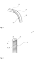
- a suitable choke profile 10,11 in a first embodiment for the cavity assembly 1 according to Fig. 2 and Fig. 3 is shown in a sectional perspective view.
- the rounded choke profile 11 has a fixed shape, so that no adjustment is necessary during assembly (in-situ).
- a straight choke profile 10 and a rounded choke profile 11 are formed separately from each other (regardless of the embodiment of the rounded choke profile 11).
- a suitable choke profile 10,11 in a second embodiment for the cavity assembly 1 according to Fig. 2 and Fig. 3 is shown in a sectional perspective view.
- the rounded choke profile 11 has an adaptable shape so that, although an adjustment may be necessary during assembly (in-situ), a more precise adjustment and/or a use of the rounded choke profile 11 for a larger number of different corner sections 15 (cf. Fig. 3 ) is applicable.
- a straight choke profile 10 and a rounded choke profile 11 are integrally formed with each other, preferably formed from a single sheet or formed from a single extruded profile.
- the rounded choke profile 11 differs from the straight choke profile 10 (cf. Fig. 2 ) primarily in that a plurality of tongues 16 are formed, in this case on the side of the contact tab 19, which are each spaced from one another by a tongue-gap 17, of which a single tongue 16 is designated here pars-prototo with the respective adjacent tongue-gaps 17.
- a tongue-gap 17 of which a single tongue 16 is designated here pars-prototo with the respective adjacent tongue-gaps 17.
- a rounded choke profile 11 according to Fig. 5 is shown separately in a sectional view as it is shown in use in the following Fig. 7 .
- This rounded choke profile 11 comprises a plurality of tongues 16, each of which is separated from the other using tongue-gaps 17 in such a way that the tongues 16 do not overlap each other in the (rounded) form shown.
- a rounded choke profile 11 is adaptable to different radii. In one embodiment, only exactly one shape, for example with a constant rounding radius, can thus be formed, with the tongue-gaps 17 being just evenly closed at least in the region of overlap of the gap 12.
- the property described below is preferably also present in an embodiment without these tongues 16 and tongue-gaps 17, for example as shown in Fig. 4 .
- the rounded choke profile 11 is designed as a U-profile and a guide surface 18 is formed on the side of the frame-side flange 9, by means of which a planar contact with the frame-side flange 9 is formed (cf. Fig. 7 ).
- a contact tab 19 is formed on the cavity-side flange 8, which forms a bend at which a contact line 20 to the cavity-side flange 8 is formed (cf. Fig. 7 ). It should be noted again that the contact tongue 19 is not necessarily formed from a plurality of separated tongues 16.
- a mounting widening 21 is provided on both sides, which facilitates the assembly of the choke profile 11.
- the choke profile 11 is designed with an undersize so that the choke profile 11, preferably purely elastically, is deformed in use (cf. Fig. 7 ) and thus a contact force is exerted for a desired friction locking for self-retaining securing of the choke profile 11.
- Fig. 7 shows a sectional view of a corner portion 15 of a cavity assembly 1.
- the front frame 7 and the cavity member 5 each have a flange 8,9, which extend towards the rear side 4 (here on the left in the illustration) and parallel to each other and preferably parallel to an insertion direction.
- Both the cavity-side flange 8 and the frame-side flange 9 are embraced by the (rounded) choke profile 11 and thus a gap 12 present between the two flanges 8,9 is blocked against penetration of microwave radiation.
- a gasket element 13 can be seen here in the picture, which is inserted from the front side 3 into the gap 12 and fixed by means of a barbed hook 31, here in cooperation with the cavity-side flange 8, and, thus, is secured in a self-retaining manner.
- the gasket element 13 is set up for gasketing closure of the interior space in the cavity member 5 together with a door 22 (cf. Fig. 1 ).
- a fastening element 30 for screwing to the cavity member 5 can be seen here in extension of the frame-side flange 9.
- the detail shown is a detail of a cavity assembly 1, as shown in Fig. 2 .
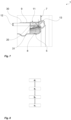
- Fig. 8 shows a flow diagram of an assembly process for a cavity assembly 1.
- the cavity member 5 and the front frame 7 are already provided with a surface treatment.
- the cavity member 5 is already single or double enamelled and the front frame 7 is also single or double enamelled, preferably in independent process steps.
- step a. following step d., the cavity member 5 and the front frame 7 and the required number of choke profiles 10,11, as well as possibly further elements such as screws and/or rivets, are provided for a respective cavity assembly 1. It should be noted that the provision in step a. does not have to take place simultaneously and that at least one of the choke profiles 10,11 is not provided until step c., for example.
- step b. the front frame 7 and the cavity member 5 are aligned with respect to each other so that the front frame 7 is connectable to the cavity member 5 at the frontal opening 6.
- step c. the at least one choke profile 10,11 is applied to the two flanges 8,9 such that the choke profile 10,11 is adapted to block microwave radiation in operation of the oven 2 in which the cavity assembly 1 is mounted, as described above.
- control electronics can be effectively protected from microwave radiation.
Landscapes
- Physics & Mathematics (AREA)
- Electromagnetism (AREA)
- Electric Ovens (AREA)
Claims (15)
- Ensemble cavité (1) pour un four (2) ayant une fonction de chauffage à micro-ondes pour chauffer un comestible,l'ensemble cavité (1) ayant un côté avant (3) et un côté arrière (4), le côté avant (3) étant le côté accessible en utilisation,l'ensemble cavité (1) comprenant au moins les composants suivants :- un élément de cavité (5) ayant vers le côté avant (3) une ouverture frontale (6) pour recevoir un comestible ; et- un cadre avant (7) raccordé à l'élément de cavité (5) au niveau de l'ouverture frontale (6),l'élément de cavité (5) comprenant une bride côté cavité (8) au niveau de l'ouverture frontale (6) et le cadre avant (7) comprenant une bride côté cadre (9), les brides (8, 9) s'étendant vers le côté arrière (4),caractérisé en ce que les deux brides (8, 9) sont encastrées, au moins par sections, au moyen d'au moins un profilé à piège (10, 11) commun, le profilé à piège (10, 11) étant configuré pour bloquer un rayonnement micro-ondes.
- Ensemble cavité (1) selon la revendication 1, dans lequel un espace (12) est formé entre les deux brides (8, 9) au moins par sections,l'espace (12) étant couvert au moins par sections au niveau de l'arrière par le profilé à piège (10, 11),les deux brides (8, 9) étant préférablement alignées parallèlement l'une à l'autre.
- Ensemble cavité (1) selon la revendication 2, dans lequel l'espace (12) vers le côté avant (3) est fermé au moins par sections par un élément de joint d'étanchéité (13).
- Ensemble cavité (1) selon l'une quelconque des revendications précédentes, dans lequel
le profilé à piège (11) a une pluralité de languettes (16) s'étendant de manière unidirectionnelle, les languettes (16) ayant préférablement chacune un espace (17) de languettes, plus préférablement cunéiforme, l'une par rapport à l'autre. - Ensemble cavité (1) selon l'une quelconque des revendications précédentes, dans lequel
ledit profilé à piège (10, 11) est en métal, préférablement en acier inoxydable. - Ensemble cavité (1) selon l'une quelconque des revendications précédentes, dans lequel
le profilé à piège (10, 11) pour encastrer les deux brides (8, 9) a une sous-dimension au moins élastique relativement aux deux brides (8, 9) à encastrer. - Ensemble cavité (1) selon l'une quelconque des revendications précédentes, dans lequel
le profilé à piège (10, 11) a une surface de guidage (18) pour un contact zonal avec l'une des deux brides (8) et, de plus, a une patte de contact (19) qui est construite pour former une ligne de contact (20) avec l'autre bride (9) respective. - Ensemble cavité (1) selon l'une quelconque des revendications précédentes, dans lequel
le profilé à piège (10, 11) a un élargissement de montage (21) sur son côté avant. - Ensemble cavité (1) selon l'une quelconque des revendications précédentes, dans lequel
un profilé à piège droit (10) pour une portion droite (14) de l'élément de cavité (5) et/ou du cadre avant (7) et un profilé à piège arrondi (11) pour une portion de coin (15) de l'élément de cavité (5) et du cadre avant (7) sont d'un seul tenant. - Ensemble cavité (1) selon l'une quelconque des revendications précédentes, dans lequel
le profilé à piège (10, 11) est fixé à l'élément de cavité (5) et au cadre avant (7) au moyen d'au moins l'un des verrouillages suivants :- verrouillage par friction ;- verrouillage positif ; et- verrouillage matériel. - Ensemble cavité (1) selon l'une quelconque des revendications précédentes, dans lequel
ledit élément de cavité (5) et ledit cadre avant (7) sont raccordés de manière détachable non destructrice l'un à l'autre. - Ensemble cavité (1) selon l'une quelconque des revendications précédentes, dans lequel
ledit élément de cavité (5) est à émail double et ledit cadre avant (7) est à émail simple. - Procédé d'assemblage pour un ensemble cavité (1) selon l'une quelconque des revendications précédentes, comprenant les étapes suivantes consistant à :a. fournir l'élément de cavité (5), le cadre avant (7) et l'au moins un profilé à piège (10, 11) ;b. après l'étape a., aligner le cadre avant (7) avec l'élément de cavité (5) au niveau de l'ouverture frontale (6) de l'élément de cavité (5) ; etc. après l'étape b., appliquer l'au moins un profilé à piège (10, 11) sur les deux brides (8, 9) de l'élément de cavité (5) et du cadre avant (7) de sorte que les deux brides (8, 9) soient encastrées.
- Procédé d'assemblage selon la revendication 13, dans lequel
à une étape d. avant l'étape a., l'élément de cavité (5) et le cadre avant (7) ont été traités en surface finale. - Four (2) à fonction de chauffage à micro-ondes pour chauffer un comestible, comprenant au moins les composants suivants :- un ensemble cavité (1) selon l'une quelconque des revendications 1 à 12 ;- une porte (22) au moyen de laquelle, en coopération avec le cadre avant (7), l'ouverture frontale (6) de l'ensemble cavité (1) peut être fermée ;- une source de micro-ondes (23) pour fournir un rayonnement micro-ondes afin de chauffer un comestible situé à l'intérieur de l'élément de cavité (5) ;- de l'électronique de commande (24) pour commander des fonctions du four (2) ;- une connexion d'alimentation (25) pour la source de micro-ondes (23) ; et- une interface d'actionnement (26) pour actionner des fonctions du four (2),dans lequel l'au moins un profilé à piège (10, 11) est agencé pour protéger l'électronique de commande (24) contre un rayonnement micro-ondes,le four (2) comprenant préférablement une source de vapeur qui est configurée pour cuire à la vapeur un comestible qui est situé à l'intérieur de l'élément de cavité (5).
Priority Applications (2)
| Application Number | Priority Date | Filing Date | Title |
|---|---|---|---|
| EP22171043.7A EP4271132B1 (fr) | 2022-04-29 | 2022-04-29 | Ensemble cavité de four avec fonction de chauffage à micro-ondes pour chauffer un comestible |
| PCT/EP2023/059661 WO2023208595A1 (fr) | 2022-04-29 | 2023-04-13 | Ensemble cavité pour four à fonction de chauffage par micro-ondes pour chauffer un produit comestible |
Applications Claiming Priority (1)
| Application Number | Priority Date | Filing Date | Title |
|---|---|---|---|
| EP22171043.7A EP4271132B1 (fr) | 2022-04-29 | 2022-04-29 | Ensemble cavité de four avec fonction de chauffage à micro-ondes pour chauffer un comestible |
Publications (2)
| Publication Number | Publication Date |
|---|---|
| EP4271132A1 EP4271132A1 (fr) | 2023-11-01 |
| EP4271132B1 true EP4271132B1 (fr) | 2025-02-26 |
Family
ID=81454735
Family Applications (1)
| Application Number | Title | Priority Date | Filing Date |
|---|---|---|---|
| EP22171043.7A Active EP4271132B1 (fr) | 2022-04-29 | 2022-04-29 | Ensemble cavité de four avec fonction de chauffage à micro-ondes pour chauffer un comestible |
Country Status (2)
| Country | Link |
|---|---|
| EP (1) | EP4271132B1 (fr) |
| WO (1) | WO2023208595A1 (fr) |
Family Cites Families (3)
| Publication number | Priority date | Publication date | Assignee | Title |
|---|---|---|---|---|
| JPS4939571B1 (fr) * | 1970-04-23 | 1974-10-26 | ||
| JP2503510Y2 (ja) * | 1993-08-03 | 1996-07-03 | 株式会社エイチイーシー | 電磁波シ―ルドル―ム用扉のシ―ル構造 |
| EP2775794B1 (fr) * | 2013-03-04 | 2018-12-26 | Electrolux Appliances Aktiebolag | Porte pour appareil à micro-ondes |
-
2022
- 2022-04-29 EP EP22171043.7A patent/EP4271132B1/fr active Active
-
2023
- 2023-04-13 WO PCT/EP2023/059661 patent/WO2023208595A1/fr not_active Ceased
Also Published As
| Publication number | Publication date |
|---|---|
| EP4271132A1 (fr) | 2023-11-01 |
| WO2023208595A1 (fr) | 2023-11-02 |
Similar Documents
| Publication | Publication Date | Title |
|---|---|---|
| EP3421888B1 (fr) | Appareil de cuisson | |
| US6172338B1 (en) | Cooling system for a cooking appliance | |
| EP3940296B1 (fr) | Appareil de cuisson | |
| CA2910890C (fr) | Electromenager comportant un espace d'air isolant | |
| EP3412975A1 (fr) | Appareil de cuisson | |
| EP4271132A1 (fr) | Ensemble cavité de four avec fonction de chauffage à micro-ondes pour chauffer un comestible | |
| CA1232332A (fr) | Porte de four a micro-ondes | |
| KR20220009904A (ko) | 음식 오븐 | |
| CA2257144C (fr) | Appareil de cuisson a haute frequence et son procede de fabrication | |
| US6446582B1 (en) | Fuel feedline and vapor barrier assembly | |
| EP4543143A1 (fr) | Porte de four pour un four ménager avec fonction de chauffage par micro-ondes | |
| KR100774503B1 (ko) | 전자 레인지 | |
| CN213901151U (zh) | 灶具 | |
| EP0131324A2 (fr) | Procédé pour la fabrication des portes pour fourneaux qui combinent le chauffage à micro-ondes et à résistance électrique | |
| TR2024005769A2 (tr) | Bir Bağlantı Sistemi. | |
| EP3182019B1 (fr) | Appareil de cuisson ayant un élément de couplage | |
| CN219713434U (zh) | 壳体组件和烹饪器具 | |
| TR2023011321A1 (tr) | Görsel yüzeyde emaye kırılmasını engelleyen fırın menteşe bağlantısı. | |
| EP4276366B1 (fr) | Four à fonction de cuisson à la vapeur | |
| KR102965633B1 (ko) | 조리기기 | |
| EP4563895A1 (fr) | Appareil de cuisson | |
| JP3013307U (ja) | ガス器具設置用防熱板 | |
| GB2195760A (en) | Muffle insulation in a cooker | |
| KR20230061211A (ko) | 조리기기 | |
| EP3800401A1 (fr) | Dispositif de cuisson |
Legal Events
| Date | Code | Title | Description |
|---|---|---|---|
| PUAI | Public reference made under article 153(3) epc to a published international application that has entered the european phase |
Free format text: ORIGINAL CODE: 0009012 |
|
| STAA | Information on the status of an ep patent application or granted ep patent |
Free format text: STATUS: THE APPLICATION HAS BEEN PUBLISHED |
|
| AK | Designated contracting states |
Kind code of ref document: A1 Designated state(s): AL AT BE BG CH CY CZ DE DK EE ES FI FR GB GR HR HU IE IS IT LI LT LU LV MC MK MT NL NO PL PT RO RS SE SI SK SM TR |
|
| STAA | Information on the status of an ep patent application or granted ep patent |
Free format text: STATUS: REQUEST FOR EXAMINATION WAS MADE |
|
| 17P | Request for examination filed |
Effective date: 20240502 |
|
| RBV | Designated contracting states (corrected) |
Designated state(s): AL AT BE BG CH CY CZ DE DK EE ES FI FR GB GR HR HU IE IS IT LI LT LU LV MC MK MT NL NO PL PT RO RS SE SI SK SM TR |
|
| GRAP | Despatch of communication of intention to grant a patent |
Free format text: ORIGINAL CODE: EPIDOSNIGR1 |
|
| STAA | Information on the status of an ep patent application or granted ep patent |
Free format text: STATUS: GRANT OF PATENT IS INTENDED |
|
| INTG | Intention to grant announced |
Effective date: 20240924 |
|
| P01 | Opt-out of the competence of the unified patent court (upc) registered |
Free format text: CASE NUMBER: APP_56385/2024 Effective date: 20241016 |
|
| GRAS | Grant fee paid |
Free format text: ORIGINAL CODE: EPIDOSNIGR3 |
|
| GRAA | (expected) grant |
Free format text: ORIGINAL CODE: 0009210 |
|
| STAA | Information on the status of an ep patent application or granted ep patent |
Free format text: STATUS: THE PATENT HAS BEEN GRANTED |
|
| AK | Designated contracting states |
Kind code of ref document: B1 Designated state(s): AL AT BE BG CH CY CZ DE DK EE ES FI FR GB GR HR HU IE IS IT LI LT LU LV MC MK MT NL NO PL PT RO RS SE SI SK SM TR |
|
| REG | Reference to a national code |
Ref country code: GB Ref legal event code: FG4D |
|
| REG | Reference to a national code |
Ref country code: CH Ref legal event code: EP |
|
| REG | Reference to a national code |
Ref country code: DE Ref legal event code: R096 Ref document number: 602022010992 Country of ref document: DE |
|
| REG | Reference to a national code |
Ref country code: IE Ref legal event code: FG4D |
|
| PGFP | Annual fee paid to national office [announced via postgrant information from national office to epo] |
Ref country code: NL Payment date: 20250424 Year of fee payment: 4 |
|
| REG | Reference to a national code |
Ref country code: NL Ref legal event code: FP |
|
| PG25 | Lapsed in a contracting state [announced via postgrant information from national office to epo] |
Ref country code: RS Free format text: LAPSE BECAUSE OF FAILURE TO SUBMIT A TRANSLATION OF THE DESCRIPTION OR TO PAY THE FEE WITHIN THE PRESCRIBED TIME-LIMIT Effective date: 20250526 |
|
| PG25 | Lapsed in a contracting state [announced via postgrant information from national office to epo] |
Ref country code: FI Free format text: LAPSE BECAUSE OF FAILURE TO SUBMIT A TRANSLATION OF THE DESCRIPTION OR TO PAY THE FEE WITHIN THE PRESCRIBED TIME-LIMIT Effective date: 20250226 |
|
| PG25 | Lapsed in a contracting state [announced via postgrant information from national office to epo] |
Ref country code: PL Free format text: LAPSE BECAUSE OF FAILURE TO SUBMIT A TRANSLATION OF THE DESCRIPTION OR TO PAY THE FEE WITHIN THE PRESCRIBED TIME-LIMIT Effective date: 20250226 |
|
| PGFP | Annual fee paid to national office [announced via postgrant information from national office to epo] |
Ref country code: DE Payment date: 20250428 Year of fee payment: 4 |
|
| PG25 | Lapsed in a contracting state [announced via postgrant information from national office to epo] |
Ref country code: ES Free format text: LAPSE BECAUSE OF FAILURE TO SUBMIT A TRANSLATION OF THE DESCRIPTION OR TO PAY THE FEE WITHIN THE PRESCRIBED TIME-LIMIT Effective date: 20250226 |
|
| REG | Reference to a national code |
Ref country code: LT Ref legal event code: MG9D |
|
| PG25 | Lapsed in a contracting state [announced via postgrant information from national office to epo] |
Ref country code: NO Free format text: LAPSE BECAUSE OF FAILURE TO SUBMIT A TRANSLATION OF THE DESCRIPTION OR TO PAY THE FEE WITHIN THE PRESCRIBED TIME-LIMIT Effective date: 20250526 Ref country code: IS Free format text: LAPSE BECAUSE OF FAILURE TO SUBMIT A TRANSLATION OF THE DESCRIPTION OR TO PAY THE FEE WITHIN THE PRESCRIBED TIME-LIMIT Effective date: 20250626 |
|
| PG25 | Lapsed in a contracting state [announced via postgrant information from national office to epo] |
Ref country code: HR Free format text: LAPSE BECAUSE OF FAILURE TO SUBMIT A TRANSLATION OF THE DESCRIPTION OR TO PAY THE FEE WITHIN THE PRESCRIBED TIME-LIMIT Effective date: 20250226 |
|
| PG25 | Lapsed in a contracting state [announced via postgrant information from national office to epo] |
Ref country code: PT Free format text: LAPSE BECAUSE OF FAILURE TO SUBMIT A TRANSLATION OF THE DESCRIPTION OR TO PAY THE FEE WITHIN THE PRESCRIBED TIME-LIMIT Effective date: 20250626 Ref country code: LV Free format text: LAPSE BECAUSE OF FAILURE TO SUBMIT A TRANSLATION OF THE DESCRIPTION OR TO PAY THE FEE WITHIN THE PRESCRIBED TIME-LIMIT Effective date: 20250226 |
|
| PG25 | Lapsed in a contracting state [announced via postgrant information from national office to epo] |
Ref country code: BG Free format text: LAPSE BECAUSE OF FAILURE TO SUBMIT A TRANSLATION OF THE DESCRIPTION OR TO PAY THE FEE WITHIN THE PRESCRIBED TIME-LIMIT Effective date: 20250226 Ref country code: GR Free format text: LAPSE BECAUSE OF FAILURE TO SUBMIT A TRANSLATION OF THE DESCRIPTION OR TO PAY THE FEE WITHIN THE PRESCRIBED TIME-LIMIT Effective date: 20250527 |
|
| REG | Reference to a national code |
Ref country code: AT Ref legal event code: MK05 Ref document number: 1771948 Country of ref document: AT Kind code of ref document: T Effective date: 20250226 |
|
| PG25 | Lapsed in a contracting state [announced via postgrant information from national office to epo] |
Ref country code: SE Free format text: LAPSE BECAUSE OF FAILURE TO SUBMIT A TRANSLATION OF THE DESCRIPTION OR TO PAY THE FEE WITHIN THE PRESCRIBED TIME-LIMIT Effective date: 20250226 |
|
| PG25 | Lapsed in a contracting state [announced via postgrant information from national office to epo] |
Ref country code: SM Free format text: LAPSE BECAUSE OF FAILURE TO SUBMIT A TRANSLATION OF THE DESCRIPTION OR TO PAY THE FEE WITHIN THE PRESCRIBED TIME-LIMIT Effective date: 20250226 |
|
| PG25 | Lapsed in a contracting state [announced via postgrant information from national office to epo] |
Ref country code: DK Free format text: LAPSE BECAUSE OF FAILURE TO SUBMIT A TRANSLATION OF THE DESCRIPTION OR TO PAY THE FEE WITHIN THE PRESCRIBED TIME-LIMIT Effective date: 20250226 |
|
| PG25 | Lapsed in a contracting state [announced via postgrant information from national office to epo] |
Ref country code: IT Free format text: LAPSE BECAUSE OF FAILURE TO SUBMIT A TRANSLATION OF THE DESCRIPTION OR TO PAY THE FEE WITHIN THE PRESCRIBED TIME-LIMIT Effective date: 20250226 |
|
| PG25 | Lapsed in a contracting state [announced via postgrant information from national office to epo] |
Ref country code: AT Free format text: LAPSE BECAUSE OF FAILURE TO SUBMIT A TRANSLATION OF THE DESCRIPTION OR TO PAY THE FEE WITHIN THE PRESCRIBED TIME-LIMIT Effective date: 20250226 |
|
| PG25 | Lapsed in a contracting state [announced via postgrant information from national office to epo] |
Ref country code: EE Free format text: LAPSE BECAUSE OF FAILURE TO SUBMIT A TRANSLATION OF THE DESCRIPTION OR TO PAY THE FEE WITHIN THE PRESCRIBED TIME-LIMIT Effective date: 20250226 Ref country code: CZ Free format text: LAPSE BECAUSE OF FAILURE TO SUBMIT A TRANSLATION OF THE DESCRIPTION OR TO PAY THE FEE WITHIN THE PRESCRIBED TIME-LIMIT Effective date: 20250226 |
|
| PG25 | Lapsed in a contracting state [announced via postgrant information from national office to epo] |
Ref country code: RO Free format text: LAPSE BECAUSE OF FAILURE TO SUBMIT A TRANSLATION OF THE DESCRIPTION OR TO PAY THE FEE WITHIN THE PRESCRIBED TIME-LIMIT Effective date: 20250226 |
|
| PG25 | Lapsed in a contracting state [announced via postgrant information from national office to epo] |
Ref country code: SK Free format text: LAPSE BECAUSE OF FAILURE TO SUBMIT A TRANSLATION OF THE DESCRIPTION OR TO PAY THE FEE WITHIN THE PRESCRIBED TIME-LIMIT Effective date: 20250226 |
|
| REG | Reference to a national code |
Ref country code: CH Ref legal event code: H13 Free format text: ST27 STATUS EVENT CODE: U-0-0-H10-H13 (AS PROVIDED BY THE NATIONAL OFFICE) Effective date: 20251125 |
|
| REG | Reference to a national code |
Ref country code: DE Ref legal event code: R097 Ref document number: 602022010992 Country of ref document: DE |
|
| PG25 | Lapsed in a contracting state [announced via postgrant information from national office to epo] |
Ref country code: LU Free format text: LAPSE BECAUSE OF NON-PAYMENT OF DUE FEES Effective date: 20250429 |
|
| PG25 | Lapsed in a contracting state [announced via postgrant information from national office to epo] |
Ref country code: MC Free format text: LAPSE BECAUSE OF FAILURE TO SUBMIT A TRANSLATION OF THE DESCRIPTION OR TO PAY THE FEE WITHIN THE PRESCRIBED TIME-LIMIT Effective date: 20250226 |
|
| REG | Reference to a national code |
Ref country code: BE Ref legal event code: MM Effective date: 20250430 |
|
| PLBE | No opposition filed within time limit |
Free format text: ORIGINAL CODE: 0009261 |
|
| STAA | Information on the status of an ep patent application or granted ep patent |
Free format text: STATUS: NO OPPOSITION FILED WITHIN TIME LIMIT |
|
| PG25 | Lapsed in a contracting state [announced via postgrant information from national office to epo] |
Ref country code: FR Free format text: LAPSE BECAUSE OF NON-PAYMENT OF DUE FEES Effective date: 20250430 |
|
| PG25 | Lapsed in a contracting state [announced via postgrant information from national office to epo] |
Ref country code: BE Free format text: LAPSE BECAUSE OF NON-PAYMENT OF DUE FEES Effective date: 20250430 |
|
| PG25 | Lapsed in a contracting state [announced via postgrant information from national office to epo] |
Ref country code: CH Free format text: LAPSE BECAUSE OF NON-PAYMENT OF DUE FEES Effective date: 20250430 |
|
| 26N | No opposition filed |
Effective date: 20251127 |
|
| PG25 | Lapsed in a contracting state [announced via postgrant information from national office to epo] |
Ref country code: IE Free format text: LAPSE BECAUSE OF NON-PAYMENT OF DUE FEES Effective date: 20250429 |