EP4272964A1 - Tampon de mesure de gouttes d'encre, dispositif d'imprimante à jet d'encre le comprenant et procédé de mesure de gouttes d'encre - Google Patents
Tampon de mesure de gouttes d'encre, dispositif d'imprimante à jet d'encre le comprenant et procédé de mesure de gouttes d'encre Download PDFInfo
- Publication number
- EP4272964A1 EP4272964A1 EP21915419.2A EP21915419A EP4272964A1 EP 4272964 A1 EP4272964 A1 EP 4272964A1 EP 21915419 A EP21915419 A EP 21915419A EP 4272964 A1 EP4272964 A1 EP 4272964A1
- Authority
- EP
- European Patent Office
- Prior art keywords
- pad
- ink drop
- ink
- inkjet
- stage
- Prior art date
- Legal status (The legal status is an assumption and is not a legal conclusion. Google has not performed a legal analysis and makes no representation as to the accuracy of the status listed.)
- Pending
Links
- 238000005259 measurement Methods 0.000 title claims description 103
- 238000000691 measurement method Methods 0.000 title description 5
- 238000000034 method Methods 0.000 claims abstract description 30
- 238000007639 printing Methods 0.000 claims description 57
- 238000012423 maintenance Methods 0.000 claims description 40
- 239000000463 material Substances 0.000 claims description 24
- 230000007480 spreading Effects 0.000 claims description 6
- 238000009281 ultraviolet germicidal irradiation Methods 0.000 claims description 6
- 230000003287 optical effect Effects 0.000 claims description 5
- 239000000758 substrate Substances 0.000 claims description 5
- 230000000694 effects Effects 0.000 claims description 4
- 239000003086 colorant Substances 0.000 claims description 3
- 238000001035 drying Methods 0.000 claims description 3
- 238000000465 moulding Methods 0.000 claims description 3
- 238000005507 spraying Methods 0.000 claims description 3
- 238000004364 calculation method Methods 0.000 claims description 2
- 230000008901 benefit Effects 0.000 abstract description 5
- 238000012545 processing Methods 0.000 abstract description 3
- 238000005516 engineering process Methods 0.000 description 8
- 238000004519 manufacturing process Methods 0.000 description 6
- 238000006243 chemical reaction Methods 0.000 description 3
- 238000007641 inkjet printing Methods 0.000 description 3
- 238000004891 communication Methods 0.000 description 2
- 238000007689 inspection Methods 0.000 description 2
- 239000012780 transparent material Substances 0.000 description 2
- 230000002730 additional effect Effects 0.000 description 1
- 230000015556 catabolic process Effects 0.000 description 1
- 230000008859 change Effects 0.000 description 1
- 238000000576 coating method Methods 0.000 description 1
- 238000012937 correction Methods 0.000 description 1
- 230000007423 decrease Effects 0.000 description 1
- 230000007547 defect Effects 0.000 description 1
- 238000006731 degradation reaction Methods 0.000 description 1
- 230000008021 deposition Effects 0.000 description 1
- 238000013461 design Methods 0.000 description 1
- 238000009713 electroplating Methods 0.000 description 1
- 238000012986 modification Methods 0.000 description 1
- 230000004048 modification Effects 0.000 description 1
- 238000000206 photolithography Methods 0.000 description 1
- 229920000642 polymer Polymers 0.000 description 1
- 239000002096 quantum dot Substances 0.000 description 1
- 230000001360 synchronised effect Effects 0.000 description 1
- 238000012546 transfer Methods 0.000 description 1
Images



Classifications
-
- B—PERFORMING OPERATIONS; TRANSPORTING
- B41—PRINTING; LINING MACHINES; TYPEWRITERS; STAMPS
- B41J—TYPEWRITERS; SELECTIVE PRINTING MECHANISMS, i.e. MECHANISMS PRINTING OTHERWISE THAN FROM A FORME; CORRECTION OF TYPOGRAPHICAL ERRORS
- B41J2/00—Typewriters or selective printing mechanisms characterised by the printing or marking process for which they are designed
- B41J2/005—Typewriters or selective printing mechanisms characterised by the printing or marking process for which they are designed characterised by bringing liquid or particles selectively into contact with a printing material
- B41J2/01—Ink jet
- B41J2/21—Ink jet for multi-colour printing
- B41J2/2132—Print quality control characterised by dot disposition, e.g. for reducing white stripes or banding
- B41J2/2142—Detection of malfunctioning nozzles
-
- B—PERFORMING OPERATIONS; TRANSPORTING
- B41—PRINTING; LINING MACHINES; TYPEWRITERS; STAMPS
- B41J—TYPEWRITERS; SELECTIVE PRINTING MECHANISMS, i.e. MECHANISMS PRINTING OTHERWISE THAN FROM A FORME; CORRECTION OF TYPOGRAPHICAL ERRORS
- B41J2/00—Typewriters or selective printing mechanisms characterised by the printing or marking process for which they are designed
- B41J2/005—Typewriters or selective printing mechanisms characterised by the printing or marking process for which they are designed characterised by bringing liquid or particles selectively into contact with a printing material
- B41J2/01—Ink jet
- B41J2/015—Ink jet characterised by the jet generation process
- B41J2/04—Ink jet characterised by the jet generation process generating single droplets or particles on demand
- B41J2/045—Ink jet characterised by the jet generation process generating single droplets or particles on demand by pressure, e.g. electromechanical transducers
- B41J2/04501—Control methods or devices therefor, e.g. driver circuits, control circuits
- B41J2/0456—Control methods or devices therefor, e.g. driver circuits, control circuits detecting drop size, volume or weight
-
- B—PERFORMING OPERATIONS; TRANSPORTING
- B41—PRINTING; LINING MACHINES; TYPEWRITERS; STAMPS
- B41J—TYPEWRITERS; SELECTIVE PRINTING MECHANISMS, i.e. MECHANISMS PRINTING OTHERWISE THAN FROM A FORME; CORRECTION OF TYPOGRAPHICAL ERRORS
- B41J11/00—Devices or arrangements of selective printing mechanisms, e.g. ink-jet printers or thermal printers, for supporting or handling copy material in sheet or web form
- B41J11/0015—Devices or arrangements of selective printing mechanisms, e.g. ink-jet printers or thermal printers, for supporting or handling copy material in sheet or web form for treating before, during or after printing or for uniform coating or laminating the copy material before or after printing
- B41J11/002—Curing or drying the ink on the copy materials, e.g. by heating or irradiating
- B41J11/0021—Curing or drying the ink on the copy materials, e.g. by heating or irradiating using irradiation
- B41J11/00214—Curing or drying the ink on the copy materials, e.g. by heating or irradiating using irradiation using UV radiation
-
- B—PERFORMING OPERATIONS; TRANSPORTING
- B41—PRINTING; LINING MACHINES; TYPEWRITERS; STAMPS
- B41J—TYPEWRITERS; SELECTIVE PRINTING MECHANISMS, i.e. MECHANISMS PRINTING OTHERWISE THAN FROM A FORME; CORRECTION OF TYPOGRAPHICAL ERRORS
- B41J2/00—Typewriters or selective printing mechanisms characterised by the printing or marking process for which they are designed
- B41J2/005—Typewriters or selective printing mechanisms characterised by the printing or marking process for which they are designed characterised by bringing liquid or particles selectively into contact with a printing material
- B41J2/01—Ink jet
- B41J2/015—Ink jet characterised by the jet generation process
- B41J2/04—Ink jet characterised by the jet generation process generating single droplets or particles on demand
- B41J2/045—Ink jet characterised by the jet generation process generating single droplets or particles on demand by pressure, e.g. electromechanical transducers
- B41J2/04501—Control methods or devices therefor, e.g. driver circuits, control circuits
- B41J2/04535—Control methods or devices therefor, e.g. driver circuits, control circuits involving calculation of drop size, weight or volume
-
- B—PERFORMING OPERATIONS; TRANSPORTING
- B41—PRINTING; LINING MACHINES; TYPEWRITERS; STAMPS
- B41J—TYPEWRITERS; SELECTIVE PRINTING MECHANISMS, i.e. MECHANISMS PRINTING OTHERWISE THAN FROM A FORME; CORRECTION OF TYPOGRAPHICAL ERRORS
- B41J2/00—Typewriters or selective printing mechanisms characterised by the printing or marking process for which they are designed
- B41J2/005—Typewriters or selective printing mechanisms characterised by the printing or marking process for which they are designed characterised by bringing liquid or particles selectively into contact with a printing material
- B41J2/01—Ink jet
- B41J2/015—Ink jet characterised by the jet generation process
- B41J2/04—Ink jet characterised by the jet generation process generating single droplets or particles on demand
- B41J2/045—Ink jet characterised by the jet generation process generating single droplets or particles on demand by pressure, e.g. electromechanical transducers
- B41J2/04501—Control methods or devices therefor, e.g. driver circuits, control circuits
- B41J2/04571—Control methods or devices therefor, e.g. driver circuits, control circuits detecting viscosity
-
- B—PERFORMING OPERATIONS; TRANSPORTING
- B41—PRINTING; LINING MACHINES; TYPEWRITERS; STAMPS
- B41J—TYPEWRITERS; SELECTIVE PRINTING MECHANISMS, i.e. MECHANISMS PRINTING OTHERWISE THAN FROM A FORME; CORRECTION OF TYPOGRAPHICAL ERRORS
- B41J2/00—Typewriters or selective printing mechanisms characterised by the printing or marking process for which they are designed
- B41J2/005—Typewriters or selective printing mechanisms characterised by the printing or marking process for which they are designed characterised by bringing liquid or particles selectively into contact with a printing material
- B41J2/01—Ink jet
- B41J2/135—Nozzles
- B41J2/165—Prevention or detection of nozzle clogging, e.g. cleaning, capping or moistening for nozzles
- B41J2/16579—Detection means therefor, e.g. for nozzle clogging
-
- G—PHYSICS
- G01—MEASURING; TESTING
- G01N—INVESTIGATING OR ANALYSING MATERIALS BY DETERMINING THEIR CHEMICAL OR PHYSICAL PROPERTIES
- G01N21/00—Investigating or analysing materials by the use of optical means, i.e. using sub-millimetre waves, infrared, visible or ultraviolet light
- G01N21/84—Systems specially adapted for particular applications
- G01N21/88—Investigating the presence of flaws or contamination
-
- G—PHYSICS
- G01—MEASURING; TESTING
- G01N—INVESTIGATING OR ANALYSING MATERIALS BY DETERMINING THEIR CHEMICAL OR PHYSICAL PROPERTIES
- G01N21/00—Investigating or analysing materials by the use of optical means, i.e. using sub-millimetre waves, infrared, visible or ultraviolet light
- G01N21/84—Systems specially adapted for particular applications
- G01N21/88—Investigating the presence of flaws or contamination
- G01N21/89—Investigating the presence of flaws or contamination in moving material, e.g. running paper or textiles
-
- G—PHYSICS
- G03—PHOTOGRAPHY; CINEMATOGRAPHY; ANALOGOUS TECHNIQUES USING WAVES OTHER THAN OPTICAL WAVES; ELECTROGRAPHY; HOLOGRAPHY
- G03F—PHOTOMECHANICAL PRODUCTION OF TEXTURED OR PATTERNED SURFACES, e.g. FOR PRINTING, FOR PROCESSING OF SEMICONDUCTOR DEVICES; MATERIALS THEREFOR; ORIGINALS THEREFOR; APPARATUS SPECIALLY ADAPTED THEREFOR
- G03F9/00—Registration or positioning of originals, masks, frames, photographic sheets or textured or patterned surfaces, e.g. automatically
- G03F9/70—Registration or positioning of originals, masks, frames, photographic sheets or textured or patterned surfaces, e.g. automatically for microlithography
- G03F9/7003—Alignment type or strategy, e.g. leveling, global alignment
- G03F9/7042—Alignment for lithographic apparatus using patterning methods other than those involving the exposure to radiation, e.g. by stamping or imprinting
Definitions
- the present invention relates to measurement of an ink drop, and more particularly, to a measurement pad capable of easily measuring a volume and a position of an ink drop, a measurement method using same, and an inkjet printer device.
- a technology using the strobe technology in which a digital camera, optical device, and LED lighting device are installed on both side surfaces of an inkjet head on a linear line in accordance with a height of the head, and an ink drop ejection time and flickering of the LED lighting device are synchronized to produce an image that seems to show one ink drop as if ink drops ejected onto a screen are stopped at one position during flight.
- this method has a biggest problem in that an ink drop of a still image seen at a high ejection frequency is not an image of one ink drop, but an image of a plurality of overlapped ink drops with position errors and size errors according to the ejection frequency.
- this method inevitably has a large measurement error due to a shape of the ink drop, straightness of the ink drop, a strobe error, an error of a plurality of substantial ink drops, a difference in lighting, and a recognition method and error (limited resolution) of a vision recognition technology.
- this method has a problem in that a position accuracy of ink drops ejected in front or rear directions of the camera may not be measured, a position accuracy of ink drops ejected in left and right directions is difficult to be measured, and additional time is required.
- the present invention provides a method for quickly and accurately processing a volume and a position of an ink drop in order to solve the above problem.
- an embodiment of the present invention provides an ink drop measurement pad for measuring volumes and positions of inkjet drops that are sprayed and dropped in a constant volume from nozzles of a head of an inkjet device, the ink drop measurement pad including a pattern part including a plurality of groove portions arranged at pitch intervals corresponding to those of a plurality of head nozzles and wall portions formed between the groove portions, and the groove portions are uniformly formed so as to have the same cross-section throughout an entire longitudinal direction thereof.
- the pattern part may be formed in the same direction as a printing direction or a direction perpendicular to the printing direction.
- the pattern part may be formed such that the pattern part formed in the same direction as the printing direction and the pattern part formed in the direction perpendicular to the printing direction are simultaneously formed in one pad.
- the groove portion may be made of a lyophilic material
- an upper wall portion of the wall portion may be made of a lyophobic material
- a side wall portion of the wall portion may be made of the lyophilic or lyophobic material.
- the groove portion may be coated with a lyophilic material
- an upper wall portion of the wall portion may be coated with a lyophobic material
- a side wall portion of the wall portion may be coated with the lyophilic or lyophobic material.
- a width, and a depth of the groove portion in the pattern part may be formed to realize: an ink property related to ink spreading characteristics such as viscosity, surface tension, drying characteristics, and polarity of ink; and sufficient ink drop spreading required for a measurement precision depending on a cross-sectional shape of the groove portion and a surface state such as surface tension and roughness of a bottom surface of the groove portion.
- the pad may have a flat sheet shape.
- the pad may have a roll shape so that the pad is continuously supplied with a width corresponding to that of the inkjet head and a predetermined length and removed from the inkjet device.
- the pad may have a transparent color different from a color of the ink.
- the groove portion and the wall portion may have different colors from each other.
- an inkjet device including the ink drop measurement pad includes: an inkjet printer unit; and a head maintenance unit installed in parallel to the inkjet printer unit, the inkjet printer unit includes: a Y1 stage on which an object b1 to be printed is disposed and which is movable in a Y-direction; and a X1 stage installed higher than a height of the obj ect b 1 to be printed and extending to be movable until a Y2 stage of the head maintenance unit in an X-direction, and the head maintenance unit includes: a Y2 stage installed in parallel to the Y1 stage and movable in the Y-direction; a plate device installed on the Y2 stage to fix the ink drop measurement pad; and an ink drop measurement device installed on the head maintenance unit to measure a length and a position of each ink drop dropped onto the pad.
- an X2 stage may be additionally installed on the head maintenance unit to be movable in the X-direction, and an ink removal device configured to remove the ink drop dropped onto the pad may be installed on the X2 stage.
- a roll supply device configured to continuously supply the ink drop measurement pad to the plate device in a roll manner may be additionally installed on the head maintenance unit.
- the ink removal device may include a vacuum suction device configured to suction the ink drops.
- the ink removal device may include an UV irradiation device configured to cure the ink drops.
- a method for measuring ink drops which measures ink drops sprayed and dropped from an inkjet head of an inkjet device, includes: a step s100 of supplying an ink drop measurement pad in which a plurality of groove portions are formed with an interval corresponding to a nozzle pitch of an inkjet device and have uniform cross-sections throughout an entire longitudinal direction and supporting the ink drop measurement pad by a plate; a step s200 of arranging the ink drop measurement pad supported in the step s100 below the inkjet head while aligning the groove portion to be positioned perpendicularly below a nozzle; a step s300 of spraying ink drops from the nozzle toward the pad arranged in the step s200 and dropping the ink drops into the groove portions; and a step s400 of measuring a deviation of a length and a central position of each ink drop dropped in the step s300 by using an ink drop measurement device.
- the length of the ink drop dropped onto the pad p may be measured by the ink drop measurement device to measure a volume of the ink drop.
- a central position c1 of the ink drop dropped onto the pad p may be measured by the ink drop measurement device, the measured central position c1 may be compared with a reference central position c of each ink drop determined by an alignment mark formed on a corner of the pad, and a position deviation e ( ⁇ x, ⁇ y) therebetween may be measured.
- step s400 by measuring the ink drop dropped onto the pad p, existence of the ink drop may be measured to determine whether the ink drop is ejected from all nozzles of the initial inkjet head after installing the inkjet printer, thereby analyzing an insufficient air removal state or a nozzle clogging state of each nozzle.
- the volume of the ink drop dropped onto the pad p may be measured to calculate the volume ejected from the specific nozzle, and one or a plurality of voltage waveforms may be set in one nozzle for achieving a target volume of the ink drop by ejecting a plurality of ink drops at the same position of the pad p by using the calculated result.
- a volume ejected from each nozzle may be calculated by measuring the volume of the ink drop dropped onto the pad p, and a combination of a plurality of nozzles may be set to achieve a target volume of the ink drop by ejecting a plurality of ink drops at the same position of the pad p using the calculation result
- the volume and position of the ink drop dropped onto the pad p reflecting an effect of crosstalk between the nozzles of the inkjet head may be measured, and the position and volume of each nozzle may be compensated to avoid the crosstalk between the nozzles by using the measured result
- a step (s500) of removing the ink drop dropped onto the pad may be performed after the step (s400) is finished.
- an imprint device including the ink drop measurement pad includes: an imprint device unit; and a head maintenance unit installed in parallel to the imprint device unit, the imprint device unit includes: an X3 stage on which a work holder wh on which an object b2 to be imprinted such as a substrate is disposed is movable in an X-axis direction; a Y3 stage allowing the X3 stage to be movable in a Y-axis direction; a X4 stage extending so that the inkjet head h is installed higher than a height of the object b2 to be imprinted and movable until a Y2 stage of the head maintenance unit in the X-axis direction; a mold driving unit configured to hold and support a mold m that performs imprinting, correct a shape of the mold with the object to be imprinted, and perform a stamping operation; an optical device configured to align a mark of the object b2 to be imprinted with a mark of the mold m
- an X2 stage may be additionally installed on the head maintenance unit to be moved in the X-direction, and an ink removal device configured to remove the ink drop dropped onto the pad may be installed on the X2 stage.
- a roll supply device configured to continuously supply the ink drop measurement pad in a roll manner to the plate device may be additionally installed on the head maintenance unit.
- the ink removal device may include a vacuum suction device configured to suction the ink drops.
- the ink removal device may include an UV irradiation device configured to cure the ink drops.
- the present invention has the advantage that the volumes and positions of ink drops may be accurately measured using the pad to a precision of 1% or less much more simply and quickly in the inkjet printer device than the existing techniques that use a strobe.
- the ink drop dropped onto the pad p is measured by using the above-described feature, whether the ink drop exists may be measured to determine whether ink drops are ejected from all nozzles of the initial inkjet head after the inkjet printer is installed, and the insufficient air removal state or the nozzle clogging state of each nozzle may be identified to implement additional action to solve the nozzle clogging or appropriately compensate for the nozzle clogging.
- the volume ejected from the specific nozzle may be calculated by measuring the volume of the ink drops dropped onto the pad p.
- the setting of one or the plurality of voltage waveforms in one nozzle for achieving the target volumes of the ink drops by ejecting the plurality of ink drops at the same position of the pad p may quickly and easily performed.
- the volume ejected from the specific nozzle may be calculated by measuring the volume of the ink drops dropped onto the pad p.
- the inkjet printer device may perform the operation of ejecting the predetermined ink drops from the predetermined nozzles according to the pattern information required for each nozzle.
- the sound waves generated when each nozzle ejects cause the crosstalk by which the ejection speed of the ink drops of the surrounding nozzles is reduced and the volume thereof is also reduced when the nozzle ejects the ink drops.
- the nozzle may be easily compensated to prevent the crosstalk by measuring the volume and position of the ink drop dropped onto the pad p.
- the present invention may quickly and easily measure the position error of the ink drops dropped from each nozzle simultaneously with the volume of the ink drops by measuring the positions of the ink drops dropped onto the pad p in the X and Y directions.
- This position error measurement result may be compensated during substantial printing to enable more precise printing.
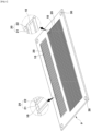
- FIG. 1 is a view illustrating an ink drop measurement pad according to the present invention.
- a pad (p) for measuring ink drops may be formed in a flat sheet or film shape by a photolithography or imprint method.
- the pad p for measuring ink drops includes a plurality of groove portions 10, a plurality of wall portions 20 formed between the groove portions 10, and an alignment mark 30.
- the wall portion 20 includes a side wall portion 21 formed on both sides of the groove portion 10 to protrude upward and an upper wall portion 22 formed on a top surface between the side wall portions 21.
- the alignment mark 30 is formed at each corner of the pad p along a head printing width.
- An interval of the plurality of groove portions 10 is equal to a pitch interval of a nozzle or a multiple or divisor.
- the interval of the groove portions may be a multiple of 600 npi such as 1200 npi, 1800 npi, and 2400 npi or a divisor of 600 npi such as 300 npi, 200 npi, and 100 npi.
- the groove portion 10 may have a length enough to encompass all of the nozzles in arrangement in a transverse direction of a head in an inkjet device.
- the groove portion 10 may have a depth and a width that maintain the same size throughout a longitudinal direction of the groove portion 10.
- the groove portion 10 has a rectangular cross-sectional shape in this embodiment, the present invention is not limited thereto.
- the groove portion 10 may have various shapes such as an inverted triangle or semicircular shape as long as the shape maintains the same cross section throughout the longitudinal direction.
- the width and depth of the groove portion 10 may be determined to realize: an ink property related to ink spreading control characteristics such as viscosity, surface tension, drying characteristics, and polarity of ink to be used; and sufficient ink drop spreading required for measurement precision depending on a surface condition such as surface tension and roughness of a groove and a bottom surface of the groove.
- all of the groove portions 10 formed in the same direction as a printing direction and two groove portions 10 formed in a direction perpendicular to the printing direction are formed in the pad p.
- ink drop dropped position errors in the printing direction and the direction perpendicular to the printing direction of each nozzle may be measured simultaneously.
- the groove portion 10 may be formed in the pad p in the printing direction as illustrated in FIG. 7 or in the direction perpendicular to the printing direction as illustrated in FIG. 8 .
- the ink drop dropped position errors in the printing direction and the direction perpendicular to the printing direction of each nozzle may be measured simultaneously.
- the entire pad p may be made of one material, or the groove portion 10 may be made of a lyophilic material so that ink drops are well accommodated and the wall portion 20 may be made of a lyophobic material.
- the pad p may be made of or coated with a lyophilic material while the side wall portion 21 of the groove portion 10 is made of a lyophobic material, or the pad p may be coated with a lyophilic material while the upper wall portion 22 is made of or coated with a lyophobic material to have a lyophobic property.
- the entire pad p may be made of a transparent material so that the pad p is illuminated from therebelow.
- the groove portion 10 and the wall portion 20 may have different colors so that the groove portion 10 and the wall portion 20 are easily distinguished from each other.
- the groove portion 10 may be made of a transparent material, and the wall portion 20 may have a color so that the groove portion 10 and the wall portion 20 are easily distinguished from each other.
- the pad p may have a flat sheet shape so as to be mounted on a flat plate device of the inkjet device.
- the pad p may have a roll shape having a width corresponding to that of the inkjet head so that the pad p is easily supplied to and removed from the inkjet device and be continuously supplied.
- the pad p may be supplied to the inkjet device in a form of a rectangular sheet or continuously supplied in a form of a roll having a width corresponding to a head width.
- FIG. 2 is a view illustrating an inkjet printer device including an ink drop measurement pad according to the present invention.
- An inkjet printer device D includes an inkjet printer unit 100 and a head maintenance unit 200 installed in parallel to the inkjet printer unit 100.
- the inkjet printer unit 100 includes a Y1 stage 110 including a work holder wh on which an object b1 to be printed such as a substrate is disposed and movable in a Y-direction and a X1 stage 120 extending so that an inkjet head h is installed higher than a height of an object b1 to be printed and the X1 stage 120 is moved until a Y2 stage 210 of the head maintenance unit 200 in an X-direction.
- FIG. 3 is a view illustrating a state in which nozzles are arranged in the inkjet printer device including the ink drop measurement pad according to the present invention.
- a plurality of nozzles n are installed on a bottom surface of the head h and inclined in the transverse direction of the head h.
- arrangement of the nozzles n may be different for each head h instead of being inclined.
- a reason for the inclined arrangement is to insert the nozzles n maximally within a size of the same head h and simultaneously to narrow an interval between the nozzles n, thereby increasing a resolution and connecting the head h continuously on a linear line in the transverse direction.
- the heads h may be arranged in two rows and continuously connected so that the nozzles n are continuously connected at a predetermined pitch in the transverse direction.
- the head maintenance unit 200 includes an Y2 stage 210 installed in parallel to the Y1 stage 110 and movable in the Y direction, a plate device 220 installed on the Y2 stage 210 to arrange the ink drop measurement pad p, and an ink drop measurement device 230.
- the plate device 220 has a flat plate shape, and the measurement pad p is fixed to an upper portion of the plate device 220.
- the plate device 220 may be rotatable to align a direction of the groove portion 10 to the printing direction even when the measurement pad p having the groove portion 10 in the printing direction and in the direction perpendicular to the printing direction is fixed to the plate device 220.
- the pad p may be arranged in the printing direction or in the direction perpendicular to the printing direction.
- a roll supply device 260 may be provided for a case of supplying the pad p in a roll manner.
- tensile force may act in a roll supply direction to stretch the measurement pad p in the roll supply direction, and this limitation may be compensated in real time by measuring a substantial width of each groove portion 10.
- the ink drop measurement device 230 that serves to measure a length and a degree of deviation from a center position of the ink drop dropped in the groove portion 10 of the pad p has a well-known configuration.
- the ink drop measurement device 230 may include any device that is capable of measuring a shape of an ink drop, such as a vision system using a camera, a laser scan device, or an ultrasonic device.
- the head maintenance unit 200 includes an X2 stage 240 that is additionally installed to be movable in the X-direction, and an ink removal device 250 capable of removing ink drops dropped onto the pad p is installed on the X2 stage 240.
- a vacuum suction device 251 capable of suctioning ink drops and/or an UV irradiation device 252 capable of curing ink drops to attach and remove the ink drop to and from the pad p are installed.
- a maintenance device 270 for maintaining the inkjet head is installed on the head maintenance unit 200.
- the inkjet printer unit 100 performs a basic inkjet printing operation in a well-known manner.
- the object b1 to be printed is moved along the Y1 stage 110 and disposed below the inkjet head h, and then ink drops are sprayed to the nozzle of the inkjet head h to perform the printing operation.
- An operation of measuring ink drops by using the ink drop measurement pad according to the present invention is performed by the head maintenance unit 200.
- the inkjet head h is transferred from the inkjet printer unit 100 to the head maintenance unit 200 along the X1 stage 120, and then the operation of measuring ink drops is performed by an ink drop measurement method described later.
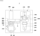
- FIG. 4 is a view illustrating an imprint device including the inkjet printer unit having the ink drop measurement pad according to the present invention.
- An imprint device I including the inkjet printer unit having the ink drop measurement pad according to the present invention includes an imprint device unit 300 and a head maintenance unit 200 installed in parallel to the imprint device unit 300.
- the imprint device unit 300 includes: an X3 stage 310 on which a work holder wh on which an object b2 to be imprinted such as a substrate is disposed is movable in the X-axis direction; a Y3 stage 320 allowing the X3 stage 310 to be movable in the Y-axis direction; a X4 stage 330 extending so that the inkjet head h is installed higher than a height of the object b2 to be imprinted and movable until the Y2 stage 210 of the head maintenance unit 200 in the X-axis direction; a mold driving unit 340 that holds and supports a mold m for performing imprinting, corrects a shape of the mold with the object to be imprinted, and performs a stamping operation; an optical device 350 for aligning a mark of the object b2 to be imprinted with a mark of the mold m; and a curing device 360 for curing an imprint material after molding the object to be imprinted.
- the head maintenance unit 200 in the imprint device I has the same configuration as the above-described head maintenance unit 200 of the inkjet device D, the Y2 stage 210 is installed in parallel to the Y3 stage 310, and the rest of the configuration is the same.
- a basic imprint operation is performed by the imprint device unit 300 in a well-known manner.
- the object b2 to be imprinted is disposed below the inkjet head h through the X3 stage 310 and the Y3 stage 320, and then ink drops made of the imprint material are sprayed from the inkjet head h.
- the object b2 to be imprinted onto which the ink drop is sprayed is transferred below the mold driving unit 340, and the mark of the object b2 to be imprinted is aligned with the mark of the mold m through the optical device 350.
- the mold m is transferred downward by the mold driving unit 340 to perform the imprint operation, and an operation of curing the molded imprint material through the curing device 360 is performed.
- An operation of measuring ink drops by using the ink drop measurement pad according to the present invention is performed by the head maintenance unit 200.
- the inkjet head h is transferred from the imprint device unit 300 to the head maintenance unit 200 along the X4 stage 330, and then the operation of measuring ink drops is performed by an ink drop measurement method described later.
- the ink drop measurement methods according to the present invention have a common aspect in that the inkjet head h is transferred to the head maintenance unit 200, and the measurement is performed in all of the inkjet printer device D and the imprint device I.
- a step s100 of aligning an ink drop measurement pad p in a printing direction, the ink drop measurement pad p manufactured to form a plurality of groove portions 10 with an interval corresponding to a nozzle pitch of an inkjet device and have two pattern parts in which the groove portions 10 have uniform cross-sections throughout an entire printing direction and a direction perpendicular to the printing direction is performed.
- step S200 of arranging the ink drop measurement pad formed in the step s100 below an inkjet head is performed.
- An inkjet head h is moved to a head maintenance unit 200 by driving an X1 stage 120, and a plate device 220 on which a pad p is installed is moved directly below the inkjet head h by driving an Y2 stage 210.
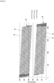
- FIG. 5 is a view illustrating a state in which ink is dropped onto the entire ink drop measurement pad according to the present invention.
- FIG. 6 is a view illustrating a measurement state of the ink dropped onto the ink drop measurement pad according to the present invention.
- a step s300 when an operation of spraying ink drops from the inkjet head toward the pad p and dropping the ink drops in the groove portions of the pad p is performed, the ink drops are dropped onto the pad p as illustrated in FIG. 5 .
- the ink drops are dropped in a form illustrated in FIG. 7 .
- the ink drops are dropped in a form illustrated in FIG. 8 .
- an ejection degree of the ink drop has an error depending on manufacturing and assembly tolerances in the ink head h and the ejection conditions, an error at a central position of the ink drop with ⁇ x and ⁇ y in the X-direction and the Y-direction occurs as many as an ejection error occurring at the groove portion 10 of the pad p.
- a step s410 of driving the Y2 stage 210 to transfer the pad p onto which the ink drops are dropped below an ink drop measurement device 230 is firstly performed.
- a step s420 of measuring a volume and position precision of each ink drop is performed by measuring a position (x, y) and a length 1 of each ink drop dropped in the step s300 as illustrated in FIG. 6 .
- a volume of the ink drop is automatically calculated because a width and a depth of the groove portion 10 are already known.
- a position deviation e( ⁇ x, ⁇ y) between a center (c) of each ink drop determined by the alignment mark 30 formed on the pad p and a position c1(x,y) of a substantially dropped ink drop is automatically calculated by the vision inspection device.
- An ink drop spread as long as possible in the groove 10 is more advantageous for measuring a length of the ink drop with higher precision.
- a small ink drop is spread at least 300 um to 400 um in the longitudinal direction of the groove portion by various variables considered in determining a size of the groove portion 10, i.e., by a shape of the groove portion 10, an interval and a depth of the pattern, and each surface state of the groove portion 10, a required measurement accuracy may be satisfied.
- the position deviation may be minimized to perform precise printing.
- a step s500 the pad p is moved below an ink removal device 250 installed on the X2 stage 240 by driving the Y2 stage 210 after measurement of all ink drops is finished.
- the ink removal device 250 including a vacuum suction device 251 capable of suctioning ink drops or a UV irradiation device 252 capable of curing ink drops according to the type of ink performs an operation of removing the ink of the pad p while moving along the X2 stage 240.
- the above-described features are all applied in the same manner even in the imprint device including the inkjet printer unit having the ink drop measurement pad, except that the ejected material may be changed to a functional material depending on products to which the object to be imprinted is applied.
- the present invention has an advantage that the volumes and positions of ink drops of each nozzle may be accurately measured to a precision of 0.5% or less simply and quickly.
- the present invention has an advantage of improving the position precision by performing printing that compensates for the above-described dropping error of each nozzle.
- the pad according to the present invention may be used in various cases as follows.
- Whether the ink drop exists may be measured to determine whether ink drops each having a sufficient size are ejected from all nozzles of the initial inkjet head after the inkjet printer is installed, and an insufficient air removal state or a nozzle clogging state of each nozzle may be identified and appropriately compensated by measuring the ink drop dropped onto the pad p.
- a volume ejected from the specific nozzle may be calculated by measuring the volume of ink drops dropped onto the pad p.
- one or a plurality of voltage waveforms in one nozzle for achieving target volumes of ink drops by ejecting a plurality of ink drops at the same position of the pad p may be set, and a desired voltage waveform may be selected and used.
- an ejected volume of each nozzle may be calculated by measuring a combined volume of the plurality of ink drops dropped onto the pad (p).
- a combination of a plurality of nozzles for achieving target volumes of ink drops by ejecting a plurality of ink drops at the same position of the pad p may be set, and/or a voltage waveform of each nozzle may be selected.
- the inkjet head continuously form four or seven different plurality of voltage waveforms to all nozzles and select one or a plurality of voltage waveforms among the different plurality of voltage waveforms to control the ink drops having sizes corresponding thereto to be ejected.
- the inkjet printer device may perform an operation of ejecting the predetermined ink drops from the predetermined nozzles according to pattern information required for each nozzle.
- sound waves generated when each nozzle ejects affect a surrounding of the nozzle when the nozzle ejects.
- effects of the crosstalk may be checked by analyzing the volume and position of the ink drops dropped through the ink drop measurement pad of the present invention, and the voltage waveform applied to the nozzle may be compensated to prevent the crosstalk.
- the present invention may be applied even to the field of display technology and micro-wire printing.
- the printing technology may be applied to the field of visible display applications, especially the field requiring RGB pixel printing.
- RGB Color Resist ink printing for manufacturing a color filter
- OLED display manufacturing that prints all layers such as HIL, HTL and EML by inkjet printing
- QDCC quantum dot color conversion
- perovskite color conversion ink printing OLED display manufacturing by merging blue deposition with red and green ink inkjet technology
- polymer OLED manufacturing that manufactures all of HIL, IL, and RGB EML by using inkjet ink
- QD ink printing for blue or UV ⁇ LED or MiniLED color conversion
- blue, red, and green ink printing of self-luminous QD displays self-luminous perovskite, and blue, red, and green ink printing.
- uniformity of the line width is important as the line width gradually decreases.
- the uniformity of the line width is required to be more uniformly maintained in a substrate for 5G communication (particularly, in 5G communication, since loss occurs intensively at a line edge, the uniformity of the line width in this aspect is important to reduce loss caused by straightness at the line edge).
- the technology of the present invention may be applied.
- the present invention has an advantage of being applied to the above-described fields and being used for measuring the size and position of the ink drop to secure the uniformity of 1% or less.
Landscapes
- Physics & Mathematics (AREA)
- General Physics & Mathematics (AREA)
- General Health & Medical Sciences (AREA)
- Health & Medical Sciences (AREA)
- Biochemistry (AREA)
- Life Sciences & Earth Sciences (AREA)
- Chemical & Material Sciences (AREA)
- Analytical Chemistry (AREA)
- Immunology (AREA)
- Pathology (AREA)
- Engineering & Computer Science (AREA)
- Textile Engineering (AREA)
- Toxicology (AREA)
- Quality & Reliability (AREA)
- Coating Apparatus (AREA)
Applications Claiming Priority (2)
| Application Number | Priority Date | Filing Date | Title |
|---|---|---|---|
| KR1020200188878A KR102509680B1 (ko) | 2020-12-31 | 2020-12-31 | 잉크방울 측정패드와 이를 구비한 잉크젯 프린터 장치 및 잉크방울 측정방법 |
| PCT/KR2021/011846 WO2022145621A1 (fr) | 2020-12-31 | 2021-09-02 | Tampon de mesure de gouttes d'encre, dispositif d'imprimante à jet d'encre le comprenant et procédé de mesure de gouttes d'encre |
Publications (2)
| Publication Number | Publication Date |
|---|---|
| EP4272964A1 true EP4272964A1 (fr) | 2023-11-08 |
| EP4272964A4 EP4272964A4 (fr) | 2024-11-13 |
Family
ID=82260880
Family Applications (1)
| Application Number | Title | Priority Date | Filing Date |
|---|---|---|---|
| EP21915419.2A Pending EP4272964A4 (fr) | 2020-12-31 | 2021-09-02 | Tampon de mesure de gouttes d'encre, dispositif d'imprimante à jet d'encre le comprenant et procédé de mesure de gouttes d'encre |
Country Status (5)
| Country | Link |
|---|---|
| US (1) | US20240042754A1 (fr) |
| EP (1) | EP4272964A4 (fr) |
| KR (1) | KR102509680B1 (fr) |
| CN (1) | CN116685471A (fr) |
| WO (1) | WO2022145621A1 (fr) |
Families Citing this family (2)
| Publication number | Priority date | Publication date | Assignee | Title |
|---|---|---|---|---|
| KR20240095743A (ko) | 2022-12-19 | 2024-06-26 | 세메스 주식회사 | 기판 처리 장치 |
| CN119688280A (zh) * | 2024-12-18 | 2025-03-25 | 季华实验室 | 喷墨特性测量方法、系统、设备及存储介质 |
Family Cites Families (15)
| Publication number | Priority date | Publication date | Assignee | Title |
|---|---|---|---|---|
| JP2001096776A (ja) * | 1999-09-28 | 2001-04-10 | Fuji Photo Film Co Ltd | 記録装置およびその方法、およびこの装置に用いられるためのクッションシート |
| JP2004177243A (ja) * | 2002-11-27 | 2004-06-24 | Dainippon Printing Co Ltd | 微量液滴の体積の測定方法およびそれに用いる微量液滴採取用基板 |
| JP4779569B2 (ja) | 2005-10-26 | 2011-09-28 | セイコーエプソン株式会社 | 薄膜形成方法及び薄膜形成装置 |
| JP2007125514A (ja) * | 2005-11-07 | 2007-05-24 | Seiko Epson Corp | 液滴吐出量測定方法、液滴吐出量測定用治具、液滴吐出量調整方法、液滴吐出量測定装置、描画装置、デバイス及び電気光学装置並びに電子機器 |
| KR20070070506A (ko) * | 2005-12-29 | 2007-07-04 | 엘지.필립스 엘시디 주식회사 | 잉크젯 인쇄 장비의 토출확인 시스템 및 방법, 및 상기시스템을 이용한 액정표시소자의 제조방법 |
| KR20070082386A (ko) * | 2006-02-16 | 2007-08-21 | 삼성전자주식회사 | 잉크젯 헤드의 노즐들로부터 토출되는 잉크 액적들의 양을균일하게 하기 위한 잉크 액적들의 정규화 방법 |
| KR100878763B1 (ko) * | 2007-05-09 | 2009-01-14 | 삼성전자주식회사 | 잉크 방울의 체적 측정 방법 및 이를 이용한 잉크젯 헤드의노즐 제어 방법 |
| JP4916022B2 (ja) * | 2007-09-26 | 2012-04-11 | 富士フイルム株式会社 | 画像形成方法及び装置 |
| JPWO2010005011A1 (ja) * | 2008-07-08 | 2012-01-05 | 株式会社アルバック | インクジェット式印刷装置、吐出量検査方法 |
| KR100997451B1 (ko) | 2008-10-02 | 2010-12-07 | (주)유니젯 | 잉크 드롭 체적 측정장치 및 방법 |
| KR101276328B1 (ko) * | 2010-11-12 | 2013-06-18 | 조성배 | 디지털 프린터의 피인쇄물 위치 결정방법 |
| JP6245726B2 (ja) * | 2013-01-23 | 2017-12-13 | 株式会社アルバック | インクジェット装置および液滴測定方法 |
| JP6329425B2 (ja) * | 2014-05-02 | 2018-05-23 | キヤノン株式会社 | インプリント装置、インプリント方法、および物品の製造方法 |
| KR102379011B1 (ko) * | 2014-12-31 | 2022-03-29 | 세메스 주식회사 | 기판 처리 장치, 토출량 측정 유닛, 그리고 기판 처리 방법 |
| CN110077112B (zh) * | 2018-04-18 | 2020-05-05 | 广东聚华印刷显示技术有限公司 | 打印喷嘴的墨滴偏移校正方法、装置和系统 |
-
2020
- 2020-12-31 KR KR1020200188878A patent/KR102509680B1/ko active Active
-
2021
- 2021-09-02 EP EP21915419.2A patent/EP4272964A4/fr active Pending
- 2021-09-02 US US18/267,187 patent/US20240042754A1/en active Pending
- 2021-09-02 WO PCT/KR2021/011846 patent/WO2022145621A1/fr not_active Ceased
- 2021-09-02 CN CN202180088504.1A patent/CN116685471A/zh active Pending
Also Published As
| Publication number | Publication date |
|---|---|
| WO2022145621A1 (fr) | 2022-07-07 |
| KR102509680B1 (ko) | 2023-03-15 |
| CN116685471A (zh) | 2023-09-01 |
| EP4272964A4 (fr) | 2024-11-13 |
| KR20220097738A (ko) | 2022-07-08 |
| US20240042754A1 (en) | 2024-02-08 |
Similar Documents
| Publication | Publication Date | Title |
|---|---|---|
| CN101484248B (zh) | 缺陷修复装置和缺陷修复方法 | |
| JP6472083B2 (ja) | インクジェット印刷装置及びインクジェットヘッド吐出性能評価方法 | |
| US9776425B2 (en) | Inkjet print device and inkjet head ejection performance evaluation method | |
| US20090102876A1 (en) | Droplet jet inspecting device, droplet jetting applicator and method for manufacturing coated body | |
| CN112829467B (zh) | 一种喷墨打印机用连续图文拼接方法 | |
| US20090309905A1 (en) | Droplet Discharging and Drawing Apparatus | |
| EP4272964A1 (fr) | Tampon de mesure de gouttes d'encre, dispositif d'imprimante à jet d'encre le comprenant et procédé de mesure de gouttes d'encre | |
| KR20080113108A (ko) | 액적 도포 장치 | |
| TWI484228B (zh) | Liquid material distribution method, manufacturing method of color filter, manufacturing method of organic EL display device | |
| CN118181947B (zh) | 一种喷印加工前的测试打印方法及喷墨打印系统 | |
| US20030206207A1 (en) | System and method for delivering droplets | |
| CN112829466A (zh) | 一种喷墨打印机用连续图文拼接方法 | |
| JP2002189115A (ja) | カラーフィルタ製造装置及びこれを用いた製造方法 | |
| US20030087026A1 (en) | Multi-nozzle printing method for PLED displays | |
| CN102267289B (zh) | 喷墨装置 | |
| CN101351276A (zh) | 液滴涂布装置 | |
| JP2006239570A (ja) | パターン形成装置、位置決め装置、位置決め方法、及び吐出部 | |
| CN116552143B (zh) | 一种十字龙门式打印调节装置及其检测调节方法 | |
| JP2007256312A (ja) | カラーフィルタの製造方法、有機エレクトロルミネッセンス素子の製造方法及びこれに用いるインクジェット塗工装置 | |
| JP4876598B2 (ja) | 印刷物の製造方法 | |
| US20250065619A1 (en) | Ink drop measurement pad, inkjet printer device having same, and method for measuring ink drop | |
| JP2009131789A (ja) | インキ吐出印刷装置 | |
| KR20090104661A (ko) | 도포장치 및 도포방법 | |
| JP7634706B2 (ja) | ディスプレイ製造用の基板上にプリントするための装置及び方法 | |
| JPH11258416A (ja) | カラーフィルタ製造装置および方法ならびにカラーフィルタ |
Legal Events
| Date | Code | Title | Description |
|---|---|---|---|
| STAA | Information on the status of an ep patent application or granted ep patent |
Free format text: STATUS: THE INTERNATIONAL PUBLICATION HAS BEEN MADE |
|
| PUAI | Public reference made under article 153(3) epc to a published international application that has entered the european phase |
Free format text: ORIGINAL CODE: 0009012 |
|
| STAA | Information on the status of an ep patent application or granted ep patent |
Free format text: STATUS: REQUEST FOR EXAMINATION WAS MADE |
|
| 17P | Request for examination filed |
Effective date: 20230630 |
|
| AK | Designated contracting states |
Kind code of ref document: A1 Designated state(s): AL AT BE BG CH CY CZ DE DK EE ES FI FR GB GR HR HU IE IS IT LI LT LU LV MC MK MT NL NO PL PT RO RS SE SI SK SM TR |
|
| DAV | Request for validation of the european patent (deleted) | ||
| DAX | Request for extension of the european patent (deleted) | ||
| A4 | Supplementary search report drawn up and despatched |
Effective date: 20241010 |
|
| RIC1 | Information provided on ipc code assigned before grant |
Ipc: G01N 21/89 20060101ALI20241004BHEP Ipc: G01N 21/88 20060101ALI20241004BHEP Ipc: G03F 9/00 20060101ALI20241004BHEP Ipc: B41J 2/165 20060101ALI20241004BHEP Ipc: B41J 2/045 20060101AFI20241004BHEP |