EP4273292A1 - Dispositif de système de dépôt sous vide et système de dépôt sous vide - Google Patents
Dispositif de système de dépôt sous vide et système de dépôt sous vide Download PDFInfo
- Publication number
- EP4273292A1 EP4273292A1 EP22171978.4A EP22171978A EP4273292A1 EP 4273292 A1 EP4273292 A1 EP 4273292A1 EP 22171978 A EP22171978 A EP 22171978A EP 4273292 A1 EP4273292 A1 EP 4273292A1
- Authority
- EP
- European Patent Office
- Prior art keywords
- coating
- shield
- coating window
- deposition
- main body
- Prior art date
- Legal status (The legal status is an assumption and is not a legal conclusion. Google has not performed a legal analysis and makes no representation as to the accuracy of the status listed.)
- Pending
Links
Images

Classifications
-
- C—CHEMISTRY; METALLURGY
- C23—COATING METALLIC MATERIAL; COATING MATERIAL WITH METALLIC MATERIAL; CHEMICAL SURFACE TREATMENT; DIFFUSION TREATMENT OF METALLIC MATERIAL; COATING BY VACUUM EVAPORATION, BY SPUTTERING, BY ION IMPLANTATION OR BY CHEMICAL VAPOUR DEPOSITION, IN GENERAL; INHIBITING CORROSION OF METALLIC MATERIAL OR INCRUSTATION IN GENERAL
- C23C—COATING METALLIC MATERIAL; COATING MATERIAL WITH METALLIC MATERIAL; SURFACE TREATMENT OF METALLIC MATERIAL BY DIFFUSION INTO THE SURFACE, BY CHEMICAL CONVERSION OR SUBSTITUTION; COATING BY VACUUM EVAPORATION, BY SPUTTERING, BY ION IMPLANTATION OR BY CHEMICAL VAPOUR DEPOSITION, IN GENERAL
- C23C14/00—Coating by vacuum evaporation, by sputtering or by ion implantation of the coating forming material
- C23C14/04—Coating on selected surface areas, e.g. using masks
- C23C14/042—Coating on selected surface areas, e.g. using masks using masks
-
- C—CHEMISTRY; METALLURGY
- C23—COATING METALLIC MATERIAL; COATING MATERIAL WITH METALLIC MATERIAL; CHEMICAL SURFACE TREATMENT; DIFFUSION TREATMENT OF METALLIC MATERIAL; COATING BY VACUUM EVAPORATION, BY SPUTTERING, BY ION IMPLANTATION OR BY CHEMICAL VAPOUR DEPOSITION, IN GENERAL; INHIBITING CORROSION OF METALLIC MATERIAL OR INCRUSTATION IN GENERAL
- C23C—COATING METALLIC MATERIAL; COATING MATERIAL WITH METALLIC MATERIAL; SURFACE TREATMENT OF METALLIC MATERIAL BY DIFFUSION INTO THE SURFACE, BY CHEMICAL CONVERSION OR SUBSTITUTION; COATING BY VACUUM EVAPORATION, BY SPUTTERING, BY ION IMPLANTATION OR BY CHEMICAL VAPOUR DEPOSITION, IN GENERAL
- C23C14/00—Coating by vacuum evaporation, by sputtering or by ion implantation of the coating forming material
- C23C14/22—Coating by vacuum evaporation, by sputtering or by ion implantation of the coating forming material characterised by the process of coating
- C23C14/54—Controlling or regulating the coating process
- C23C14/541—Heating or cooling of the substrates
-
- C—CHEMISTRY; METALLURGY
- C23—COATING METALLIC MATERIAL; COATING MATERIAL WITH METALLIC MATERIAL; CHEMICAL SURFACE TREATMENT; DIFFUSION TREATMENT OF METALLIC MATERIAL; COATING BY VACUUM EVAPORATION, BY SPUTTERING, BY ION IMPLANTATION OR BY CHEMICAL VAPOUR DEPOSITION, IN GENERAL; INHIBITING CORROSION OF METALLIC MATERIAL OR INCRUSTATION IN GENERAL
- C23C—COATING METALLIC MATERIAL; COATING MATERIAL WITH METALLIC MATERIAL; SURFACE TREATMENT OF METALLIC MATERIAL BY DIFFUSION INTO THE SURFACE, BY CHEMICAL CONVERSION OR SUBSTITUTION; COATING BY VACUUM EVAPORATION, BY SPUTTERING, BY ION IMPLANTATION OR BY CHEMICAL VAPOUR DEPOSITION, IN GENERAL
- C23C14/00—Coating by vacuum evaporation, by sputtering or by ion implantation of the coating forming material
- C23C14/22—Coating by vacuum evaporation, by sputtering or by ion implantation of the coating forming material characterised by the process of coating
- C23C14/56—Apparatus specially adapted for continuous coating; Arrangements for maintaining the vacuum, e.g. vacuum locks
-
- C—CHEMISTRY; METALLURGY
- C23—COATING METALLIC MATERIAL; COATING MATERIAL WITH METALLIC MATERIAL; CHEMICAL SURFACE TREATMENT; DIFFUSION TREATMENT OF METALLIC MATERIAL; COATING BY VACUUM EVAPORATION, BY SPUTTERING, BY ION IMPLANTATION OR BY CHEMICAL VAPOUR DEPOSITION, IN GENERAL; INHIBITING CORROSION OF METALLIC MATERIAL OR INCRUSTATION IN GENERAL
- C23C—COATING METALLIC MATERIAL; COATING MATERIAL WITH METALLIC MATERIAL; SURFACE TREATMENT OF METALLIC MATERIAL BY DIFFUSION INTO THE SURFACE, BY CHEMICAL CONVERSION OR SUBSTITUTION; COATING BY VACUUM EVAPORATION, BY SPUTTERING, BY ION IMPLANTATION OR BY CHEMICAL VAPOUR DEPOSITION, IN GENERAL
- C23C14/00—Coating by vacuum evaporation, by sputtering or by ion implantation of the coating forming material
- C23C14/22—Coating by vacuum evaporation, by sputtering or by ion implantation of the coating forming material characterised by the process of coating
- C23C14/56—Apparatus specially adapted for continuous coating; Arrangements for maintaining the vacuum, e.g. vacuum locks
- C23C14/562—Apparatus specially adapted for continuous coating; Arrangements for maintaining the vacuum, e.g. vacuum locks for coating elongated substrates
-
- H—ELECTRICITY
- H01—ELECTRIC ELEMENTS
- H01J—ELECTRIC DISCHARGE TUBES OR DISCHARGE LAMPS
- H01J37/00—Discharge tubes with provision for introducing objects or material to be exposed to the discharge, e.g. for the purpose of examination or processing thereof
- H01J37/32—Gas-filled discharge tubes
- H01J37/34—Gas-filled discharge tubes operating with cathodic sputtering
-
- H—ELECTRICITY
- H01—ELECTRIC ELEMENTS
- H01J—ELECTRIC DISCHARGE TUBES OR DISCHARGE LAMPS
- H01J37/00—Discharge tubes with provision for introducing objects or material to be exposed to the discharge, e.g. for the purpose of examination or processing thereof
- H01J37/32—Gas-filled discharge tubes
- H01J37/34—Gas-filled discharge tubes operating with cathodic sputtering
- H01J37/3411—Constructional aspects of the reactor
- H01J37/3414—Targets
- H01J37/3417—Arrangements
-
- H—ELECTRICITY
- H01—ELECTRIC ELEMENTS
- H01J—ELECTRIC DISCHARGE TUBES OR DISCHARGE LAMPS
- H01J37/00—Discharge tubes with provision for introducing objects or material to be exposed to the discharge, e.g. for the purpose of examination or processing thereof
- H01J37/32—Gas-filled discharge tubes
- H01J37/34—Gas-filled discharge tubes operating with cathodic sputtering
- H01J37/3411—Constructional aspects of the reactor
- H01J37/3447—Collimators, shutters, apertures
-
- H—ELECTRICITY
- H01—ELECTRIC ELEMENTS
- H01J—ELECTRIC DISCHARGE TUBES OR DISCHARGE LAMPS
- H01J37/00—Discharge tubes with provision for introducing objects or material to be exposed to the discharge, e.g. for the purpose of examination or processing thereof
- H01J37/32—Gas-filled discharge tubes
- H01J37/34—Gas-filled discharge tubes operating with cathodic sputtering
- H01J37/3488—Constructional details of particle beam apparatus not otherwise provided for, e.g. arrangement, mounting, housing, environment; special provisions for cleaning or maintenance of the apparatus
- H01J37/3497—Temperature of target
Definitions
- the present disclosure generally relates to devices for vacuum deposition systems and systems for vacuum deposition.
- PVD Physical Vapor Deposition
- CVD Chemical Vapor Deposition
- the chambers are usually provided with plates/parts that can be easily changed for cleaning.
- coating windows used as masking limits the coating on the substrate.
- the edge of the coating window is heavily coated during the deposition process. As a consequence, the coating window becomes hot.
- the substrate is made of a temperature-sensitive film. The maximum temperature tolerance of the film and the temperature of the coating window limit the maximum coating rate.
- the substrate is cooled by a chill roll during coating.
- the coating window is suitably connected to the chill roll to ensure a sufficient cooling. This leads to difficult and costly assembly conditions.
- the coating window can only be removed from the system with great effort.
- the chill roll and shield are moved against each other and cooling remains restricted. Since regular cleaning of the coating the coating window is indispensable, this has a negative effect on the productivity of the system.
- the systems comprise a chamber with a cooled coating roller that moves the substrate along in front of the PVD sources.
- the coating sources are on a trolley to move the sources out of the vacuum chamber (deposition chamber) for maintenance.
- the coating trolley closes the vacuum chamber.
- On the trolley are the magnetron cathodes/coating sources with shields for receiving the recoating (backcoating), other components and a cooling system underneath the vacuum chamber.
- the shields are attached to the cooling system.
- the coating windows are mounted in the vacuum chamber for better cooling. Installation and removal is time-consuming.
- One object of the invention is to provide coating windows that are easy to change and that remain sufficiently cold to achieve high deposition rates. The object is achieved with the features of the independent claims. Dependent claims define preferred embodiments of the invention.
- the present disclosure provides a device for vacuum deposition systems, comprising: a movable main body, at least one deposition source mounted on the movable main body, at least one coating window associated with the at least one deposition source and mounted on the movable main body, and at least one cooling device connected to the at least one coating window and mounted on the movable main body.
- the movable main body is movable relative to a vacuum chamber of a vacuum deposition system such that the movable main body can be inserted into and withdrawn from the vacuum chamber.
- the movable main body closes the vacuum chamber when completely inserted therein.
- the at least one coating window comprises a housing with an opening.
- the opening is located at a side of the coating window that (in use) faces a substrate to be coated.
- the housing comprises sidewalls extending substantially in a deposition direction.
- the hosuing comprises frontwalls extending substantially perpendicular to the deposition direction.
- the frontwalls comprises the opening therein.
- the at least one depositon source is configured to deposit material within a deposition space with a main deposition direction aligned towards the opening of the at least one coating window.
- the housing of the at least one coating window is configured to surround the at least one deposition source within the deposition space such that material that is not deposited through the opening is deposited on an inner side of the housing.
- each of the at least one coating window is associated with a respective one of the at least one deposition source.
- the device further comprises at least one shield located between the at least one deposition source and the at least one coating window, wherein the at least one shield and the at least one coating window are connected to the at least one cooling device.
- a shield is carefull designed to receive most of the unused coating material, i.e. backcoating that is the coating material that is not deposited on the substrate. This reduces the heat of the coating window and helps to overcome limitations in coating speed of the prior art.
- the at least one shield and the at least one coating window are connected to separate cooling devices or more preferably to one and the same cooling device.
- the at least one shield is configured to shield a majority of the at least one coating window.
- the at least one shield comprises a shield housing with a shield opening, wherein the shield opening is aligned with the opening of the at least one coating window.
- the shield housing is located between the at least one deposition source and the at least one coating window with a predetermined spacing with respect to the coating window.
- the shield opening is larger by a predetermined amount than the opening of the at least one coating window.
- the shield has substantially the same shape as the coating window.
- the at least one cooling device is connected to the at least one shield.
- the present disclosure also provides a system for vacuum deposition, comprising: a vacuum chamber, a substrate carrier located within the vacuum chamber and having a vacuum chamber cooling device configured to cool the subtsrate carrier, and a device for vacuum deposition systems as described above.
- the movable main body is movable relative to the vacuum chamber such that the movable main body can be inserted into and withdrawn from the vacuum chamber.
- the substrate carrier is configured to hold a substrate, and wherein the substrate carrier is aligned with the at least one coating window such that material can be deposited onto the subtsrate through the at least one coating window.
- the vacuum chamber cooling device and the at least one cooling device are separate devices.
- the shield is mounted on the cathode trolley for ease of maintenance.
- a connection to the cooling system is preferably ensured. Due to the long distance to the heat sink, the cooling efficiency is limited.
- the present disclosure also provides a device for vacuum deposition systems, comprising: at least one deposition source, at least one coating window associated with the at least one deposition source, at least one cooling device connected to the at least one coating window, and at least one shield located between the at least one deposition source and the at least one coating window, wherein the at least one shield and the at least one coating window are connected to the at least one cooling device.
- a shield is carefull designed to receive most of the unused coating material, i.e. backcoating that is the coating material that is not deposited on the substrate. This reduces the heat of the coating window and helps to overcome limitations in coating speed of the prior art.
- shields are preferably formed so that most of the backcoating is received by them instead of the coating windows. Thus, the amount of backcoating on the coating windows is reduced.
- the shields are preferably positioned so that thermal deformation does not affect the coating process.
- the shields are configured such that high temperatures of the shields do not lead to heating of the substrate.
- Shields and coating windows and their cooling are preferably optimized to minimize substrate heating.
- the shields, and not the coating window may become hot and deform.
- the present disclosure is not limited to the exemplary embodiments and applications described and illustrated herein. Additionally, the specific order and/or hierarchy of steps in the methods disclosed herein are merely exemplary approaches. Based upon design preferences, the specific order or hierarchy of steps of the disclosed methods or processes can be re-arranged while remaining within the scope of the present disclosure. Thus, those of ordinary skill in the art will understand that the methods and techniques disclosed herein present various steps or acts in a sample order, and the present disclosure is not limited to the specific order or hierarchy presented unless expressly stated otherwise.
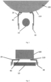
- Fig. 1 is a sectional drawing along the coating direction.
- Fig. 1 shows the cooled coating roller 100 that moves the substrate 110 along the coating window 20.
- Fig. 1 further shows the deposition source 10 and a cooling device 30.
- Fig. 2 is a respective sectional drawing transverse to the coating direction in correspondence with the embodiment shown in Fig. 1 .
- the same reference numerals indicate the same elements and will not be repeated.
- the coating window 20 accommodates the entire backcoating 40.
- the deposition source 10 the coating window 20 and the cooling device 30 are installed on a movable main body.
- the movable main body is movable with respect to the vacuum chamber (not shown), which comprises the cooled coating roller 100 (also referred to as a substrate carrier).
- the movable main body opens and closes the deposition chamber (also referred to as the vacuum chamber).
- the backcoating 40 is the coating that does not reach the substrate, but rather the coating that is deposited on the coating window20.
- the shape of the coating window 20 is preferably configured to receive all or at least a significant amount of the backcoating 40.
- the cooled coating roller may be colled by a vacuum chamber cooling device (not shown), which may be different from the cooling device 30 and may be located in the vacuum chamber.
- the coating window 20 comprises an opening towards the substrate 110 to deposit material therethrough.
- the coating window 20 comprises sidewalls that are directed substantially in a deposition direction and frontwalls substantially perpendicular to the deposition direction (parallel to the substrate), wherein the frontwalls comprise said opening.
- a first end of the coating window 20 is connected to a cooling device 30.
- the frontwalls are positioned on a second end of the coating window 20 opposite the first end.
- Fig. 3 is a sectional drawing along the coating direction.
- Fig. 3 shows the cooled coating roller 100 that moves the substrate 110 along the coating window 20.
- Fig. 3 further shows the deposition source 10, a cooling device 30 and a shield 50.
- Fig. 4 is a respective sectional drawing transverse to the coating direction in correspondence with the embodiment shown in Fig. 3 .
- the same reference numerals indicate the same elements and will not be repeated.
- the embodiment of Figs. 3 and 4 is largely identical to the embodiment of Figs. 1 and 2 (besides the use of an additional shield) and thus the respeticve description thereof is not repeated.
- the shield 50 accommodates the majority of the backcoating 40, whereas the coating window 20 only accommodates minor parts of the backcoating 40.
- the shield 50 may become hot and can deform without negatively affecting the process, whereas the coating window 20 is heated up less (compared to, e.g., the embodiment of Fig. 1 ).
- the shield 50 is located on the inside of the coating window 20 and preferably has a predetermined distance to the coating window 20. As described above, the shield 50 is configured such that a majority of the backcoating 40 is deposited on the shield 50 and only a small amount of backcoating 40 is deposited on the coating window 20, in particular around the opening of the coating window 20.
- the shield 50 comprises sidewalls that substantially follow the sidewalls of the coating window 20.
- the shield 50 is located close to the opening of the coating window 20, preferably with a predetermined distance from the opening of the coating window 20.
- the predetermined distance is preferably chosen as small as possible and such that the shield 50 does not negatively influence the coating process.
- the predetermined distance may vary over the extend of the shield 50.
- the shield 50 comprises an opening in its frontwalls, which may be slightly larger than the opening provided in the coating window 20. There may be a gap between the opening of the shield 50 and the opening of the coating window 20. It is this gap that receives some (small) amount of backcoating 40, which thus may reach the coating window 20 as described above.
- the coating window 20 may be provided with soldered-on heat sinks in the substrate area. This may allow a larger amount of coating.
- the use of a cooling device 30 that directly cools the coating window 20 (that is located on a movable main body) and/or the use of a shield 50 allows a one-piece coating window 20, which can be changed with little effort.
- the coating window 20 remains colder in the process. This allows to run at higher outputs or higher coating rates. Thus, the product quality is improved and productivity is increased.
- any reference to an element herein using a designation such as "first,” “second,” and so forth does not generally limit the quantity or order of those elements. Rather, these designations can be used herein as a convenient means of distinguishing between two or more elements or instances of an element. Thus, a reference to first and second elements does not mean that only two elements can be employed, or that the first element must precede the second element in some manner.
Landscapes
- Chemical & Material Sciences (AREA)
- Engineering & Computer Science (AREA)
- Chemical Kinetics & Catalysis (AREA)
- Materials Engineering (AREA)
- Mechanical Engineering (AREA)
- Metallurgy (AREA)
- Organic Chemistry (AREA)
- Physics & Mathematics (AREA)
- Plasma & Fusion (AREA)
- Analytical Chemistry (AREA)
- Physical Vapour Deposition (AREA)
Priority Applications (6)
| Application Number | Priority Date | Filing Date | Title |
|---|---|---|---|
| EP22171978.4A EP4273292A1 (fr) | 2022-05-06 | 2022-05-06 | Dispositif de système de dépôt sous vide et système de dépôt sous vide |
| JP2024564638A JP2025515382A (ja) | 2022-05-06 | 2023-05-05 | 真空蒸着システムのためのデバイス及び真空蒸着のためのシステム |
| CN202380036224.5A CN119096001A (zh) | 2022-05-06 | 2023-05-05 | 用于真空沉积系统的装置以及用于真空沉积的系统 |
| PCT/EP2023/061923 WO2023214005A1 (fr) | 2022-05-06 | 2023-05-05 | Dispositif pour système de dépôt sous vide et système de dépôt sous vide |
| US18/862,383 US20250290197A1 (en) | 2022-05-06 | 2023-05-05 | Device for vacuum deposition system and system for vacuum deposition |
| KR1020247039422A KR20250004338A (ko) | 2022-05-06 | 2023-05-05 | 진공 증착 시스템을 위한 디바이스 및 진공 증착을 위한 시스템 |
Applications Claiming Priority (1)
| Application Number | Priority Date | Filing Date | Title |
|---|---|---|---|
| EP22171978.4A EP4273292A1 (fr) | 2022-05-06 | 2022-05-06 | Dispositif de système de dépôt sous vide et système de dépôt sous vide |
Publications (1)
| Publication Number | Publication Date |
|---|---|
| EP4273292A1 true EP4273292A1 (fr) | 2023-11-08 |
Family
ID=81585627
Family Applications (1)
| Application Number | Title | Priority Date | Filing Date |
|---|---|---|---|
| EP22171978.4A Pending EP4273292A1 (fr) | 2022-05-06 | 2022-05-06 | Dispositif de système de dépôt sous vide et système de dépôt sous vide |
Country Status (6)
| Country | Link |
|---|---|
| US (1) | US20250290197A1 (fr) |
| EP (1) | EP4273292A1 (fr) |
| JP (1) | JP2025515382A (fr) |
| KR (1) | KR20250004338A (fr) |
| CN (1) | CN119096001A (fr) |
| WO (1) | WO2023214005A1 (fr) |
Families Citing this family (1)
| Publication number | Priority date | Publication date | Assignee | Title |
|---|---|---|---|---|
| TWI885636B (zh) * | 2022-12-12 | 2025-06-01 | 美商因特瓦克公司 | 具有穩定接地陽極開口的薄膜處理腔室 |
Citations (5)
| Publication number | Priority date | Publication date | Assignee | Title |
|---|---|---|---|---|
| US20010008208A1 (en) * | 1998-02-17 | 2001-07-19 | Masayasu Futagawa | Sputtering apparatus capable of changing distance between substrate and deposition preventing plate used for film formation |
| DE202013103010U1 (de) * | 2013-07-08 | 2013-09-10 | Von Ardenne Anlagentechnik Gmbh | Begrenzung für den Plasmaraum eines Magnetrons |
| US20140147593A1 (en) * | 2012-11-27 | 2014-05-29 | Intermolecular, Inc. | Liquid Cooled Sputter Apertured Shields |
| US20210381102A1 (en) * | 2020-06-04 | 2021-12-09 | Applied Materials, Inc. | Temperature-controlled shield, material deposition apparatus and method for depositing a material onto a substrate |
| US20210381095A1 (en) * | 2020-06-04 | 2021-12-09 | Applied Materials, Inc. | Vapor deposition apparatus and method for coating a substrate in a vacuum chamber |
Family Cites Families (1)
| Publication number | Priority date | Publication date | Assignee | Title |
|---|---|---|---|---|
| JPH1060628A (ja) * | 1996-08-16 | 1998-03-03 | Sony Corp | 材料飛翔装置及び材料飛翔源 |
-
2022
- 2022-05-06 EP EP22171978.4A patent/EP4273292A1/fr active Pending
-
2023
- 2023-05-05 US US18/862,383 patent/US20250290197A1/en active Pending
- 2023-05-05 WO PCT/EP2023/061923 patent/WO2023214005A1/fr not_active Ceased
- 2023-05-05 KR KR1020247039422A patent/KR20250004338A/ko active Pending
- 2023-05-05 CN CN202380036224.5A patent/CN119096001A/zh active Pending
- 2023-05-05 JP JP2024564638A patent/JP2025515382A/ja active Pending
Patent Citations (5)
| Publication number | Priority date | Publication date | Assignee | Title |
|---|---|---|---|---|
| US20010008208A1 (en) * | 1998-02-17 | 2001-07-19 | Masayasu Futagawa | Sputtering apparatus capable of changing distance between substrate and deposition preventing plate used for film formation |
| US20140147593A1 (en) * | 2012-11-27 | 2014-05-29 | Intermolecular, Inc. | Liquid Cooled Sputter Apertured Shields |
| DE202013103010U1 (de) * | 2013-07-08 | 2013-09-10 | Von Ardenne Anlagentechnik Gmbh | Begrenzung für den Plasmaraum eines Magnetrons |
| US20210381102A1 (en) * | 2020-06-04 | 2021-12-09 | Applied Materials, Inc. | Temperature-controlled shield, material deposition apparatus and method for depositing a material onto a substrate |
| US20210381095A1 (en) * | 2020-06-04 | 2021-12-09 | Applied Materials, Inc. | Vapor deposition apparatus and method for coating a substrate in a vacuum chamber |
Also Published As
| Publication number | Publication date |
|---|---|
| US20250290197A1 (en) | 2025-09-18 |
| KR20250004338A (ko) | 2025-01-07 |
| JP2025515382A (ja) | 2025-05-14 |
| WO2023214005A1 (fr) | 2023-11-09 |
| CN119096001A (zh) | 2024-12-06 |
Similar Documents
| Publication | Publication Date | Title |
|---|---|---|
| EP0562035B1 (fr) | Procedes reduisant au minimum la production de particules dans des reacteurs de depot chimique en phase vapeur | |
| EP0619381A1 (fr) | Chambre de déposition en phase vapeur | |
| US20250290197A1 (en) | Device for vacuum deposition system and system for vacuum deposition | |
| CN107406974B (zh) | 用于执行真空辅助的涂层方法的涂层腔,隔热板以及涂层方法 | |
| WO1998053484A1 (fr) | Appareil de traitement | |
| TWI802617B (zh) | 基板處理設備以及處理基板及製造經處理工件的方法 | |
| US11834743B2 (en) | Segmented showerhead for uniform delivery of multiple precursors | |
| CN104995727A (zh) | 带有温度调节布置的加工布置和加工基底的方法 | |
| US11637000B2 (en) | Coating device for conducting high efficient low temperature coating | |
| WO2020033757A1 (fr) | Pomme de douche pour fournir de multiples matériaux à une chambre de traitement | |
| US11549173B2 (en) | Sputtering apparatus | |
| US5240580A (en) | Conmag shield | |
| US20170175254A1 (en) | Substrate carrier that carries a substrate on each of two broad sides of the substrate carrier that face away from each other | |
| CN111503430B (zh) | 半导体工艺腔室 | |
| US20050160979A1 (en) | Method and apparatus for applying a polycrystalline film to a substrate | |
| EP3118349B1 (fr) | Source de dépôt, appareil de dépôt et son procédé de fonctionnement | |
| CN114381693A (zh) | 真空蒸镀装置用的蒸镀源 | |
| JPH0665726A (ja) | スパッタ装置 | |
| JP2008121053A (ja) | スパッタリング成膜装置及び成膜方法 | |
| TW202209400A (zh) | 具有改進的選擇性和流導性的金屬氧化物預清潔腔室 | |
| US20140245949A1 (en) | Film forming device for solar cell |
Legal Events
| Date | Code | Title | Description |
|---|---|---|---|
| PUAI | Public reference made under article 153(3) epc to a published international application that has entered the european phase |
Free format text: ORIGINAL CODE: 0009012 |
|
| STAA | Information on the status of an ep patent application or granted ep patent |
Free format text: STATUS: THE APPLICATION HAS BEEN PUBLISHED |
|
| AK | Designated contracting states |
Kind code of ref document: A1 Designated state(s): AL AT BE BG CH CY CZ DE DK EE ES FI FR GB GR HR HU IE IS IT LI LT LU LV MC MK MT NL NO PL PT RO RS SE SI SK SM TR |
|
| STAA | Information on the status of an ep patent application or granted ep patent |
Free format text: STATUS: REQUEST FOR EXAMINATION WAS MADE |
|
| 17P | Request for examination filed |
Effective date: 20240404 |
|
| RBV | Designated contracting states (corrected) |
Designated state(s): AL AT BE BG CH CY CZ DE DK EE ES FI FR GB GR HR HU IE IS IT LI LT LU LV MC MK MT NL NO PL PT RO RS SE SI SK SM TR |
|
| P01 | Opt-out of the competence of the unified patent court (upc) registered |
Free format text: CASE NUMBER: APP_9401/2025 Effective date: 20250225 |