EP4273360A1 - Charnière pivotante et vantail de porte pivotant - Google Patents
Charnière pivotante et vantail de porte pivotant Download PDFInfo
- Publication number
- EP4273360A1 EP4273360A1 EP22171124.5A EP22171124A EP4273360A1 EP 4273360 A1 EP4273360 A1 EP 4273360A1 EP 22171124 A EP22171124 A EP 22171124A EP 4273360 A1 EP4273360 A1 EP 4273360A1
- Authority
- EP
- European Patent Office
- Prior art keywords
- door leaf
- cam
- pivot hinge
- pivot
- end part
- Prior art date
- Legal status (The legal status is an assumption and is not a legal conclusion. Google has not performed a legal analysis and makes no representation as to the accuracy of the status listed.)
- Granted
Links
Images


Classifications
-
- E—FIXED CONSTRUCTIONS
- E05—LOCKS; KEYS; WINDOW OR DOOR FITTINGS; SAFES
- E05D—HINGES OR SUSPENSION DEVICES FOR DOORS, WINDOWS OR WINGS
- E05D11/00—Additional features or accessories of hinges
- E05D11/10—Devices for preventing movement between relatively-movable hinge parts
- E05D11/1028—Devices for preventing movement between relatively-movable hinge parts for maintaining the hinge in two or more positions, e.g. intermediate or fully open
- E05D11/105—Devices for preventing movement between relatively-movable hinge parts for maintaining the hinge in two or more positions, e.g. intermediate or fully open the maintaining means acting perpendicularly to the pivot axis
- E05D11/1064—Devices for preventing movement between relatively-movable hinge parts for maintaining the hinge in two or more positions, e.g. intermediate or fully open the maintaining means acting perpendicularly to the pivot axis with a coil spring perpendicular to the pivot axis
-
- E—FIXED CONSTRUCTIONS
- E05—LOCKS; KEYS; WINDOW OR DOOR FITTINGS; SAFES
- E05D—HINGES OR SUSPENSION DEVICES FOR DOORS, WINDOWS OR WINGS
- E05D15/00—Suspension arrangements for wings
- E05D15/48—Suspension arrangements for wings allowing alternative movements
- E05D15/54—Suspension arrangements for wings allowing alternative movements for opening both inwards and outwards
-
- E—FIXED CONSTRUCTIONS
- E05—LOCKS; KEYS; WINDOW OR DOOR FITTINGS; SAFES
- E05D—HINGES OR SUSPENSION DEVICES FOR DOORS, WINDOWS OR WINGS
- E05D7/00—Hinges or pivots of special construction
- E05D7/08—Hinges or pivots of special construction for use in suspensions comprising two spigots placed at opposite edges of the wing, especially at the top and the bottom, e.g. trunnions
- E05D7/081—Hinges or pivots of special construction for use in suspensions comprising two spigots placed at opposite edges of the wing, especially at the top and the bottom, e.g. trunnions the pivot axis of the wing being situated near one edge of the wing, especially at the top and bottom, e.g. trunnions
-
- E—FIXED CONSTRUCTIONS
- E05—LOCKS; KEYS; WINDOW OR DOOR FITTINGS; SAFES
- E05D—HINGES OR SUSPENSION DEVICES FOR DOORS, WINDOWS OR WINGS
- E05D11/00—Additional features or accessories of hinges
- E05D11/10—Devices for preventing movement between relatively-movable hinge parts
- E05D11/1028—Devices for preventing movement between relatively-movable hinge parts for maintaining the hinge in two or more positions, e.g. intermediate or fully open
- E05D2011/1035—Devices for preventing movement between relatively-movable hinge parts for maintaining the hinge in two or more positions, e.g. intermediate or fully open with circumferential and evenly distributed detents around the pivot-axis
-
- E—FIXED CONSTRUCTIONS
- E05—LOCKS; KEYS; WINDOW OR DOOR FITTINGS; SAFES
- E05F—DEVICES FOR MOVING WINGS INTO OPEN OR CLOSED POSITION; CHECKS FOR WINGS; WING FITTINGS NOT OTHERWISE PROVIDED FOR, CONCERNED WITH THE FUNCTIONING OF THE WING
- E05F1/00—Closers or openers for wings, not otherwise provided for in this subclass
- E05F1/08—Closers or openers for wings, not otherwise provided for in this subclass spring-actuated, e.g. for horizontally sliding wings
- E05F1/10—Closers or openers for wings, not otherwise provided for in this subclass spring-actuated, e.g. for horizontally sliding wings for swinging wings, e.g. counterbalance
- E05F1/12—Mechanisms in the shape of hinges or pivots, operated by springs
- E05F1/1246—Mechanisms in the shape of hinges or pivots, operated by springs with a coil spring perpendicular to the pivot axis
- E05F1/1253—Mechanisms in the shape of hinges or pivots, operated by springs with a coil spring perpendicular to the pivot axis with a compression spring
-
- E—FIXED CONSTRUCTIONS
- E05—LOCKS; KEYS; WINDOW OR DOOR FITTINGS; SAFES
- E05Y—INDEXING SCHEME ASSOCIATED WITH SUBCLASSES E05D AND E05F, RELATING TO CONSTRUCTION ELEMENTS, ELECTRIC CONTROL, POWER SUPPLY, POWER SIGNAL OR TRANSMISSION, USER INTERFACES, MOUNTING OR COUPLING, DETAILS, ACCESSORIES, AUXILIARY OPERATIONS NOT OTHERWISE PROVIDED FOR, APPLICATION THEREOF
- E05Y2201/00—Constructional elements; Accessories therefor
- E05Y2201/10—Covers; Housings
-
- E—FIXED CONSTRUCTIONS
- E05—LOCKS; KEYS; WINDOW OR DOOR FITTINGS; SAFES
- E05Y—INDEXING SCHEME ASSOCIATED WITH SUBCLASSES E05D AND E05F, RELATING TO CONSTRUCTION ELEMENTS, ELECTRIC CONTROL, POWER SUPPLY, POWER SIGNAL OR TRANSMISSION, USER INTERFACES, MOUNTING OR COUPLING, DETAILS, ACCESSORIES, AUXILIARY OPERATIONS NOT OTHERWISE PROVIDED FOR, APPLICATION THEREOF
- E05Y2201/00—Constructional elements; Accessories therefor
- E05Y2201/60—Suspension or transmission members; Accessories therefor
- E05Y2201/622—Suspension or transmission members elements
- E05Y2201/638—Cams; Ramps
-
- E—FIXED CONSTRUCTIONS
- E05—LOCKS; KEYS; WINDOW OR DOOR FITTINGS; SAFES
- E05Y—INDEXING SCHEME ASSOCIATED WITH SUBCLASSES E05D AND E05F, RELATING TO CONSTRUCTION ELEMENTS, ELECTRIC CONTROL, POWER SUPPLY, POWER SIGNAL OR TRANSMISSION, USER INTERFACES, MOUNTING OR COUPLING, DETAILS, ACCESSORIES, AUXILIARY OPERATIONS NOT OTHERWISE PROVIDED FOR, APPLICATION THEREOF
- E05Y2600/00—Mounting or coupling arrangements for elements provided for in this subclass
- E05Y2600/40—Mounting location; Visibility of the elements
- E05Y2600/46—Mounting location; Visibility of the elements in or on the wing
-
- E—FIXED CONSTRUCTIONS
- E05—LOCKS; KEYS; WINDOW OR DOOR FITTINGS; SAFES
- E05Y—INDEXING SCHEME ASSOCIATED WITH SUBCLASSES E05D AND E05F, RELATING TO CONSTRUCTION ELEMENTS, ELECTRIC CONTROL, POWER SUPPLY, POWER SIGNAL OR TRANSMISSION, USER INTERFACES, MOUNTING OR COUPLING, DETAILS, ACCESSORIES, AUXILIARY OPERATIONS NOT OTHERWISE PROVIDED FOR, APPLICATION THEREOF
- E05Y2800/00—Details, accessories and auxiliary operations not otherwise provided for
- E05Y2800/20—Combinations of elements
- E05Y2800/21—Combinations of elements of identical elements, e.g. of identical compression springs
-
- E—FIXED CONSTRUCTIONS
- E05—LOCKS; KEYS; WINDOW OR DOOR FITTINGS; SAFES
- E05Y—INDEXING SCHEME ASSOCIATED WITH SUBCLASSES E05D AND E05F, RELATING TO CONSTRUCTION ELEMENTS, ELECTRIC CONTROL, POWER SUPPLY, POWER SIGNAL OR TRANSMISSION, USER INTERFACES, MOUNTING OR COUPLING, DETAILS, ACCESSORIES, AUXILIARY OPERATIONS NOT OTHERWISE PROVIDED FOR, APPLICATION THEREOF
- E05Y2800/00—Details, accessories and auxiliary operations not otherwise provided for
- E05Y2800/26—Form or shape
-
- E—FIXED CONSTRUCTIONS
- E05—LOCKS; KEYS; WINDOW OR DOOR FITTINGS; SAFES
- E05Y—INDEXING SCHEME ASSOCIATED WITH SUBCLASSES E05D AND E05F, RELATING TO CONSTRUCTION ELEMENTS, ELECTRIC CONTROL, POWER SUPPLY, POWER SIGNAL OR TRANSMISSION, USER INTERFACES, MOUNTING OR COUPLING, DETAILS, ACCESSORIES, AUXILIARY OPERATIONS NOT OTHERWISE PROVIDED FOR, APPLICATION THEREOF
- E05Y2900/00—Application of doors, windows, wings or fittings thereof
- E05Y2900/10—Application of doors, windows, wings or fittings thereof for buildings or parts thereof
- E05Y2900/13—Type of wing
- E05Y2900/132—Doors
Definitions
- the invention relates to the field of pivot hinges having a pivot pin member for pivotally connecting a pivotal door leaf with a structural element, e.g. a floor or a ceiling of a building or a door frame mounted in or on a floor or ceiling of a building, the door leaf having an upper edge, lower edge, an inner side edge and an outer side edge, and the pivot pin member defining a vertical pivot axis for the door leaf, wherein the pivot pin member has a cam, the pivot hinge comprising a first cam follower on a first side of the pivot pin member and a second cam follower on a second side of the pivot pin member opposite the first side.
- the pivot hinge comprising a spring arrangement adapted to urge a cam follower against the cam.
- pivot hinges are typically mounted to a pivot door.
- the pivot pin member is typically coupled with a suitable opening in the structural element, e.g. ceiling or floor or door frame.
- the pivot pin member could extend from the lower or upper edge of the pivot door.
- the opening could, for example, be provided in the structural element itself, or in a dedicated mounting plate that is to be fixed to the structural element.
- the pivot hinge can be mounted to the structural element, e.g. floor, ceiling, or a door frame provided therein or thereon.
- the pivot pin member and the opening typically engage such that the pivot pin member has a fixed position relative to the opening, and the pivot door has a fixed position relative to the structural element, e.g. ceiling and/or floor or door frame, apart from rotation around a vertical pivot axis as defined by the pivot pin member.
- the pivot door can rotate around the vertical pivot axis and as such can swing between open and closed positions. In doing so, the cam followers then rotate relative to the cam of the pivot pin member.
- the cam of the pivot pin member tends to have a shape that is such that in rotating the pivot door - and hence the cam followers - relative to the pivot pin member, the diameter of the cam as seen between the first and second cam followers varies. This means that for one or both of the cam followers their radial position relative to the cam varies in said rotation.
- pivot hinges are known from e.g. DE20152006151 .
- the pivot hinge disclosed in this document has dedicated springs for each of the radially movable cam followers disclosed therein, so as to urge each of the cam followers against the cam. This is disadvantageous as it leads to a pivot hinge having a large footprint.
- a pivot hinge having a pivot pin member for pivotally connecting a pivotal door leaf with a structural element, the door leaf having an upper edge, lower edge, an inner side edge and an outer side edge, and the pivot pin member defining a vertical pivot axis for the door leaf, wherein the pivot pin member has a cam, the pivot hinge comprising a first cam follower on a first side of the pivot pin member and a second cam follower on a second side of the pivot pin member opposite the first side, the cam followers both being movable in a radial direction relative to the cam, wherein the pivot hinge further comprises:
- the pivot hinge having the slidable reciprocating member allows for a compact pivot hinge.
- the spring arrangement is located on one side of the pivot pin member and urges both cam followers - against the cam - by the force being exerted by the spring arrangement on the second end part being transferred to the first end part, which first end part is coupled with the first cam follower - whilst these cam followers are each located on different sides of the pivot pin member.
- This is advantageous, e.g. as it allows for the vertical pivot axis to be located close to the edge of door, whilst still being able to provide a powerful and/or elongate spring. That is, the distance between the edge of the door leaf and the pivot axis does not rely on the size of the spring arrangement.
- a further advantage is that due to the rigid connection between the first and second end parts, the force acting on the second end part equals the force acting on the first end part. This leads to a balanced pivot hinge.
- the spring arrangement is, or may be, arranged under pretension, e.g. an adjustable pretension.
- the pivot hinge may comprise multiple spring arrangements, e.g. arranged in parallel, for example side-by-side.
- Each of the spring arrangements may be arranged between the second cam follower and the second end part.
- the slidable reciprocating member may have one or more further end parts that are rigidly connected to the first end part.
- the one or more further end parts may e.g. be separate, coupled or integral.
- the one or more further end parts furthermore being located on the same side of the pivot pin member as the second end part.
- One or more of the spring arrangements may be arranged between the second cam follower and the one or more further end parts such that the spring arrangements urge both cam followers against the cam as the force being exerted by the spring arrangement(s) on the respective end part(s) is being transferred to the first end part.
- the pivotal door leaf may be a large and heavy door, e.g. a glass door.
- the pivotal door leaf may have an outer profile.
- the casing may be integrated in, or be part of, said outer profile.
- the cam has one or more recesses configured to receive one or both of the cam followers to form holding positions for the door leaf, e.g. in opened and/or closed positions of the door leaf, or positions therebetween. That is, in rotating the door leaf around the pivot pin member, the cam followers are urged into the one or more recesses by the spring arrangement as they follow and rotate along the contour of the cam. This leads to a holding moment to retain the door leaf in said position. Seen between the first and second cam followers, the recesses essentially lead to the cam locally having a reduced diameter, i.e. an inner diameter that is smaller than an outer diameter of the cam.
- a pair of recesses may be provided such that both cam followers are simultaneously retained in such a recess.
- Multiple pairs of recesses may e.g. be provided at right angles from each other.
- the pivot hinge further comprises a slidable guide member that is movably mounted within the slidable reciprocating member, the slidable guide member being coupled with the second cam follower, and the spring arrangement being arranged between the slidable guide member and the second end part.
- the slidable guide member transfers the spring force to the second cam follower.
- the slidable guide member aids in the radial movement of the second cam follower relative to the pin member as the spring arrangement urges the second cam follower against the cam.
- the slidable guide member aids in the radial movement of the second cam follower relative to the second end part when it compresses the spring arrangement.
- the slidable guide member may further advantageously add stability to the spring arrangement and/or the compressing thereof by the second cam follower and/or the radial movement of the second cam follower due to the spring force.
- the slidable guide member may e.g. be made of a metal material such as steel, or a plastic material, for example polyoxymethylene (POM).
- a plastic material is advantageous for reducing friction in a sliding movement.
- the slidable guide member is elongate and has a bore in which the spring arrangement is received. This is for example advantageous for protecting the spring arrangement and/or providing further stability and stiffness to the spring arrangement so as to prevent undesired deformation thereof, e.g. out of plane deformation relative to the plane in which the spring arrangement is compressed/elongated.
- the slidable reciprocating member has sliding faces that are in sliding engagement with the casing.
- This sliding engagement may be a direct engagement between the slidable reciprocating member and the casing, or an intermediate guiding surface may be provided therebetween.
- the sliding faces may e.g. be provided in a lower part and/or an upper part of the slidable reciprocating member and be in sliding engagement with a lower and/or upper part of the casing.
- the sliding faces may be provided, e.g. additionally, on the first end part and/or second end part.
- the slidable reciprocating member may e.g. be made of a metal material such as steel, or a plastic material, for example POM. A plastic material is advantageous for reducing friction in a sliding movement.
- the sliding faces of the slidable reciprocating member and/or the part that the respective sliding faces are in sliding engagement with may be provided with friction reducing measures.
- These measures may e.g. relate to surface treatment of surfaces of the casing and/or the slidable reciprocating member, for example with a friction reducing coating.
- the surfaces that are in sliding engagement may be treated with material hardening and/or impregnation , e.g. with a co-polymer.
- the casing is provided with inner ribs to slidably support the slidable reciprocating member.
- the spring arrangement comprises a coil spring, for example two concentric coil springs or two parallel coil springs.
- Parallel coil springs may be arranged side-by-side.
- the spring or springs e.g. coil spring or coil springs, are chosen so as to fit the spring requirements, e.g. the stiffness, for the pivotal door leaf. Arranging multiple coil springs concentrically allows for using an appropriate combination of standard springs so as to meet said requirements without the need for designing a dedicated spring for the situation at hand.
- the slidable reciprocating member has one or more tension rods for connecting the first end part and the second end part. The first end part and second end part may e.g.
- the tension rods may be made of a metal material such as steel, or a plastic material, for example POM, and the tension rods may e.g. be made of steel, preferably stainless steel.
- the tension rods may form an outer contour for the slidable reciprocating member, or the tension rods may be received within the outer contour of the slidable reciprocating member.
- the tension rods may extend on an outer side of the cam, or the tension rods may be received in a recess in the cam.
- the slidable guide member has sliding faces that are in sliding engagement with the tension rods and/or sliding faces that are in sliding engagement with the casing.
- This sliding engagement may be a direct engagement between the slidable guide member and the tension rods and/or the casing, or an intermediate guiding surface may be provided therebetween.
- These sliding faces may e.g. be provided in a lower part and/or an upper part of the slidable guide member and be in sliding engagement with a lower and/or upper part of the casing and/or the tension rods.
- the sliding faces of the slidable guide member that are in engagement with the casing may be aligned with the sliding faces of the slidable reciprocating member such that these faces may e.g. be supported by the same inner ribs of the casing.
- the sliding faces of the slidable guide member and/or the part that the respective sliding faces are in sliding engagement with may be provided with friction reducing measures.
- These measures may e.g. relate to surface treatment of surfaces of the casing and/or the slidable guide member, for example with a friction reducing coating.
- the surfaces that are in sliding engagement may be treated with material hardening and/or impregnation, e.g. with a co-polymer.
- the cam followers are cam wheels. That is, the cam wheels rotate about their own vertical body axes as a result of their engagement with the cam in rotation around the vertical pivot axis. This for example reduces wear due to friction between the cam followers and the cam.
- the cam wheels may e.g. be made of steel, preferably stainless steel and the cam may e.g. be made of steel.
- the cam wheels may be provided with bearings.
- one or more of the cam followers are stationary pins that do not rotate about their own vertical body axes.
- the cam may have sliding faces that are in sliding engagement with the casing. These sliding faces and/or the part of the casing that the respective sliding faces are in sliding engagement with may be provided with friction reducing measures as discussed previously, e.g. for the slidable guide member or the slidable reciprocating member.
- the invention further relates to a pivotal door leaf provided with a pivot hinge according to any one or more of the preceding claims.
- the pivot hinge is mounted to the lower edge of the door leaf, e.g. in a corner region between the inner side edge and the lower edge of the pivotal door leaf.
- the pivot hinge is mounted such that the hinge extends along the lower edge of the pivotal door leaf and the first cam follower is located near the inner side edge of the door leaf. Due to the pivot hinge having the slidable reciprocating member that urges both cam followers against the cam, the vertical pivot axis as defined by the pivot pin member may then be located close to the inner side edge of the door, whilst the spring arrangement is located on the opposite side of the pivot pin member.
- the invention further relates to a structural element and a pivotal door leaf connected to the structural element via a pivot hinge according to any one or more of the preceding claims, wherein the casing is mounted to either the door leaf or to the structural element, for example at the lower edge of the door leaf or embedded in a floor below the lower edge of the door leaf.
- a pivot hinge 1 having a pivot pin member 3 for pivotally connecting a pivotal door leaf with a structural element, the door leaf having an upper edge, lower edge, an inner side edge and an outer side edge, and the pivot pin member 3 defining a vertical pivot axis P A for the door leaf.
- the pivot hinge 1 comprises a casing 2 configured to be mounted to either the door leaf or the structural element, for example to the lower edge of the door leaf, the pivot pin member 3 being configured to be fixed to the other of the door leaf or the structural element.
- the pivot hinge 1 is suitable to be mounted to the lower edge of the door leaf, e.g. in a corner region between the inner side edge and the lower edge of the pivotal door leaf.
- the pivot hinge may be mounted such that the hinge extends along the lower edge of the pivotal door leaf and the first cam follower 5 is located near the inner side edge of the door leaf.
- the pivot pin member 1 can be seen in Figs. 2-4B to have a cam 4, the pivot hinge 1 comprising a first cam follower 5 on a first side of the pivot pin member 3 and a second cam follower 6 on a second side of the pivot pin member 3 opposite the first side.
- the cam followers 5, 6, are both movable in a radial direction relative to the cam.
- the cam followers may be cam wheels.
- the pivot hinge 1 comprises a spring arrangement 30 adapted to urge a cam follower 5 or 6 against the cam 4.
- the cam 4 has recesses 8, 9 configured to receive one or both of the cam followers 5, 6 to form holding positions for the door leaf, e.g. in opened and/or closed positions of the door leaf, or positions therebetween.
- the pivot hinge 1 is shown to comprise a U-shaped mounting member 60 that is fixed to the casing 2 at the upper part 2a.
- this mounting member 60 the pivot pin member 3 is received, at an upper end thereof, such that the pivot pin member retains its orientation relative to the casing 2.
- the pivot hinge 1 further comprises a slidable reciprocating member 20 being arranged within the casing 2 and being movably mounted therein.
- the slidable reciprocating member 20 has a first end part 21 and a second end part 22 that are rigidly connected to one another.
- the slidable reciprocating member has a predetermined, fixed length L.
- the first end part 21 is coupled with the first cam follower 5, and the spring arrangement 30 is arranged between the second cam follower 6 and the second end part 22, such that the spring arrangement 30 urges both cam followers 5, 6 against the cam 4 .
- Fig. 4A is shown an outward radial state of the cam followers 5, 6, that is the cam followers 5, 6 are urged outward by an outer local diameter of the cam 4 and the spring arrangement 30 is compressed by the second cam follower 6. Due to the rigid connection between the first end part 21 and the second end part 22, the outward radial movement of the first cam follower 5 leads to a sliding movement of the slidable reciprocating member 20, whilst the spring force of spring arrangement 30 is transferred from the second end part 22 to the first cam follower 5 so as to urge it against the cam 4.
- Fig. 4B is shown an inward radial state of the cam followers 5, 6, in which the spring arrangement 30 urges the followers 5, 6 against the cam at an inner local diameter which is smaller than the outer local diameter of the position of the cam 4 of Fig. 4A .
- the slidable reciprocating member 20 has one or more tension rods 23, 24 for connecting the first end part 21 and the second end part 22
- the slidable reciprocating member 20 has sliding faces 70 that are in sliding engagement with the casing 2.
- the casing 2 is provided with inner ribs 50 to slidably support the slidable reciprocating member 20.
- These inner ribs 50 may be provided on a lower part 2a of the casing 2 (e.g. shown in Fig. 2 and Fig. 7 ) and/or on an upper part 2a of the casing 2 (e.g. shown in Fig. 7 ).
- the pivot hinge 1 further comprises a slidable guide member 40 that is movably mounted within the slidable reciprocating member 30, the slidable guide member 40 being coupled with the second cam follower 6, and the spring arrangement 30 being arranged between the slidable guide member 40 and the second end part 22.
- the slidable guide member 40 may have sliding faces that may be in sliding engagement with the tension rods 23, 24, 25 (a potential fourth tension rod to form a symmetric arrangement is not shown in the figures).
- first cam follower 5 is retained on the first end part 21, and the second cam follower 6 is retained on the slidable guide member 40.
- the slidable guide member 40 has sliding faces 41 that are in sliding engagement with the casing 2, shown here for lower part 2a thereof.
- the sliding faces 41 of the slidable guide member 40 are aligned with the sliding faces 50 of the slidable reciprocating member 20 such that these faces are supported by the same inner ribs of the casing.
- the slidable guide member 40 is elongate and has a bore in which the spring arrangement 30 is received.
- the spring arrangement 30 here comprises a coil spring, for example two concentric coil springs.
- Figs. 5 and 6 are shown a cam 104 and cam followers 105, 106 for a pivot hinge according to the invention.
- the cam 4 has recesses 107, 108, 109, 110 configured to simultaneously receive both of the cam followers 5, 6 on either side of the cam 104 so as to form holding positions for the door leaf, e.g. in opened and/or closed positions of the door leaf.
- Fig. 7 is schematically shown an exploded view of pivot hinge 1.
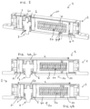
- Figs. 8-9 is shown another embodiment of a pivot hinge 300 according to the invention.
- the pivot hinge 300 has a pivot pin member 303 for pivotally connecting a pivotal door leaf with a structural element, the door leaf having an upper edge, lower edge, an inner side edge and an outer side edge, and the pivot pin member 303 defining a vertical pivot axis P A for the door leaf.
- the pivot hinge 300 comprises a casing 302 configured to be mounted to either the door leaf or the structural element, for example to the lower edge of the door leaf, the pivot pin member 303 being configured to be fixed to the other of the door leaf or the structural element.
- the casing comprises an upper part 302a and a lower part 302b.
- the pivot pin member 300 can be seen in Figs. 8-9 to have a cam 304, the pivot hinge 300 comprising a first cam follower 305 on a first side of the pivot pin member 303 and a second cam follower 306 on a second side of the pivot pin member 303 opposite the first side.
- the cam followers 305, 306, are both movable in a radial direction relative to the cam 304.
- the pivot hinge 300 is suitable to be mounted to the lower edge of the door leaf, e.g. in a corner region between the inner side edge and the lower edge of the pivotal door leaf.
- the pivot hinge 300 may be mounted such that the hinge 300 extends along the lower edge of the pivotal door leaf and the first cam follower 305 is located near the inner side edge of the door leaf.
- the pivot hinge 300 comprises spring arrangements 330, 430 adapted to urge a cam follower 305 or 306 against the cam 304.
- the spring arrangements 330, 430 here each comprise a coil spring.
- the coil springs are arranged side-by-side, separated by block 385.
- the cam 304 has recesses 308, 309 configured to receive one or both of the cam followers 305, 306 to form holding positions for the door leaf, e.g. in opened and/or closed positions of the door leaf, or positions therebetween.
- the spring arrangements 330, 430 are arranged side-by-side within the casing 302.
- the cam followers 305, 306 are provided with bearings 305b and 306b respectively.
- the pivot hinge 300 further comprises a slidable reciprocating member being arranged within the casing 302 and being movably mounted therein.
- the slidable reciprocating member has a first end part 321 and a second end part 322 that are rigidly connected to one another.
- the slidable reciprocating member further has a third end part 422 that is rigidly connected to the first end part 321. As such the slidable reciprocating member has a predetermined, fixed length.
- the first end part 321 is coupled with the first cam follower 305,
- the spring arrangement 330 is arranged between the second cam follower 306 and the second end part 322, and the spring arrangement 430 is arranged between the second cam follower 306 and the third end part 422, such that the spring arrangement 330 and/or spring arrangement 430 urge both cam followers 305, 306 against the cam 304 .
- the slidable reciprocating member has tension rod 324 for connecting the first end part 321 and the second end part 322, and the slidable reciprocating member has tension rod 323 for connecting the first end part 321 and the further end part 422
- the slidable reciprocating member has sliding faces, e.g. 370, that are in sliding engagement with the casing 302.
- the surfaces being in sliding engagement may be treated with a surface treatment, for example a friction reducing coating.
- the casing 302 may be provided with inner ribs 350 to slidably support the slidable reciprocating member. These inner ribs 350 may be provided on a lower part 302a of the casing 302 (e.g. shown in Fig. 8 ) and/or on an upper part 302a of the casing 2.
- the lower part 302a of the casing is provided with a recess, here demarcated between the ribs 350, so as to facilitate the sliding movement of the slidable reciprocating member.
- the slidable reciprocating member may be in sliding engagement with - i.e. direct contact with - the ribs 350 and/or the recess, or the slidable reciprocating member may slide in such a manner that there is no direct contact between the slidable reciprocating member and the ribs 350 and/or the recess.
- the pivot hinge 300 further comprises a slidable guide member 340 that is movably mounted within the slidable reciprocating member, the slidable guide member 340 being coupled with the second cam follower 306, and the spring arrangements 330, 340 being arranged between the slidable guide member 340 and the respective end parts 322, 422.
- first cam follower 305 is retained on the first end part 321, and the second cam follower 306 is retained on the slidable guide member 340.
- the slidable guide member 340 is elongate and has two bores in which the tension rods 323, 324 are received.
- Tension rods 323, 324 are received in a recess 304c between upper part 304a and lower part 304b of the cam 304.
- Block 385 is arranged at an end of the casing 302 on the same side of the pivot pin member 303 as first end part 321.
- Block 380 is arranged at the opposite end of the casing 302.
Landscapes
- Engineering & Computer Science (AREA)
- Mechanical Engineering (AREA)
- Closing And Opening Devices For Wings, And Checks For Wings (AREA)
Priority Applications (7)
| Application Number | Priority Date | Filing Date | Title |
|---|---|---|---|
| PL22171124.5T PL4273360T3 (pl) | 2022-05-02 | 2022-05-02 | Zawias obrotowy i obrotowe skrzydło drzwiowe |
| EP22171124.5A EP4273360B1 (fr) | 2022-05-02 | 2022-05-02 | Charnière pivotante et vantail de porte pivotant |
| ES22171124T ES3039264T3 (en) | 2022-05-02 | 2022-05-02 | Pivot hinge and pivotal door leaf |
| AU2023264193A AU2023264193A1 (en) | 2022-05-02 | 2023-04-19 | A pivot hinge and pivotal door leaf. |
| PCT/EP2023/060109 WO2023213541A1 (fr) | 2022-05-02 | 2023-04-19 | Charnière à pivot et battant de porte pivotant |
| US18/856,893 US20250263961A1 (en) | 2022-05-02 | 2023-04-19 | A pivot hinge and pivotal door leaf |
| CN202380036886.2A CN119110869A (zh) | 2022-05-02 | 2023-04-19 | 枢轴铰链和枢转门扇 |
Applications Claiming Priority (1)
| Application Number | Priority Date | Filing Date | Title |
|---|---|---|---|
| EP22171124.5A EP4273360B1 (fr) | 2022-05-02 | 2022-05-02 | Charnière pivotante et vantail de porte pivotant |
Publications (3)
| Publication Number | Publication Date |
|---|---|
| EP4273360A1 true EP4273360A1 (fr) | 2023-11-08 |
| EP4273360C0 EP4273360C0 (fr) | 2025-07-02 |
| EP4273360B1 EP4273360B1 (fr) | 2025-07-02 |
Family
ID=81579503
Family Applications (1)
| Application Number | Title | Priority Date | Filing Date |
|---|---|---|---|
| EP22171124.5A Active EP4273360B1 (fr) | 2022-05-02 | 2022-05-02 | Charnière pivotante et vantail de porte pivotant |
Country Status (7)
| Country | Link |
|---|---|
| US (1) | US20250263961A1 (fr) |
| EP (1) | EP4273360B1 (fr) |
| CN (1) | CN119110869A (fr) |
| AU (1) | AU2023264193A1 (fr) |
| ES (1) | ES3039264T3 (fr) |
| PL (1) | PL4273360T3 (fr) |
| WO (1) | WO2023213541A1 (fr) |
Families Citing this family (1)
| Publication number | Priority date | Publication date | Assignee | Title |
|---|---|---|---|---|
| JP2024516036A (ja) * | 2021-05-06 | 2024-04-11 | コルコム グループ エス.アール.エル. | ドア、リーフなどの制御された回転移動のためのシステム |
Citations (2)
| Publication number | Priority date | Publication date | Assignee | Title |
|---|---|---|---|---|
| DE102010022047A1 (de) * | 2009-12-01 | 2011-06-09 | Dorma Gmbh + Co. Kg | Türschließer mit Nockentrieb |
| DE102015206151A1 (de) | 2015-04-07 | 2016-10-13 | Ford Global Technologies, Llc | Vorrichtung zur Energierückgewinnung an einem Verbrennungsmotor mit Abgasturbolader als Wärmequelle für einen Dampfkraftmaschinenkreislauf und Verfahren zum Betrieb der Vorrichtung |
Family Cites Families (11)
| Publication number | Priority date | Publication date | Assignee | Title |
|---|---|---|---|---|
| US3174177A (en) * | 1961-11-06 | 1965-03-23 | Erling P Bugge | Door closer |
| GB1174327A (en) | 1966-09-24 | 1969-12-17 | Zd Y Umelecke Kovovyroby Narod | Improvements in or relating to Door Closers. |
| DE3345004A1 (de) * | 1983-12-13 | 1985-06-13 | Dorma-Baubeschlag Gmbh & Co Kg, 5828 Ennepetal | Obentuerschliesser |
| DE4041824C1 (fr) * | 1990-12-24 | 1992-06-11 | Dorma Gmbh + Co. Kg, 5828 Ennepetal, De | |
| US5901412A (en) * | 1996-01-30 | 1999-05-11 | Dorma Gmbh + Co. Kg | Top-mounted door closer |
| KR200324642Y1 (ko) * | 2003-06-03 | 2003-08-25 | 박형태 | 플로어 힌지 |
| US20110197391A1 (en) * | 2010-02-12 | 2011-08-18 | Rick Yu | Automatic door closer structure |
| NL2005520C2 (nl) * | 2010-10-14 | 2011-09-13 | Estem B V | Scharnier voor een paneeldeur, in het bijzonder voor een koelmeubel. |
| DE202015006151U1 (de) * | 2015-09-02 | 2016-12-07 | Gretsch-Unitas GmbH Baubeschläge | Schließvorrichtung zum Schließen eines Türflügels |
| ES2865059T3 (es) * | 2019-01-16 | 2021-10-14 | Dormakaba Deutschland Gmbh | Accionador de puerta |
| CN221546714U (zh) * | 2023-12-11 | 2024-08-16 | 东莞力督门控设备有限公司 | 窄边框门用360度旋转凸轮液压闭门器 |
-
2022
- 2022-05-02 ES ES22171124T patent/ES3039264T3/es active Active
- 2022-05-02 PL PL22171124.5T patent/PL4273360T3/pl unknown
- 2022-05-02 EP EP22171124.5A patent/EP4273360B1/fr active Active
-
2023
- 2023-04-19 WO PCT/EP2023/060109 patent/WO2023213541A1/fr not_active Ceased
- 2023-04-19 US US18/856,893 patent/US20250263961A1/en active Pending
- 2023-04-19 AU AU2023264193A patent/AU2023264193A1/en active Pending
- 2023-04-19 CN CN202380036886.2A patent/CN119110869A/zh active Pending
Patent Citations (2)
| Publication number | Priority date | Publication date | Assignee | Title |
|---|---|---|---|---|
| DE102010022047A1 (de) * | 2009-12-01 | 2011-06-09 | Dorma Gmbh + Co. Kg | Türschließer mit Nockentrieb |
| DE102015206151A1 (de) | 2015-04-07 | 2016-10-13 | Ford Global Technologies, Llc | Vorrichtung zur Energierückgewinnung an einem Verbrennungsmotor mit Abgasturbolader als Wärmequelle für einen Dampfkraftmaschinenkreislauf und Verfahren zum Betrieb der Vorrichtung |
Also Published As
| Publication number | Publication date |
|---|---|
| WO2023213541A1 (fr) | 2023-11-09 |
| ES3039264T3 (en) | 2025-10-20 |
| PL4273360T3 (pl) | 2025-11-12 |
| EP4273360C0 (fr) | 2025-07-02 |
| AU2023264193A1 (en) | 2024-10-24 |
| US20250263961A1 (en) | 2025-08-21 |
| CN119110869A (zh) | 2024-12-10 |
| EP4273360B1 (fr) | 2025-07-02 |
Similar Documents
| Publication | Publication Date | Title |
|---|---|---|
| EP3259425B1 (fr) | Système de levage pour battants de porte de meuble | |
| US11603693B2 (en) | Furniture hinge for upward-opening cabinet doors | |
| CN108699872B (zh) | 用于家具的门扇的具有弹性打开部件的铰链 | |
| EP3289157B9 (fr) | Charnière ralentie pour meuble | |
| US10030427B2 (en) | Compact hinge apparatus and method of use | |
| US9422757B2 (en) | Hinge for the controlled rotatable movement of a door, in particular a glass door | |
| EP2315896B1 (fr) | Structure de porte avec charnieres a pivot a fermeture automatique integrees dans un panneau de porte | |
| JP2016205128A (ja) | 摺動ドアのためのガイドデバイス | |
| EP4273360A1 (fr) | Charnière pivotante et vantail de porte pivotant | |
| EP3662125A1 (fr) | Charnière dotée de dispositif d'ouverture pour meubles | |
| CN113585899B (zh) | 一种缓冲安全自动关门合页 | |
| US20200115943A1 (en) | Hinge for the Rotatable Movement of a Door, a Shutter or the Like | |
| EP2872717B1 (fr) | Charnière pour le mouvement rotatif d'une porte en particulier porte renforcee | |
| US6000796A (en) | Slidably resilient hinge for eyeglass frames | |
| RU2019137202A (ru) | Механизм для перемещения мебельной дверцы | |
| CN107923203B (zh) | 铰链和具有铰链的护板 | |
| CN211736807U (zh) | 滑轮支撑装置 | |
| US8465066B2 (en) | Swivel bearing for a pressing mechanism of a closing device | |
| KR101268957B1 (ko) | 댐핑 장치 | |
| EP3056644A1 (fr) | Dispositif de charnière réglable et compact | |
| US20220316249A1 (en) | Hinge for the rotatable movement of a door, a leaf or the like and system for fixing the latter to a stationary supporting structure | |
| WO2018002805A2 (fr) | Charnière pour le mouvement rotatif d'une porte ou d'un élément de fermeture similaire | |
| KR200483996Y1 (ko) | 가구 힌지용 어댑터 | |
| WO2025219881A1 (fr) | Charnière pour le mouvement rotatif d'un élément de fermeture de verre tel qu'une porte, un battant ou similaire |
Legal Events
| Date | Code | Title | Description |
|---|---|---|---|
| PUAI | Public reference made under article 153(3) epc to a published international application that has entered the european phase |
Free format text: ORIGINAL CODE: 0009012 |
|
| STAA | Information on the status of an ep patent application or granted ep patent |
Free format text: STATUS: THE APPLICATION HAS BEEN PUBLISHED |
|
| AK | Designated contracting states |
Kind code of ref document: A1 Designated state(s): AL AT BE BG CH CY CZ DE DK EE ES FI FR GB GR HR HU IE IS IT LI LT LU LV MC MK MT NL NO PL PT RO RS SE SI SK SM TR |
|
| STAA | Information on the status of an ep patent application or granted ep patent |
Free format text: STATUS: REQUEST FOR EXAMINATION WAS MADE |
|
| 17P | Request for examination filed |
Effective date: 20240503 |
|
| RBV | Designated contracting states (corrected) |
Designated state(s): AL AT BE BG CH CY CZ DE DK EE ES FI FR GB GR HR HU IE IS IT LI LT LU LV MC MK MT NL NO PL PT RO RS SE SI SK SM TR |
|
| RIC1 | Information provided on ipc code assigned before grant |
Ipc: E05F 1/12 20060101ALN20241126BHEP Ipc: E05D 15/54 20060101ALI20241126BHEP Ipc: E05D 11/10 20060101ALI20241126BHEP Ipc: E05D 7/081 20060101AFI20241126BHEP |
|
| GRAP | Despatch of communication of intention to grant a patent |
Free format text: ORIGINAL CODE: EPIDOSNIGR1 |
|
| STAA | Information on the status of an ep patent application or granted ep patent |
Free format text: STATUS: GRANT OF PATENT IS INTENDED |
|
| RIC1 | Information provided on ipc code assigned before grant |
Ipc: E05F 1/12 20060101ALN20241219BHEP Ipc: E05D 15/54 20060101ALI20241219BHEP Ipc: E05D 11/10 20060101ALI20241219BHEP Ipc: E05D 7/081 20060101AFI20241219BHEP |
|
| INTG | Intention to grant announced |
Effective date: 20250108 |
|
| GRAS | Grant fee paid |
Free format text: ORIGINAL CODE: EPIDOSNIGR3 |
|
| GRAA | (expected) grant |
Free format text: ORIGINAL CODE: 0009210 |
|
| STAA | Information on the status of an ep patent application or granted ep patent |
Free format text: STATUS: THE PATENT HAS BEEN GRANTED |
|
| AK | Designated contracting states |
Kind code of ref document: B1 Designated state(s): AL AT BE BG CH CY CZ DE DK EE ES FI FR GB GR HR HU IE IS IT LI LT LU LV MC MK MT NL NO PL PT RO RS SE SI SK SM TR |
|
| REG | Reference to a national code |
Ref country code: GB Ref legal event code: FG4D |
|
| REG | Reference to a national code |
Ref country code: CH Ref legal event code: EP |
|
| REG | Reference to a national code |
Ref country code: DE Ref legal event code: R096 Ref document number: 602022016693 Country of ref document: DE |
|
| REG | Reference to a national code |
Ref country code: IE Ref legal event code: FG4D |
|
| U01 | Request for unitary effect filed |
Effective date: 20250704 |
|
| U07 | Unitary effect registered |
Designated state(s): AT BE BG DE DK EE FI FR IT LT LU LV MT NL PT RO SE SI Effective date: 20250711 |
|
| REG | Reference to a national code |
Ref country code: ES Ref legal event code: FG2A Ref document number: 3039264 Country of ref document: ES Kind code of ref document: T3 Effective date: 20251020 |
|
| REG | Reference to a national code |
Ref country code: GR Ref legal event code: EP Ref document number: 20250401976 Country of ref document: GR Effective date: 20251112 |
|
| PG25 | Lapsed in a contracting state [announced via postgrant information from national office to epo] |
Ref country code: IS Free format text: LAPSE BECAUSE OF FAILURE TO SUBMIT A TRANSLATION OF THE DESCRIPTION OR TO PAY THE FEE WITHIN THE PRESCRIBED TIME-LIMIT Effective date: 20251102 |
|
| PG25 | Lapsed in a contracting state [announced via postgrant information from national office to epo] |
Ref country code: NO Free format text: LAPSE BECAUSE OF FAILURE TO SUBMIT A TRANSLATION OF THE DESCRIPTION OR TO PAY THE FEE WITHIN THE PRESCRIBED TIME-LIMIT Effective date: 20251002 |
|
| PG25 | Lapsed in a contracting state [announced via postgrant information from national office to epo] |
Ref country code: HR Free format text: LAPSE BECAUSE OF FAILURE TO SUBMIT A TRANSLATION OF THE DESCRIPTION OR TO PAY THE FEE WITHIN THE PRESCRIBED TIME-LIMIT Effective date: 20250702 |
|
| PG25 | Lapsed in a contracting state [announced via postgrant information from national office to epo] |
Ref country code: CZ Free format text: LAPSE BECAUSE OF FAILURE TO SUBMIT A TRANSLATION OF THE DESCRIPTION OR TO PAY THE FEE WITHIN THE PRESCRIBED TIME-LIMIT Effective date: 20250702 |
|
| PG25 | Lapsed in a contracting state [announced via postgrant information from national office to epo] |
Ref country code: RS Free format text: LAPSE BECAUSE OF FAILURE TO SUBMIT A TRANSLATION OF THE DESCRIPTION OR TO PAY THE FEE WITHIN THE PRESCRIBED TIME-LIMIT Effective date: 20251002 |
|
| PG25 | Lapsed in a contracting state [announced via postgrant information from national office to epo] |
Ref country code: SM Free format text: LAPSE BECAUSE OF FAILURE TO SUBMIT A TRANSLATION OF THE DESCRIPTION OR TO PAY THE FEE WITHIN THE PRESCRIBED TIME-LIMIT Effective date: 20250702 |