EP4273561A1 - Borne électrique à ressort pour borne enfichable de compteur - Google Patents
Borne électrique à ressort pour borne enfichable de compteur Download PDFInfo
- Publication number
- EP4273561A1 EP4273561A1 EP23171119.3A EP23171119A EP4273561A1 EP 4273561 A1 EP4273561 A1 EP 4273561A1 EP 23171119 A EP23171119 A EP 23171119A EP 4273561 A1 EP4273561 A1 EP 4273561A1
- Authority
- EP
- European Patent Office
- Prior art keywords
- contact
- terminal
- spring contact
- meter
- clamping
- Prior art date
- Legal status (The legal status is an assumption and is not a legal conclusion. Google has not performed a legal analysis and makes no representation as to the accuracy of the status listed.)
- Granted
Links
Images


Classifications
-
- G—PHYSICS
- G01—MEASURING; TESTING
- G01R—MEASURING ELECTRIC VARIABLES; MEASURING MAGNETIC VARIABLES
- G01R11/00—Electromechanical arrangements for measuring time integral of electric power or current, e.g. of consumption
- G01R11/02—Constructional details
- G01R11/04—Housings; Supporting racks; Arrangements of terminals
-
- G—PHYSICS
- G01—MEASURING; TESTING
- G01R—MEASURING ELECTRIC VARIABLES; MEASURING MAGNETIC VARIABLES
- G01R1/00—Details of instruments or arrangements of the types included in groups G01R5/00 - G01R13/00 and G01R31/00
- G01R1/20—Modifications of basic electric elements for use in electric measuring instruments; Structural combinations of such elements with such instruments
-
- H—ELECTRICITY
- H01—ELECTRIC ELEMENTS
- H01R—ELECTRICALLY-CONDUCTIVE CONNECTIONS; STRUCTURAL ASSOCIATIONS OF A PLURALITY OF MUTUALLY-INSULATED ELECTRICAL CONNECTING ELEMENTS; COUPLING DEVICES; CURRENT COLLECTORS
- H01R11/00—Individual connecting elements providing two or more spaced connecting locations for conductive members which are, or may be, thereby interconnected, e.g. end pieces for wires or cables supported by the wire or cable and having means for facilitating electrical connection to some other wire, terminal, or conductive member, blocks of binding posts
- H01R11/03—Individual connecting elements providing two or more spaced connecting locations for conductive members which are, or may be, thereby interconnected, e.g. end pieces for wires or cables supported by the wire or cable and having means for facilitating electrical connection to some other wire, terminal, or conductive member, blocks of binding posts characterised by the relationship between the connecting locations
- H01R11/05—Individual connecting elements providing two or more spaced connecting locations for conductive members which are, or may be, thereby interconnected, e.g. end pieces for wires or cables supported by the wire or cable and having means for facilitating electrical connection to some other wire, terminal, or conductive member, blocks of binding posts characterised by the relationship between the connecting locations the connecting locations having different types of direct connections
-
- H—ELECTRICITY
- H01—ELECTRIC ELEMENTS
- H01R—ELECTRICALLY-CONDUCTIVE CONNECTIONS; STRUCTURAL ASSOCIATIONS OF A PLURALITY OF MUTUALLY-INSULATED ELECTRICAL CONNECTING ELEMENTS; COUPLING DEVICES; CURRENT COLLECTORS
- H01R13/00—Details of coupling devices of the kinds covered by groups H01R12/70 or H01R24/00 - H01R33/00
- H01R13/02—Contact members
- H01R13/10—Sockets for co-operation with pins or blades
- H01R13/11—Resilient sockets
- H01R13/113—Resilient sockets co-operating with pins or blades having a rectangular transverse section
-
- H—ELECTRICITY
- H01—ELECTRIC ELEMENTS
- H01R—ELECTRICALLY-CONDUCTIVE CONNECTIONS; STRUCTURAL ASSOCIATIONS OF A PLURALITY OF MUTUALLY-INSULATED ELECTRICAL CONNECTING ELEMENTS; COUPLING DEVICES; CURRENT COLLECTORS
- H01R9/00—Structural associations of a plurality of mutually-insulated electrical connecting elements, e.g. terminal strips or terminal blocks; Terminals or binding posts mounted upon a base or in a case; Bases therefor
- H01R9/22—Bases, e.g. strip, block, panel
- H01R9/24—Terminal blocks
- H01R9/2491—Terminal blocks structurally associated with plugs or sockets
-
- G—PHYSICS
- G01—MEASURING; TESTING
- G01R—MEASURING ELECTRIC VARIABLES; MEASURING MAGNETIC VARIABLES
- G01R1/00—Details of instruments or arrangements of the types included in groups G01R5/00 - G01R13/00 and G01R31/00
- G01R1/02—General constructional details
- G01R1/04—Housings; Supporting members; Arrangements of terminals
-
- H—ELECTRICITY
- H01—ELECTRIC ELEMENTS
- H01R—ELECTRICALLY-CONDUCTIVE CONNECTIONS; STRUCTURAL ASSOCIATIONS OF A PLURALITY OF MUTUALLY-INSULATED ELECTRICAL CONNECTING ELEMENTS; COUPLING DEVICES; CURRENT COLLECTORS
- H01R4/00—Electrically-conductive connections between two or more conductive members in direct contact, i.e. touching one another; Means for effecting or maintaining such contact; Electrically-conductive connections having two or more spaced connecting locations for conductors and using contact members penetrating insulation
- H01R4/28—Clamped connections, spring connections
- H01R4/30—Clamped connections, spring connections utilising a screw or nut clamping member
- H01R4/34—Conductive members located under head of screw
Definitions
- the present invention relates to an electrical spring contact terminal for a meter plug-in terminal, which is used to connect an electricity meter to the electrical power supply network.
- the invention also relates to a meter plug-in terminal with such a spring contact terminal.
- Meter plug-in terminals are used to ensure that electricity meters can be changed very quickly and without interruptions in power or voltage.
- meter connection terminals which are screwed on the mains side and meter side
- so-called meter plug-in terminals only the mains side is usually screwed on during the initial installation.
- plug connection on the side that houses the electricity meter. Plug-in connections have proven to be advantageous due to subsequent electricity meter changes for reasons of workload and work safety.
- meter connection terminals have to be screwed under tension on the meter side, which on the one hand means increased danger for the assembly worker and, on the other hand, is prone to errors because the screws can be forgotten to tighten. If you accidentally forget to tighten frame clamps or extruded blocks, there is a risk of a very poor electrical connection and therefore the risk of a so-called "hot spot", or arc, and in the worst case scenario, this could become a possible cause of fire.
- a typical meter plug-in terminal points to one mains connection side Clamp connection elements for power cables on and on a meter connection side that is usually opposite the mains connection side. Clamp connection elements for the contact pins of the electricity meter. While the power cables are usually connected to the meter plug-in terminal using a screw connection, the electricity meter is inserted with its contact pins into spring contacts provided on the meter plug-in terminal. The spring contacts thus form the electrical connection to the electricity meter.
- a bridging device When replacing the electricity meter, a bridging device is plugged onto the meter plug-in terminal, which enables the meter to be replaced without interrupting the power supply. During the replacement, "uncounted" current flows through the jumper plug.
- a bridging device with electrical conductor bridges for bridging the electricity meter connected to the electrical power network when the electricity meter is changed is known in particular from the standard DIN VDE 0603-3-3:2020-08, paragraph 9.101, figure 101.
- Meter connection terminals that require screwing on both the network and meter sides are, for example, from the DE 102 16 913 A1 and the CH 711 633 B1 known.
- Meter plug-in terminals into which the electricity meter can be easily plugged in, are, for example DE 101 63 620 B4 , DE 2 256 373 A1 and DE 41 13 328 A disclosed.
- the meter plug-in terminals each have spring contact terminals constructed in several parts. The clamping effect is created by a spiral spring that is arranged between the two legs of the clamp.
- Such meter plug-in terminals have the advantage over meter connection terminals that they do not have to be screwed under tension and the chances of incorrect manipulation are significantly lower.
- EP 1 586 908 A1 US 2017/0040715 A1 , US 4,798,546 , US 4,643,510 , DE 203 15 898 U , DE 10 2015 013 011 A1 and EP 1 901 398 A1 .
- the disadvantage of many currently available meter plug-in terminals is that the spring contacts are dimensioned and designed in such a way that the current strength is limited, for example to 63 amps.
- the well-known meter plug-in terminals are often tulip-shaped Spring contact terminals are used to contact one of the contact pins of the electricity meter. Spring contacts in the form of such contact tulips can be manufactured relatively easily.
- the connection for the current from the contact tulip to the frame terminal, which is used to connect the meter plug-in terminal to the power supply network often forms the limiting component element, which makes it impossible to use the meter plug-in terminal for larger current intensities.
- claim 8 specifies a meter plug-in terminal with such a spring contact terminal. Further embodiments are specified in the dependent claims.
- the spring contact clamp also has a first transfer section, which electrically and mechanically connects the first clamping leg to the contact tab at a distance from the connecting section, and a second transfer section, which electrically and mechanically connects the second clamping leg to the contact tab at a distance from the connecting section.
- the electricity can flow from the two Clamping legs are each routed separately to the contact tab. Due to the separate, ie double, transmission, the total material cross-section used to conduct electricity between the contact tulip and the contact tab can be significantly increased and, in particular, can be coordinated with the design of the contact tulip and the contact tab. The connection between the contact tulip and the contact tab therefore does not form the limiting component element with regard to the current conduction. Due to the two transfer sections, the spring contact terminal can therefore be designed particularly well and with relatively little material expenditure, even for high current intensities.
- the spring contact terminal is preferably designed for nominal currents up to 80 amps and peak loads up to 128 amps.
- the transfer sections preferably serve not only to improve the current transmission from the contact tulip to the contact tab. They also advantageously serve to influence and in particular adjust the clamping force of the contact tulip. Since the transfer sections are each attached to the clamping leg at a distance from the connecting section, the clamping force or spring effect of the clamping legs is significantly influenced by the transfer sections.
- the transfer sections can be connected to one another in particular and preferably in the area of the contact tab, in order not only to combine the respective currents, but also to define the clamping force of the contact tulip and to pre-stress it.
- the contact tulip is preferably used not only for contacting and clamping a contact pin of the electricity meter on both sides, but also for contacting and clamping on both sides of a conductor element of a bridging device.
- the contact tulip is preferably designed so that a contact pin of the electricity meter is inserted into the contact tulip from a first direction and a conductor element of the bridging device from a different second direction, the first and second directions advantageously being at right angles to one another.
- the contact tulip can be designed so that when used as intended, the contact pin of the electricity meter is advanced in the longitudinal direction, ie parallel along the connecting section, between the two clamping legs, and that the conductor element of the bridging device is advanced essentially parallel to the two clamping legs towards the connecting section .
- the conductor element of the bridging device By advancing the conductor element of the bridging device into the area between the two clamping legs, these are preferably pressed apart and thereby reduce the Clamping force exerted on the contact pin of the electricity meter.
- the electricity meter can then be easily pulled out of the spring contact terminal after inserting the bridging device.
- the power line passes seamlessly from the electricity meter to the bridging device and can therefore be guaranteed without interruption.
- the electricity meter which can also be a smart meter, can therefore be replaced easily and without interrupting the power supply.
- the contact tulip with its two clamping legs connected to one another via the connecting section therefore preferably has a U-shaped shape overall.
- the two legs are preferably slightly inclined towards each other in the unloaded state. Depressions and/or grooves can be formed on the mutually facing inner surfaces of the clamping legs in order to improve the clamping of the contact pin of the electricity meter and/or the conductor element of the bridging device.
- the contact tulip advantageously has a constriction near the free ends of the two clamping legs in order to then form a V-shaped receptacle from this towards the free ends.
- the narrowing can improve the clamping effect and contacting of the conductor element of the bridging device, which is advantageously inserted from above.
- Local elevations and/or depressions provided in the area of the constriction, for example in the form of bulges, can further improve the contacting of the conductor element.
- the V-shaped receptacle can make it easier to insert the conductor element.
- the contact tab advantageously has a rectangular shape. It is preferably designed so that a contact element of the power supply network is clamped between the contact tab and a clamping element, such as in particular a clamping screw. Alternatively, it can also be designed so that a clamping element, such as in particular a clamping screw, acts directly on the contact tab in order to clamp a contact element of the power supply network between the contact tab and another counter-element.
- the spring contact terminal is preferably designed for bridging with a standardized bridging device, the standard corresponding to DIN VDE 0603-3-3:2020-08, paragraph 9.101, figure 101.
- first clamping leg and the second clamping leg each extend along a main direction away from the connecting section, which is perpendicular to a contacting surface formed by the contact tab. While the clamping legs, for example, extend essentially upwards in the vertical direction from the connecting section, the contact tab therefore preferably forms a contacting surface that lies in a horizontal plane. This has the advantage that the contact pin of the electricity meter and the contact element of the power supply network can then be inserted into the spring contact terminal from opposite sides during assembly, which proves to be advantageous in practice, particularly in terms of space requirements.
- the spring contact terminal is preferably designed as a whole in one piece. This means that the spring contact terminal is not only particularly easy to manufacture, but also ensures optimal current conduction at all times.
- the contact tab is preferably twice as thick as the first and second clamping legs.
- the material cross section of the contact tab is therefore adapted to the contact tulip with regard to current conduction. Since the contact tab is usually designed to be arranged and clamped in a box terminal, twice the thickness of the contact tab also results in an increased current-conducting cross section towards the box terminal. If the spring contact clamp is made as a whole from a sheet of metal (see below), such a thickness of the contact tab that is twice as large can be achieved particularly easily by simply placing two sheet metal sections on top of each other when producing the spring contact clamp, which then together form the contact tab.
- the spring contact terminal is made as a whole from a sheet metal. This makes the production of the spring contact terminals particularly simple and cost-effective. It is particularly advantageous if the essential shape of the spring contact terminal can also be produced by simply punching out, cutting, folding and/or bending an originally flat sheet of metal.
- the contact tab is preferably designed twice by means of two sheet metal sections placed one above the other. It is particularly preferred if each of the sheet metal sections has one of the transfer sections is connected. In this case, the clamping characteristics of the contact tulip can be adjusted particularly well and precisely by fastening the two superimposed sheet metal sections to one another. An embodiment in which the two sheet metal sections are connected to one another at a clinching point has proven to be particularly advantageous.
- the enforcement joining point is preferably oval.
- the present invention also relates to a meter plug-in terminal for connecting an electricity meter to the electrical power supply network, having at least one spring contact terminal, which is designed according to the above information.
- the meter plug-in terminal preferably has not just one, but a plurality of such spring contact terminals. An embodiment with exactly 7 such spring contact terminals is particularly preferred.
- the meter plug-in terminal preferably has an equal number or, which is preferred, a larger number of frame terminals, in particular steel frame terminals. While the spring contact terminals form the connections to the electricity meter, the box terminals then form the connections to the power supply network.
- the steel frame clamp which is preferably additionally present, can be used in particular to connect a second neutral conductor.
- the frame terminals are preferably used to clamp and mutually contact the contact tab and a contact element of the power supply network.
- the meter plug-in terminal usually has a housing in which the one or more spring contact terminals are accommodated.
- the housing preferably has bridging openings, each of which serves to insert a conductor element of a bridging device.
- the conductor elements can preferably be inserted through the bridging openings into the contact tulips of the spring contact terminals. It is particularly advantageous for safety reasons if the bridging openings are arranged within a recess provided on the housing, which makes it impossible to touch the conductor elements of the bridging device from the outside as soon as the conductor elements contact the spring contact terminals. The person operating the bridging device is therefore not exposed to the risk of touching a conductor bridge that is under electrical voltage and thus being injured.
- the housing can in particular be made from a plastic using an injection molding process.
- the housing advantageously has a housing opening, which can be used, for example, to insert the spring contact terminals into the interior of the housing during production.
- the housing opening can preferably be closed by means of a base plate.
- the base plate can be made from a plastic that conducts heat particularly well compared to the housing.
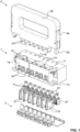
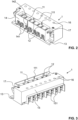
- FIG. 1 to 18 An embodiment of a meter plug-in terminal according to the invention is shown in various views, including the spring contact terminals 3 accommodated therein and a matching bridging device 5.
- the Figure 1 shows the open meter plug-in terminal with the housing 1, the base plate 2 and the spring contact terminals 3 and steel frame terminals 4 arranged therein.
- the housing 1 Inside the housing 1 there are 7 electrical spring contact terminals 3, each of which has a contact tulip 31, which serves on the one hand to hold a bridging device 5 and on the other hand to hold a contact pin of the electricity meter.
- the electricity meter is not shown in the figures. Electricity meters and their design are well known to those skilled in the art.
- the spring contact terminals 3 are arranged in the housing 1 in such a way that their contact tulips 31 are each accessible to the electricity meter from a meter connection side 14 of the housing 1.
- the housing 1 has corresponding meter-side connection openings 141, through which a contact element of the electricity meter can be pushed into a contact tulip 31.
- the meter-side connection openings 141 are each formed by a rectangular, chamfered opening and are therefore designed to accommodate a meter contact pin with a square and round cross-section.
- the chamfers are used to offset or compensate for position errors of the contact pins mounted on the electricity meter.
- the steel frame clamps 4 Facing a power connection side 15 of the housing 1, the steel frame clamps 4 are arranged inside the housing 1.
- Each steel frame clamp 4 has a clamping screw 41.
- a total of 8 steel frame clamps 4 are provided, with six of the steel frame clamps serving for the three phases, i.e. two each for supplying and discharging the electricity to the electricity meter.
- Two of the steel frame terminals 4 are used for the neutral conductor connection.
- the steel frame terminals 4 On the side facing away from the power supply network, the steel frame terminals 4 each contact a contact tab 37 of a respective spring contact terminal 3 which is integrally connected to the contact tulip 31.
- the steel frame terminals 4 thereby form an electrical connection between the steel frame terminals 4 and the power supply network.
- the bridging device 5 has three electrical conductor bridges 51, each of which has two plug-in elements arranged parallel to one another, which can each be inserted from above into a contact tulip 31 for bridging purposes.
- the plug-in elements of the conductor bridges 51 thus form conductor elements with which the current phases can be bridged or short-circuited, i.e. each of the conductor bridges 51 serves to supply or discharge one phase.
- the bridging device 5 has a single protruding neutral conductor plug element 52 for the neutral conductor, which does not need to be bridged. However, there are two outlets of the neutral conductor on the network side.
- the protruding plug-in elements of the conductor bridges 51 have the function of opening the contact tulips 31 so that the electricity meter with its 7 contact pins (2 per phase and a neutral conductor) can be easily replaced.
- the current flows via the conductor bridges 51 and not via the electricity meter.
- bridging openings 12 are provided on the top of the housing 1, which serve to insert the bridging device 5 with its conductor bridges 51 and its neutral conductor plug element 52 into the contact tulips 31.
- the bridging openings 12 are arranged within a recess 11 provided on the top of the housing.
- the recess 11, together with the bridging openings 12, forms the interface of the meter plug-in terminal to the bridging device 5.
- the recess 11 of the interface has the advantage that there is protection against contact when the bridging device 5 is inserted into the meter plug-in terminal.
- the recess 11 is designed in such a way that the conductor bridges 51 are no longer accessible from a part of a person's body when plugged in from the outside as soon as they are connected to the contact tulips 32 come into contact and are therefore potentially live.
- the recess 11 is preferably even designed in such a way that the conductor bridges 51 are no longer accessible from the outside before they come into contact with the contact tulips 32. Contact of live parts with a part of the operator's body can therefore be ruled out and is therefore impossible.
- cams 111 can be provided in the area of the recess 11 in order to only allow approved and correctly dimensioned bridging devices 5 and to exclude unsuitable ones.
- the handling of the bridging device 5 is made easier by means of a handle 55.
- a latching lock is provided.
- the bridging device 5 has protruding locking hooks 53, which are designed to hook onto the housing 1 when inserted.
- the latching lock can be released by means of pushbuttons 54 arranged on the side of the bridging device 5. By pressing the pushbuttons 54, the locking hooks 53 are pivoted outwards away from the housing 1.
- press-in nuts 17 are provided on the top of the housing, which are used to fasten covers that protect the meter plug-in terminal itself as long as no electricity meter with a corresponding cover is installed.
- the covers also offer protection against contact as long as an electricity meter with a meter cover is not installed.
- network-side connection openings 151 are formed on the housing 1, which enable access to the steel frame terminals 4 in order to connect the meter plug-in terminal to the power supply network.
- the network-side connection openings 151 are recessed on the housing 1.
- access to the clamping screws 41 is provided in the form of screw openings 16.
- the screw openings 16 are arranged on the top of the housing 1.
- the meter plug-in terminal can be attached to a house wall, for example Screw connections are made.
- the housing 1 has two recesses 13.
- the Figure 6 shows the meter plug-in terminal from below, i.e. as a top view of the side closed with the base plate 2.
- the recesses 13 provided on the housing 1, which are used to mount the meter plug-in terminal, are also clearly visible here.
- the Figure 7 shows the top of the meter plug-in terminal with the screw openings 16, the recess 11 and the bridging openings arranged within the recess 11.
- the contact tulips 31 are each formed by two clamping legs 32 and a connecting section 34.
- the two clamping legs 32 are each connected at one end in one piece to the connecting section 35 and extend from this essentially parallel to one another along a main extension direction upwards.
- the contact tulips 31 therefore have a U-shaped shape.
- the contact tulips 21 In the upper area of their free ends, the contact tulips 21 each have a constriction, which serves to contact the conductor elements of the bridging device to be inserted from above. From the constriction, the contact tulips 31 each form a V-shaped receptacle 35 upwards towards the free ends of the clamping legs 32, which simplify the insertion of the conductor elements of the bridging device.
- Each receptacle 35 is arranged directly below one of the bridging openings 12.
- the contact tabs 37 of the spring contact terminals 3 are each designed twice by means of two sheet metal sections placed one above the other.
- the Figure 9 also shows enforcement joining points 38, which are used for the mechanical and electrical connection of the two Sheet metal sections are used.
- the steel frame clamps 4 each form a clamping cage, in which a contact element of the power supply network can be clamped by means of the clamping screw 41 in such a way that it is contacted both by the contact tab 37 and by a part of the steel frame clamp 4.
- a round collar is molded onto the housing 1, which holds the clamping screw 41 in position on the screw head.
- a cylindrical pin is formed at each screw end, which holds the clamping screw 41 in position at its lower end. Even if the clamping screws 41 are completely unscrewed from the clamping cage, the collar and the cylindrical pin at the end of the screw prevent the screw from leaving the necessary position, or the central axis. The screws remain in position and screw themselves back into the clamping cage when rotated in opposite directions.
- the Figure 11 shows a cut in the in Figure 12 indicated level XI-XI through the contact tulips 31 and through a bridging device 5.
- the neutral conductor plug-in element 52 is not designed to be conductive since it has no current-carrying function , but only fulfills the function of opening the contact tulip 31 in order to facilitate the replacement of the electricity meter.
- the conductor bridges 51 are each screwed by means of a fastening screw 56 to the part of the bridging device 5, which is preferably made of a non-conductive plastic material and which also forms the handle 55.
- the Figures 13 - 18 show a spring contact terminal 3 alone in different views. From these figures it can be seen that the spring contact terminal 3 as a whole is made from a coherent, ie one-piece, sheet metal.
- the spring contact terminal 3 can be produced in particular by bending a preformed but flat sheet metal. Since two sheet metal sections are placed one on top of the other in the area of the contact tab 37, their thickness becomes twice as large as that of the clamping legs 32.
- the contact tab therefore has an optimal material cross section with regard to current conduction.
- the mechanical and electrical connection of the contact tulip 13 to the contact tab 37 takes place via two transfer sections 36.
- Each clamping leg 32 is connected in one piece to a transfer section 36.
- the current is thereby separated from the two clamping legs 32 to the contact tab or in the opposite direction directed.
- one of the transfer sections 36 merges into the lower sheet metal section of the contact tab 37
- the other transfer section 36 merges into the upper sheet metal section of the contact tab 37.
- the contact tab 37 extends in a plane that extends parallel to that of the connecting section 34, but is perpendicular to the plane along which the clamping legs 32 extend upwards in the main direction from the connecting section 34.
- the contact tulip 31 has locally embossed bulges 33 on both sides in the area of its upper constriction, which serve to improve the electrical contact with the conductor bridges 51 of the bridging device.
- the underside of the contact tab 37 is grooved, as in the Figure 18 is clearly visible.
- the contact tab 37 has an oval enforcement joint point 38, which holds the two sheet metal sections together in an optimal spring position and in particular ensures good behavior of the spring contact terminal 3 with regard to electrical and mechanical properties. Due to the spaced connection of the transfer sections 36 with the clamping legs 32 in combination with the fastening of the two sheet metal sections in the enforcement joint point 38, a precisely adjusted and uniform spring force of the contact tulip 31 can be achieved with the meter contact pin inserted therein. This ensures that the contact tulip 31 is in optimal contact with the meter pin, which enables an efficient and low-loss electrical connection to the electricity meter.
- the oval clinching point 38 is preferably produced according to the process known under the name OVAL- LOC® from BTM (Europe) Blech effettechnik GmbH.
Landscapes
- Physics & Mathematics (AREA)
- General Physics & Mathematics (AREA)
- Details Of Connecting Devices For Male And Female Coupling (AREA)
- Measuring Leads Or Probes (AREA)
- Connections Arranged To Contact A Plurality Of Conductors (AREA)
Applications Claiming Priority (1)
| Application Number | Priority Date | Filing Date | Title |
|---|---|---|---|
| CH00529/22A CH718347B1 (de) | 2022-05-06 | 2022-05-06 | Elektrische Federkontaktklemme für eine Zählersteckklemme. |
Publications (3)
| Publication Number | Publication Date |
|---|---|
| EP4273561A1 true EP4273561A1 (fr) | 2023-11-08 |
| EP4273561B1 EP4273561B1 (fr) | 2024-12-04 |
| EP4273561C0 EP4273561C0 (fr) | 2024-12-04 |
Family
ID=84418055
Family Applications (1)
| Application Number | Title | Priority Date | Filing Date |
|---|---|---|---|
| EP23171119.3A Active EP4273561B1 (fr) | 2022-05-06 | 2023-05-02 | Borne électrique à ressort pour borne enfichable de compteur |
Country Status (2)
| Country | Link |
|---|---|
| EP (1) | EP4273561B1 (fr) |
| CH (1) | CH718347B1 (fr) |
Families Citing this family (2)
| Publication number | Priority date | Publication date | Assignee | Title |
|---|---|---|---|---|
| CN116413489A (zh) * | 2023-05-25 | 2023-07-11 | 西安亮源电子科技有限公司 | 电力计量智能试验接线盒 |
| CN120314624B (zh) * | 2025-06-12 | 2025-10-03 | 杭州海浔科技有限公司 | 电能表 |
Citations (14)
| Publication number | Priority date | Publication date | Assignee | Title |
|---|---|---|---|---|
| DE2256373A1 (de) | 1972-11-17 | 1974-05-22 | Geyer Fa Christian | Steckvorrichtung fuer elektrizitaetszaehler |
| US4643510A (en) | 1983-02-07 | 1987-02-17 | Cooper Industries, Inc. | Indicating fuse holder |
| US4798546A (en) | 1987-12-03 | 1989-01-17 | Cooper Industries, Inc. | Bifurcated fuse clip |
| DE4113328A1 (de) | 1991-04-24 | 1992-10-29 | Geyer Gmbh & Co Christian | Zaehlersteckklemme |
| DE10216913A1 (de) | 2001-09-12 | 2003-05-22 | Hager Electro Gmbh | Anschlussleiste |
| DE10163620B4 (de) | 2001-12-21 | 2004-04-01 | Geyer Ag | Zählersteckklemme |
| DE20315898U1 (de) | 2003-10-16 | 2005-02-24 | Weidmüller Interface GmbH & Co. KG | Anschlußklemme zum Aufsetzen auf ein Trägerelement |
| EP1586908A1 (fr) | 2004-04-16 | 2005-10-19 | HAGER ELECTRO GmbH | Dispositif de connexion pour un compteur d'électricité |
| US7048591B1 (en) * | 2004-11-17 | 2006-05-23 | Excel Cell Electronic Co., Ltd. | Terminal-mounting seat |
| EP1901398A1 (fr) | 2006-09-14 | 2008-03-19 | Hager Electro GmbH & Co. KG | Pièce de raccordement destinée à la fabrication d'un contact électrique |
| DE102010053136A1 (de) * | 2010-12-01 | 2012-06-06 | Abb Ag | Zählertraggehäuse für einen Zählerschrank |
| US20170040715A1 (en) | 2014-05-15 | 2017-02-09 | Alejandro Archundia Stefanonni | Electrical wiring clamping device being applied in all electrical metering bases on insulator between base and clamp |
| DE102015013011A1 (de) | 2015-10-07 | 2017-04-13 | Robert Seidl | Elektrischer Klemmenblock mit offener Kriechstrecke |
| CH711633B1 (de) | 2015-10-07 | 2018-09-28 | Robert Seidl Dr | Überbrückungsvorrichtung für Zähleranschlussklemme. |
-
2022
- 2022-05-06 CH CH00529/22A patent/CH718347B1/de unknown
-
2023
- 2023-05-02 EP EP23171119.3A patent/EP4273561B1/fr active Active
Patent Citations (14)
| Publication number | Priority date | Publication date | Assignee | Title |
|---|---|---|---|---|
| DE2256373A1 (de) | 1972-11-17 | 1974-05-22 | Geyer Fa Christian | Steckvorrichtung fuer elektrizitaetszaehler |
| US4643510A (en) | 1983-02-07 | 1987-02-17 | Cooper Industries, Inc. | Indicating fuse holder |
| US4798546A (en) | 1987-12-03 | 1989-01-17 | Cooper Industries, Inc. | Bifurcated fuse clip |
| DE4113328A1 (de) | 1991-04-24 | 1992-10-29 | Geyer Gmbh & Co Christian | Zaehlersteckklemme |
| DE10216913A1 (de) | 2001-09-12 | 2003-05-22 | Hager Electro Gmbh | Anschlussleiste |
| DE10163620B4 (de) | 2001-12-21 | 2004-04-01 | Geyer Ag | Zählersteckklemme |
| DE20315898U1 (de) | 2003-10-16 | 2005-02-24 | Weidmüller Interface GmbH & Co. KG | Anschlußklemme zum Aufsetzen auf ein Trägerelement |
| EP1586908A1 (fr) | 2004-04-16 | 2005-10-19 | HAGER ELECTRO GmbH | Dispositif de connexion pour un compteur d'électricité |
| US7048591B1 (en) * | 2004-11-17 | 2006-05-23 | Excel Cell Electronic Co., Ltd. | Terminal-mounting seat |
| EP1901398A1 (fr) | 2006-09-14 | 2008-03-19 | Hager Electro GmbH & Co. KG | Pièce de raccordement destinée à la fabrication d'un contact électrique |
| DE102010053136A1 (de) * | 2010-12-01 | 2012-06-06 | Abb Ag | Zählertraggehäuse für einen Zählerschrank |
| US20170040715A1 (en) | 2014-05-15 | 2017-02-09 | Alejandro Archundia Stefanonni | Electrical wiring clamping device being applied in all electrical metering bases on insulator between base and clamp |
| DE102015013011A1 (de) | 2015-10-07 | 2017-04-13 | Robert Seidl | Elektrischer Klemmenblock mit offener Kriechstrecke |
| CH711633B1 (de) | 2015-10-07 | 2018-09-28 | Robert Seidl Dr | Überbrückungsvorrichtung für Zähleranschlussklemme. |
Also Published As
| Publication number | Publication date |
|---|---|
| CH718347B1 (de) | 2022-12-15 |
| EP4273561B1 (fr) | 2024-12-04 |
| EP4273561C0 (fr) | 2024-12-04 |
Similar Documents
| Publication | Publication Date | Title |
|---|---|---|
| DE102007022806B3 (de) | Klemmenbauteil | |
| EP2246938B1 (fr) | Connecteur électrique | |
| WO2002063722A2 (fr) | Ensemble connecteur de voyage | |
| EP2715871B1 (fr) | Dispositif de contrôle et de connexion | |
| DE102007053535B4 (de) | Verbindungsmodul und Einheit aus einem Schaltgerät, einem Verbindungsmodul und einem Adapter | |
| EP2839544B1 (fr) | Bornier de test | |
| EP3342005B1 (fr) | Bloc de jonction électrique | |
| EP4273561B1 (fr) | Borne électrique à ressort pour borne enfichable de compteur | |
| DE102015216541B4 (de) | Kontaktanordnung zur Kontaktierung einer berührungsgeschützten Stromschiene mittels einer Schienenkontaktierungshülse und Stecker mit einer solchen Kontaktanordnung | |
| DE102020211091A1 (de) | Elektrischer Kontaktverbinder sowie Batterie | |
| DE102014116490A1 (de) | Anschlussvorrichtung für Mehrleiterkabel | |
| WO2016023908A1 (fr) | Borne de raccordement pour conducteur électrique continu | |
| WO2000031834A1 (fr) | Dispositif pour mettre en contact un conducteur electrique, notamment un cable plat | |
| EP2583357B1 (fr) | Bloc de jonction | |
| DE7837478U1 (de) | AnschluBteU für elektrische Leitungen | |
| EP3698440B1 (fr) | Pince de fixation | |
| EP1139493A2 (fr) | Connecteur électrique pour le raccordement de câbles à un appareil | |
| EP0984513A2 (fr) | Pièce d'insertion pour un connecteur industriel | |
| DE102017107241A1 (de) | Flachsteck-Verbinder | |
| DE102019111193B3 (de) | Schnittstelle mit Leiterplattenkontakt für Leiterplatte | |
| DE3445592A1 (de) | Klemme zum schraublosen anschluss von anschlussdraehten bei elektrischen installationsgeraeten | |
| EP0141086B1 (fr) | Borne de raccordement pour installation basse tension, en particulier pour interrupteurs | |
| DE69904504T2 (de) | Busschienenverbindungsstruktur | |
| EP1372365B1 (fr) | Borne à connexion | |
| DE102019214013B3 (de) | Steckkontakteinrichtung und Stecksystem |
Legal Events
| Date | Code | Title | Description |
|---|---|---|---|
| PUAI | Public reference made under article 153(3) epc to a published international application that has entered the european phase |
Free format text: ORIGINAL CODE: 0009012 |
|
| STAA | Information on the status of an ep patent application or granted ep patent |
Free format text: STATUS: THE APPLICATION HAS BEEN PUBLISHED |
|
| AK | Designated contracting states |
Kind code of ref document: A1 Designated state(s): AL AT BE BG CH CY CZ DE DK EE ES FI FR GB GR HR HU IE IS IT LI LT LU LV MC ME MK MT NL NO PL PT RO RS SE SI SK SM TR |
|
| STAA | Information on the status of an ep patent application or granted ep patent |
Free format text: STATUS: REQUEST FOR EXAMINATION WAS MADE |
|
| 17P | Request for examination filed |
Effective date: 20240319 |
|
| RBV | Designated contracting states (corrected) |
Designated state(s): AL AT BE BG CH CY CZ DE DK EE ES FI FR GB GR HR HU IE IS IT LI LT LU LV MC ME MK MT NL NO PL PT RO RS SE SI SK SM TR |
|
| GRAP | Despatch of communication of intention to grant a patent |
Free format text: ORIGINAL CODE: EPIDOSNIGR1 |
|
| STAA | Information on the status of an ep patent application or granted ep patent |
Free format text: STATUS: GRANT OF PATENT IS INTENDED |
|
| RIC1 | Information provided on ipc code assigned before grant |
Ipc: H01R 11/05 20060101ALN20240705BHEP Ipc: H01R 4/34 20060101ALN20240705BHEP Ipc: G01R 1/04 20060101ALN20240705BHEP Ipc: H01R 9/24 20060101ALI20240705BHEP Ipc: H01R 13/11 20060101ALI20240705BHEP Ipc: G01R 11/04 20060101AFI20240705BHEP |
|
| INTG | Intention to grant announced |
Effective date: 20240801 |
|
| GRAS | Grant fee paid |
Free format text: ORIGINAL CODE: EPIDOSNIGR3 |
|
| GRAA | (expected) grant |
Free format text: ORIGINAL CODE: 0009210 |
|
| STAA | Information on the status of an ep patent application or granted ep patent |
Free format text: STATUS: THE PATENT HAS BEEN GRANTED |
|
| AK | Designated contracting states |
Kind code of ref document: B1 Designated state(s): AL AT BE BG CH CY CZ DE DK EE ES FI FR GB GR HR HU IE IS IT LI LT LU LV MC ME MK MT NL NO PL PT RO RS SE SI SK SM TR |
|
| REG | Reference to a national code |
Ref country code: CH Ref legal event code: EP |
|
| REG | Reference to a national code |
Ref country code: DE Ref legal event code: R096 Ref document number: 502023000354 Country of ref document: DE |
|
| REG | Reference to a national code |
Ref country code: IE Ref legal event code: FG4D Free format text: LANGUAGE OF EP DOCUMENT: GERMAN |
|
| U01 | Request for unitary effect filed |
Effective date: 20241216 |
|
| U07 | Unitary effect registered |
Designated state(s): AT BE BG DE DK EE FI FR IT LT LU LV MT NL PT RO SE SI Effective date: 20250109 |
|
| PG25 | Lapsed in a contracting state [announced via postgrant information from national office to epo] |
Ref country code: HR Free format text: LAPSE BECAUSE OF FAILURE TO SUBMIT A TRANSLATION OF THE DESCRIPTION OR TO PAY THE FEE WITHIN THE PRESCRIBED TIME-LIMIT Effective date: 20241204 |
|
| PG25 | Lapsed in a contracting state [announced via postgrant information from national office to epo] |
Ref country code: ES Free format text: LAPSE BECAUSE OF FAILURE TO SUBMIT A TRANSLATION OF THE DESCRIPTION OR TO PAY THE FEE WITHIN THE PRESCRIBED TIME-LIMIT Effective date: 20241204 |
|
| PG25 | Lapsed in a contracting state [announced via postgrant information from national office to epo] |
Ref country code: NO Free format text: LAPSE BECAUSE OF FAILURE TO SUBMIT A TRANSLATION OF THE DESCRIPTION OR TO PAY THE FEE WITHIN THE PRESCRIBED TIME-LIMIT Effective date: 20250304 |
|
| PG25 | Lapsed in a contracting state [announced via postgrant information from national office to epo] |
Ref country code: GR Free format text: LAPSE BECAUSE OF FAILURE TO SUBMIT A TRANSLATION OF THE DESCRIPTION OR TO PAY THE FEE WITHIN THE PRESCRIBED TIME-LIMIT Effective date: 20250305 |
|
| PG25 | Lapsed in a contracting state [announced via postgrant information from national office to epo] |
Ref country code: RS Free format text: LAPSE BECAUSE OF FAILURE TO SUBMIT A TRANSLATION OF THE DESCRIPTION OR TO PAY THE FEE WITHIN THE PRESCRIBED TIME-LIMIT Effective date: 20250304 |
|
| U20 | Renewal fee for the european patent with unitary effect paid |
Year of fee payment: 3 Effective date: 20250515 |
|
| PG25 | Lapsed in a contracting state [announced via postgrant information from national office to epo] |
Ref country code: SM Free format text: LAPSE BECAUSE OF FAILURE TO SUBMIT A TRANSLATION OF THE DESCRIPTION OR TO PAY THE FEE WITHIN THE PRESCRIBED TIME-LIMIT Effective date: 20241204 |
|
| PG25 | Lapsed in a contracting state [announced via postgrant information from national office to epo] |
Ref country code: PL Free format text: LAPSE BECAUSE OF FAILURE TO SUBMIT A TRANSLATION OF THE DESCRIPTION OR TO PAY THE FEE WITHIN THE PRESCRIBED TIME-LIMIT Effective date: 20241204 |
|
| PG25 | Lapsed in a contracting state [announced via postgrant information from national office to epo] |
Ref country code: IS Free format text: LAPSE BECAUSE OF FAILURE TO SUBMIT A TRANSLATION OF THE DESCRIPTION OR TO PAY THE FEE WITHIN THE PRESCRIBED TIME-LIMIT Effective date: 20250404 |
|
| PG25 | Lapsed in a contracting state [announced via postgrant information from national office to epo] |
Ref country code: SK Free format text: LAPSE BECAUSE OF FAILURE TO SUBMIT A TRANSLATION OF THE DESCRIPTION OR TO PAY THE FEE WITHIN THE PRESCRIBED TIME-LIMIT Effective date: 20241204 |
|
| PG25 | Lapsed in a contracting state [announced via postgrant information from national office to epo] |
Ref country code: CZ Free format text: LAPSE BECAUSE OF FAILURE TO SUBMIT A TRANSLATION OF THE DESCRIPTION OR TO PAY THE FEE WITHIN THE PRESCRIBED TIME-LIMIT Effective date: 20241204 |
|
| PLBE | No opposition filed within time limit |
Free format text: ORIGINAL CODE: 0009261 |
|
| STAA | Information on the status of an ep patent application or granted ep patent |
Free format text: STATUS: NO OPPOSITION FILED WITHIN TIME LIMIT |
|
| 26N | No opposition filed |
Effective date: 20250905 |
|
| PG25 | Lapsed in a contracting state [announced via postgrant information from national office to epo] |
Ref country code: MC Free format text: LAPSE BECAUSE OF FAILURE TO SUBMIT A TRANSLATION OF THE DESCRIPTION OR TO PAY THE FEE WITHIN THE PRESCRIBED TIME-LIMIT Effective date: 20241204 |
|
| PG25 | Lapsed in a contracting state [announced via postgrant information from national office to epo] |
Ref country code: IE Free format text: LAPSE BECAUSE OF NON-PAYMENT OF DUE FEES Effective date: 20250502 |
|
| U20 | Renewal fee for the european patent with unitary effect paid |
Year of fee payment: 4 Effective date: 20260326 |