EP4274006A2 - Mode de chaleur perdue de moteur électrique pour chauffer une batterie - Google Patents
Mode de chaleur perdue de moteur électrique pour chauffer une batterie Download PDFInfo
- Publication number
- EP4274006A2 EP4274006A2 EP23199627.3A EP23199627A EP4274006A2 EP 4274006 A2 EP4274006 A2 EP 4274006A2 EP 23199627 A EP23199627 A EP 23199627A EP 4274006 A2 EP4274006 A2 EP 4274006A2
- Authority
- EP
- European Patent Office
- Prior art keywords
- fluid
- rotor
- stator
- cylindrical body
- hollow cylindrical
- Prior art date
- Legal status (The legal status is an assumption and is not a legal conclusion. Google has not performed a legal analysis and makes no representation as to the accuracy of the status listed.)
- Pending
Links
Images


Classifications
-
- H—ELECTRICITY
- H01—ELECTRIC ELEMENTS
- H01M—PROCESSES OR MEANS, e.g. BATTERIES, FOR THE DIRECT CONVERSION OF CHEMICAL ENERGY INTO ELECTRICAL ENERGY
- H01M10/00—Secondary cells; Manufacture thereof
- H01M10/60—Heating or cooling; Temperature control
- H01M10/61—Types of temperature control
- H01M10/613—Cooling or keeping cold
-
- H—ELECTRICITY
- H02—GENERATION; CONVERSION OR DISTRIBUTION OF ELECTRIC POWER
- H02K—DYNAMO-ELECTRIC MACHINES
- H02K1/00—Details of the magnetic circuit
- H02K1/06—Details of the magnetic circuit characterised by the shape, form or construction
- H02K1/22—Rotating parts of the magnetic circuit
- H02K1/32—Rotating parts of the magnetic circuit with channels or ducts for flow of cooling medium
-
- H—ELECTRICITY
- H01—ELECTRIC ELEMENTS
- H01M—PROCESSES OR MEANS, e.g. BATTERIES, FOR THE DIRECT CONVERSION OF CHEMICAL ENERGY INTO ELECTRICAL ENERGY
- H01M10/00—Secondary cells; Manufacture thereof
- H01M10/60—Heating or cooling; Temperature control
- H01M10/61—Types of temperature control
- H01M10/615—Heating or keeping warm
-
- H—ELECTRICITY
- H01—ELECTRIC ELEMENTS
- H01M—PROCESSES OR MEANS, e.g. BATTERIES, FOR THE DIRECT CONVERSION OF CHEMICAL ENERGY INTO ELECTRICAL ENERGY
- H01M10/00—Secondary cells; Manufacture thereof
- H01M10/60—Heating or cooling; Temperature control
- H01M10/62—Heating or cooling; Temperature control specially adapted for specific applications
- H01M10/625—Vehicles
-
- H—ELECTRICITY
- H01—ELECTRIC ELEMENTS
- H01M—PROCESSES OR MEANS, e.g. BATTERIES, FOR THE DIRECT CONVERSION OF CHEMICAL ENERGY INTO ELECTRICAL ENERGY
- H01M10/00—Secondary cells; Manufacture thereof
- H01M10/60—Heating or cooling; Temperature control
- H01M10/65—Means for temperature control structurally associated with the cells
- H01M10/656—Means for temperature control structurally associated with the cells characterised by the type of heat-exchange fluid
- H01M10/6567—Liquids
-
- H—ELECTRICITY
- H02—GENERATION; CONVERSION OR DISTRIBUTION OF ELECTRIC POWER
- H02K—DYNAMO-ELECTRIC MACHINES
- H02K1/00—Details of the magnetic circuit
- H02K1/06—Details of the magnetic circuit characterised by the shape, form or construction
- H02K1/12—Stationary parts of the magnetic circuit
- H02K1/16—Stator cores with slots for windings
-
- H—ELECTRICITY
- H02—GENERATION; CONVERSION OR DISTRIBUTION OF ELECTRIC POWER
- H02K—DYNAMO-ELECTRIC MACHINES
- H02K1/00—Details of the magnetic circuit
- H02K1/06—Details of the magnetic circuit characterised by the shape, form or construction
- H02K1/22—Rotating parts of the magnetic circuit
- H02K1/27—Rotor cores with permanent magnets
- H02K1/2706—Inner rotors
- H02K1/272—Inner rotors the magnetisation axis of the magnets being perpendicular to the rotor axis
- H02K1/274—Inner rotors the magnetisation axis of the magnets being perpendicular to the rotor axis the rotor consisting of two or more circumferentially positioned magnets
-
- H—ELECTRICITY
- H02—GENERATION; CONVERSION OR DISTRIBUTION OF ELECTRIC POWER
- H02K—DYNAMO-ELECTRIC MACHINES
- H02K11/00—Structural association of dynamo-electric machines with electric components or with devices for shielding, monitoring or protection
- H02K11/40—Structural association with grounding devices
-
- H—ELECTRICITY
- H02—GENERATION; CONVERSION OR DISTRIBUTION OF ELECTRIC POWER
- H02K—DYNAMO-ELECTRIC MACHINES
- H02K3/00—Details of windings
- H02K3/04—Windings characterised by the conductor shape, form or construction, e.g. with bar conductors
- H02K3/12—Windings characterised by the conductor shape, form or construction, e.g. with bar conductors arranged in slots
-
- H—ELECTRICITY
- H02—GENERATION; CONVERSION OR DISTRIBUTION OF ELECTRIC POWER
- H02K—DYNAMO-ELECTRIC MACHINES
- H02K5/00—Casings; Enclosures; Supports
- H02K5/04—Casings or enclosures characterised by the shape, form or construction thereof
- H02K5/16—Means for supporting bearings, e.g. insulating supports or means for fitting bearings in the bearing-shields
- H02K5/173—Means for supporting bearings, e.g. insulating supports or means for fitting bearings in the bearing-shields using bearings with rolling contact, e.g. ball bearings
- H02K5/1732—Means for supporting bearings, e.g. insulating supports or means for fitting bearings in the bearing-shields using bearings with rolling contact, e.g. ball bearings radially supporting the rotary shaft at both ends of the rotor
-
- H—ELECTRICITY
- H02—GENERATION; CONVERSION OR DISTRIBUTION OF ELECTRIC POWER
- H02K—DYNAMO-ELECTRIC MACHINES
- H02K7/00—Arrangements for handling mechanical energy structurally associated with dynamo-electric machines, e.g. structural association with mechanical driving motors or auxiliary dynamo-electric machines
- H02K7/003—Couplings; Details of shafts
-
- H—ELECTRICITY
- H02—GENERATION; CONVERSION OR DISTRIBUTION OF ELECTRIC POWER
- H02K—DYNAMO-ELECTRIC MACHINES
- H02K7/00—Arrangements for handling mechanical energy structurally associated with dynamo-electric machines, e.g. structural association with mechanical driving motors or auxiliary dynamo-electric machines
- H02K7/08—Structural association with bearings
- H02K7/083—Structural association with bearings radially supporting the rotary shaft at both ends of the rotor
-
- H—ELECTRICITY
- H02—GENERATION; CONVERSION OR DISTRIBUTION OF ELECTRIC POWER
- H02K—DYNAMO-ELECTRIC MACHINES
- H02K9/00—Arrangements for cooling or ventilating
- H02K9/19—Arrangements for cooling or ventilating for machines with closed casing and closed-circuit cooling using a liquid cooling medium, e.g. oil
- H02K9/193—Arrangements for cooling or ventilating for machines with closed casing and closed-circuit cooling using a liquid cooling medium, e.g. oil with provision for replenishing the cooling medium; with means for preventing leakage of the cooling medium
-
- H—ELECTRICITY
- H02—GENERATION; CONVERSION OR DISTRIBUTION OF ELECTRIC POWER
- H02K—DYNAMO-ELECTRIC MACHINES
- H02K9/00—Arrangements for cooling or ventilating
- H02K9/19—Arrangements for cooling or ventilating for machines with closed casing and closed-circuit cooling using a liquid cooling medium, e.g. oil
- H02K9/197—Arrangements for cooling or ventilating for machines with closed casing and closed-circuit cooling using a liquid cooling medium, e.g. oil in which the rotor or stator space is fluid-tight, e.g. to provide for different cooling media for rotor and stator
-
- H—ELECTRICITY
- H02—GENERATION; CONVERSION OR DISTRIBUTION OF ELECTRIC POWER
- H02P—CONTROL OR REGULATION OF ELECTRIC MOTORS, ELECTRIC GENERATORS OR DYNAMO-ELECTRIC CONVERTERS; CONTROLLING TRANSFORMERS, REACTORS OR CHOKE COILS
- H02P29/00—Arrangements for regulating or controlling electric motors, appropriate for both AC and DC motors
- H02P29/60—Controlling or determining the temperature of the motor or of the drive
- H02P29/62—Controlling or determining the temperature of the motor or of the drive for raising the temperature of the motor
-
- H—ELECTRICITY
- H01—ELECTRIC ELEMENTS
- H01M—PROCESSES OR MEANS, e.g. BATTERIES, FOR THE DIRECT CONVERSION OF CHEMICAL ENERGY INTO ELECTRICAL ENERGY
- H01M2220/00—Batteries for particular applications
- H01M2220/20—Batteries in motive systems, e.g. vehicle, ship, plane
-
- H—ELECTRICITY
- H02—GENERATION; CONVERSION OR DISTRIBUTION OF ELECTRIC POWER
- H02K—DYNAMO-ELECTRIC MACHINES
- H02K11/00—Structural association of dynamo-electric machines with electric components or with devices for shielding, monitoring or protection
-
- Y—GENERAL TAGGING OF NEW TECHNOLOGICAL DEVELOPMENTS; GENERAL TAGGING OF CROSS-SECTIONAL TECHNOLOGIES SPANNING OVER SEVERAL SECTIONS OF THE IPC; TECHNICAL SUBJECTS COVERED BY FORMER USPC CROSS-REFERENCE ART COLLECTIONS [XRACs] AND DIGESTS
- Y02—TECHNOLOGIES OR APPLICATIONS FOR MITIGATION OR ADAPTATION AGAINST CLIMATE CHANGE
- Y02E—REDUCTION OF GREENHOUSE GAS [GHG] EMISSIONS, RELATED TO ENERGY GENERATION, TRANSMISSION OR DISTRIBUTION
- Y02E60/00—Enabling technologies; Technologies with a potential or indirect contribution to GHG emissions mitigation
- Y02E60/10—Energy storage using batteries
Definitions
- the present invention relates to electric motors; and more particularly to using an electric motor to heat a servicing battery.
- Electric motors can generate considerable heat, especially by the traction motor of a vehicle where size and weight constraints are coupled with the need for high power output.
- Electric motor overheating causes the motor winding insulation to deteriorate quickly. For every 10-degree Celsius rise in electric motor temperature, insulation life is cut in half.
- Another issue caused by overheating is that permanent magnets in the rotor lose their magnetic properties as they overheat, resulting in a loss of efficiency.
- an increase in temperature of their copper windings reduces efficiency of the induction motor-copper electrical resistivity increases 4% for every 10-degree Celsius temperature increase.
- the electric motor cooling system must operate efficiently over large variations in ambient operating environment as the electric motor may be subjected to a wide range of ambient temperatures, humidity levels, and/or dust/dirt levels.
- U.S. Pat. No. 6,191,511 discloses using a closed loop, liquid cooling circuit in an attempt to achieve a temperature balance within the motor, the cooling circuit passing the coolant (typically a fluid such as oil, e.g., automatic transmission oil or similar type oil) through both the stator and a hollow rotor shaft.
- the coolant typically a fluid such as oil, e.g., automatic transmission oil or similar type oil
- Within the hollow rotor shaft is a stationary injection tube, the injection tube fixed to a stator flange.
- the fluid is pumped through the injection tube to the end of the rotor shaft where it is passed between the cavity of injection tube and the hollow rotor shaft.
- the fluid then passes through a cylindrical cooling chamber extending over the length and periphery of the stator before cooling the stator structure and being returned to the injection tube.
- U.S. Pat. No. 6,329,731 discloses a liquid cooled electric motor in which one of the main elements of the planetary gear drives the displacement pump of a cooling circuit. Fluid is pumped through a stationary tube about which the hollow rotor shaft rotates. The fluid then passes between the stationary tube and the hollow rotor shaft before passing through a radiator incorporated into the motor and planetary gear casing.
- U.S. Pat. No. 7,156,195 discloses an electric motor in which fluid is collected within the reduction gear case, not the motor case, thus avoiding deterioration and alteration of the motor magnets.
- the fluid from the reservoir is pumped through the end of a passage in the drive shaft where it flows toward the motor. Some of the fluid is sprayed onto the reduction gears while the rest of the fluid is pumped between the drive shaft and the reduction gear shaft and the motor output shaft.
- an electric motor includes a case, a stator having end-windings, a rotor coupled to the case via rotor bearings, a drive motor fluid pump, and drive motor electronics.
- the rotor includes a hollow cylindrical body, a first shaft portion, a second shaft portion, a fluid feed tube, and a plurality of fluid exit ports.
- the hollow cylindrical body includes an inner wall, an outer wall, a first distal end, and a second distal end.
- the first shaft portion couples to the first distal end of the hollow cylindrical body.
- the second shaft portion couples to the second distal end of the hollow cylindrical body.
- a fluid feed tube has a fluid receive end and a fluid feed end, the fluid feed end extending into the hollow cylindrical body.
- the drive motor electronics power the stator without causing rotation of the rotor.
- the drive motor fluid pump at least partially fills the hollow cylindrical body with the fluid to force the fluid from the hollow cylindrical body via the fluid exit ports to spray upon the stator end-windings and to collect heat from the stator end-windings.
- the drive motor fluid pump circulates the fluid to a heat exchanger for heating a battery.
- the electric motor may include a number of additional features and structures. These features and structures may be included in various combinations that include some of these features and structures, all of these features and structures, or one of these features and structures.
- the electric motor may further include fluid circulation piping having an output portion coupled between the drive motor fluid pump output and the fluid receive end of the second shaft portion and an input portion coupled between a fluid collection point on the case and the drive motor fluid pump input.
- the electric motor may further include a radiator configured to cool the fluid and/or a heat exchanger coupled between the drive motor fluid pump and the radiator.
- the fluid feed end of the fluid feed tube may include a plurality of fluid spray ports configured to spray fluid onto the inner wall of the hollow cylindrical body electric motor.
- the electric motor may include an oil distribution ring coupled to the rotor and configured to deflect fluid from the plurality of fluid exit ports to the stator end-windings.
- the electric motor may include a drive motor fluid pump having a drive motor fluid pump outlet and a drive motor fluid pump inlet.
- the electric motor may further include fluid circulation piping having an output portion coupled between the drive motor fluid pump outlet and the fluid receive end of the second shaft portion, an input portion coupled between a fluid collection point on the case and the drive motor fluid pump inlet and drive motor fluid pump electronics.
- the electric motor may further include a heat exchanger coupled between the drive motor fluid pump and the radiator.
- a method for operating an electric motor includes powering a stator of the electric motor to heat end-windings of the stator without causing a rotor of the electric motor to rotate.
- the method further includes pumping fluid into a hollow cylindrical body of the rotor via a fluid feed tube, out of the hollow cylindrical body of the rotor via a plurality of fluid exit ports, and the end-windings of the stator to collect heat from at least the end-windings of the stator to produce heated fluid.
- the method then includes pumping the heated fluid to a heat exchanger for heating a battery.
- the method serves to heat fluid by the stator end-windings and using the heated fluid to heat a battery. With the fluid flow of this method, a single operation supports battery heating. Thus, a separate battery heating method is not needed.
- the method of operating the electric motor may include a number of additional operations and/or features. These operations and/or features may be included in various combinations that include some of these operations and/or features, all of these operations and/or features, or one of these operations and/or features.
- the method may further include pumping the fluid into the hollow cylindrical body and spraying the fluid from the fluid feed tube onto an inner wall of the hollow cylindrical body of the rotor.
- Spraying the fluid from the fluid feed tube may include spraying the fluid onto a central portion of the inner wall of the hollow cylindrical body.
- the method may also include circulating coolant between the heat exchanger and the battery, wherein the coolant is heated by the heated fluid in the heat exchanger.
- FIG. 1 illustrates the basic components of a battery powered electric vehicle (electric vehicle) 100.
- the electric vehicle 100 includes at least one drive motor (traction motor) 102A and/or 102B, at least one gear box 104A and/or 104B coupled to a corresponding drive motor 102A and/or 102B, a battery 106 and electronics 108 (including drive motor electronics).
- the battery 106 provides electricity to the electronics 108 of the electric vehicle 100 and to propel the electric vehicle 100 using the drive motor 102A and/or 102B.
- the electric vehicle 100 includes a large number of other components that are not described herein but known to one or ordinary skill. While the construct of the electric vehicle 100 of FIG. 1 is shown to have four wheels, differing electric vehicles may have fewer or more than four wheels. Further, differing types of electric vehicles 100 may incorporate the inventive concepts described herein, including motor cycles, aircraft, trucks, boats, train engines, among other types of vehicles.
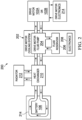
- FIG. 2 illustrates components of a drive motor cooling system and a battery heating system 200, both constructed and operating according to a disclosed embodiment.
- the drive motor cooling system and battery heating system 200 includes a drive motor cooling system 202 having a drive motor fluid pump 204, a fluid reservoir 206 and electronics 208.
- the fluid is oil, e.g., automatic transmission oil, lubricating oil, or similar oil. In other embodiments, other types of fluid may be used.
- the drive motor fluid pump 204 pumps fluid between the drive motor 102A and/or 102B, the fluid reservoir 206, and a heat exchanger 210.
- the heat exchanger 210 exchanges heat from the fluid with water or alcohol based coolant and routes the water or alcohol based coolant to a radiator 212 for cooling.
- the heat exchanger 210 may include another pump to circulate the water or alcohol based coolant to battery 106 via coolant tubes 214.
- the drive motor fluid pump 204 may couple directly to the coolant tubes 214 of the battery 106 and/or to the radiator 212 when a common fluid is used.
- the drive motor fluid pump 204 is controlled by electronics 208, which may include a digital computer, memory, and/or data processing and controlling components.
- the drive motor fluid pump 204 may include control valves to control flow of fluid between the drive motor 102A and/or 102B, the reservoir 206, and the heat exchanger 210 (and battery 106 coolant tubes 214 in other embodiments).
- the heat exchanger 210 may also include valves to direct the flow of coolant to the battery 106 coolant tubes 214 and to the radiator 212, under control of electronics 208 in some embodiments.
- the drive motor electronics 216 receive electrical power from the battery 106 and power the drive motor 102A and/or 102B.
- the drive motor electronics 216 include power electronics and control electronics.
- the power electronics may include an inverter to drive a stator of the drive motor 102A and/or 102B.
- the control electronics may include processing circuitry and memory.
- the processing circuitry may be a central processing unit, customized control circuitry, or other circuitry that is configured to execute software instructions and process data.
- the memory may include RAM, ROM, DRAM, static RAM, flash RAM, flash ROM, or another type of memory capable of storing software instructions and/or data.
- FIG. 3 illustrates components of a drive motor 102A (or 102B) and a portion of the components of a drive motor cooling system 200 according to a disclosed embodiment.
- the drive motor 102A includes a case 302, a stator 304 coupled to the case 302 that includes end-windings 305, stator drive electronics (not shown), at least one rotor bearing coupled to the case (not shown in FIG. 3 ), and a rotor 303 coupled to the case 302 via at least one rotor bearing.
- the rotor 303 includes a hollow cylindrical body 308 having an inner wall 310, an outer wall 312, a first distal end, and a second distal end.
- the rotor 303 also includes a first shaft portion 314 coupled to a first distal end of the hollow cylindrical body 308 and a second shaft portion 316 coupled to a second distal end of the hollow cylindrical body 308.
- the second shaft portion 316 includes a fluid feed tube 318 formed therewith having a fluid receive end 320 and a fluid feed end 322.
- the fluid feed end 322 extends to a central inner portion of the hollow cylindrical body 308.
- the fluid feed end 322 of the second shaft portion 316 includes a plurality of fluid spray ports 324 configured to spray fluid onto the inner wall 310 of the hollow cylindrical body 308.
- the rotor 303 also includes a plurality of fluid exit ports 326 formed adjacent the first distal end and second distal end of the hollow cylindrical body 308.
- a distance from the inner wall 310 of the hollow cylindrical body 308 to the plurality of fluid exit ports 326 is based upon a specified fluid thickness to support rotor cooling while the rotor 303 rotates, e.g., when the motor 102A is causing movement of a serviced vehicle 100.
- a specified fluid thickness is based upon viscosity of the fluid, rotational velocity of the rotor 303, and temperature of the fluid. The relationship between the inner wall 310, the plurality of fluid exit ports 326, and the specified fluid thickness will be described further with reference to FIGs. 4 and 5 .
- the rotor 303 also includes a cylindrical laminated stack 306 coupled to the outer wall 312 of the hollow cylindrical body 308.
- the cylindrical laminated stack 306 includes a plurality of permanent magnets and insulating material.
- the stator 304 includes a plurality of stator windings (not shown) that are intercoupled by the stator end-windings 305.
- the electric motor is a three phase 4-pole electric motor.
- the stator 304 includes three different phase windings in a 4-pole configuration and the cylindrical laminated stack 306 includes magnets placed to correspond to the three phase 4-pole configuration.
- the drive motor fluid pump 204 has a drive motor fluid pump output 307 and a drive motor fluid pump input 309.
- the drive motor cooling system 200 includes fluid circulation piping having an output portion coupled between the drive motor fluid pump output 307 and the fluid receive end 320 of the rotor second shaft portion 316. Further, the fluid circulation piping includes an input portion coupled between a fluid collection opening 311 in the case 302 and the drive motor fluid pump input 309.
- the drive motor fluid pump electronics 208 direct the drive motor fluid pump 204 (and associated valves) to pump fluid from the reservoir 206 into the fluid receive end 320 of the fluid feed tube 318. The fluid is recirculated to the drive motor fluid pump 204 via the fluid collection opening 311 in the case 302.
- the stator drive electronics and the drive motor fluid pump electronics are designed to operate in an inactive mode, a waste heat mode, and a rotor/stator cooling mode.
- the stator drive electronics provide electrical power to the stator 304 without causing rotation of the rotor 303.
- the drive motor fluid pump 204 at least substantially fills the hollow cylindrical body 308 with fluid. This waste heat mode operation causes the drive motor fluid pump 204 to circulate fluid on end-windings 305 of the stator 304 to heat the fluid.
- the waste heat generated from the end-windings 305 of the stator 304 is collected by the fluid and circulated to the heat exchanger 210.
- the heated fluid may then be routed to the coolant tubes 214 of the battery to heat the battery 106.
- the stator drive electronics provide electrical power to the stator 304 to cause rotation of the rotor 303 based upon the power requirements of the driving situation of the electric vehicle 100.
- the drive motor fluid pump 204 circulates fluid to manage the operating temperature of the rotor 303 and the stator 304 of the electric motor.
- the drive motor fluid pump 204 circulates the fluid to the heat exchanger 210.
- the heat exchanger 210 may cool the fluid or use heat from the fluid for battery 106 warming.
- FIG. 4 illustrates components of a drive motor 102A and a portion of the components of a drive motor cooling system according to a disclosed embodiment, particularly showing the manner in which fluid flows. Numbering between FIGs. 3 and 4 is consistent with arrows included in FIG. 4 to illustrate fluid flow and heat flow.
- fluid (oil in the embodiment of FIG. 4 ) enters the fluid feed tube 318 at the fluid receive end 320.
- the fluid feed tube 318 which may be a forged internal extension of the second shaft portion 316, transports the fluid towards the fluid feed end 322 of the second shaft portion 316.
- fluid exits the fluid feed tube 318 via fluid spray ports 324.
- the pressure of pumping of the fluid and centrifugal force when the rotor 303 is spinning causes the fluid to be received upon the inner wall 310 of the hollow cylindrical body 308.
- the oil builds up a 0.5mm thick layer (or other thickness in other embodiments) on a central portion of the inner wall 310 and runs along the inner wall 310 towards the fluid exit ports 326.
- the fluid exits the rotor 303 via the fluid exit ports 326 providing constant flow and heat transport.
- drive motor fluid pump 204 is not a regular coolant pump.
- the fluid that the drive motor fluid pump 204 pumps through the rotor 303 cannot be water/glycol fluid, which is not dielectric liquid, but is oil and, thus, the drive motor fluid pump 204 is an oil pump in embodiments described herein.
- the rotor cooling structure and method described herein may be used with any other stator cooling method.
- the rotor cooling described herein may be in series or in parallel with one or more stator cooling branches.
- FIGs. 5A and 5B illustrate a rotor 303 according to a representative embodiment, detailing the construct of fluid exit ports within a hollow central portion of the rotor 303. As shown, fluid exits the fluid exit ports 326 from the interior of the rotor 303. In the waste heat mode, the drive motor drive motor fluid pump fills the hollow cylindrical body 308 with fluid and the fluid is forced out of the fluid exit ports 326 by pumping pressure.
- the centrifugal force caused by the rotor's 303 rotation causes the fluid to form a film on the inner wall 310 of the hollow cylindrical body 308. Thickness of the film as it moves along the inner wall is based upon a distance from the outermost portion of the fluid exit ports 326 and the inner wall 310 as well as fluid properties such as viscosity and temperature, angular velocity of the rotor 303, and other factors. In one embodiment, this dimension is 0.5 mm.
- the fluid flows from a central portion of the inner wall 310 to distal portions of the hollow cylindrical body 308 in which the plurality of fluid exit ports 326 are formed.
- the fluid is at a first temperature when it exits the fluid spray ports 324 and is collected on the inner wall 310 at the central portion.
- the fluid flows along the inner wall 310 towards the distal ends of the hollow cylindrical body 308 it collects heat from the rotor 303 and the fluid is at a second temperature, which is higher than the first temperature.
- FIGs. 6A, 6B, 6C, and 6D illustrate operation of a drive motor according to one or more embodiments of the present disclosure.
- the rotor 303 includes at least one oil distribution ring 602 fixed to the rotor 303.
- the oil distribution ring 602 deflects fluid (oil) exiting the hollow cylindrical body 308 via the fluid exit ports 326 towards the stator end-windings 305. Deflection of the fluid is performed both during the waste heat mode and the rotor/stator cooling mode.
- FIG. 6A details the oil distribution ring 602 located on a proximal end of the rotor 303.
- FIG. 6B shows fluid flow (direction of arrow) from the inside of the hollow cylindrical body 308, out of fluid exit port 326, against the oil distribution ring 602, and towards the stator end-windings 305.
- FIG. 6C illustrates fluid flow from the oil distribution ring 602 towards the stator end-windings 305.
- FIG. 6D illustrates fluid flow from fluid exit port 326 past the laminated stack 306 towards the stator end-windings 305.
- FIG. 7 is a flow diagram illustrating electric motor cooling and battery heating operations 700 according to a disclosed embodiment.
- the electric motor cooling and battery heating operations include an inactive mode (step 702), a waste heat mode (step 704) and a rotor/stator cooling mode (step 718).
- the inactive mode (step 702) is used when the electric car is not being used, when the battery 106 is in an acceptable operating temperature range, and/or when the rotor/stator do not require cooling.
- the waste heat mode (step 704) is enacted when the thermal management of the battery 106 (or another component of the electric vehicle 100) requires warming of the battery 106. In cold locations, the temperature of the battery 106 may be as low as -30 degrees Fahrenheit due to ambient temperature. In order for the battery 106 to be sufficiently functional to drive the electrical vehicle 100, the temperature of the battery 106 must be raised to at least - 10 degrees Fahrenheit.
- the waste heat mode (step 704) serves this purpose.
- stator of the electric motor is powered to heat end-windings of the stator (and other portions of the stator 304 as well as the rotor 303) without causing the rotor 303 of the electric motor to rotate (step 706).
- Such stator 304 powering without rotor 303 rotation may be accomplished by applying DC voltage/current to the stator windings by the stator drive electronics. Alternately, stator 304 powering without rotor 303 rotation may be accomplished by applying the same AC drive signal to each of the phases of the stator windings.
- the drive motor fluid pump 204 is then operated to pump fluid into the hollow cylindrical body 308 of the rotor 303 (step 708). Such pumping continues until the hollow cylindrical body 308 is at least substantially filled.
- step 710 By continuing pumping until the hollow cylindrical body 308 is filled, fluid exits the hollow cylindrical body 308 via the fluid exit ports 326 and flows onto the stator end-windings 305 where the fluid gathers heat from the stator end-windings 305 (step 710).
- the oil distribution ring 602 may assist in directing the fluid onto the stator end-windings 305.
- the operation of step 710 may result in the case 302 of the electric motor being at least substantially filled with fluid.
- the heated fluid is then pumped to heat exchanger 210 to heat coolant circulating therethrough (step 712).
- the heated coolant is then circulated via the coolant tubes 214 to heat the battery 106 (step 714).
- the fluid heating and circulation operations are continued until the battery is heated to an acceptable operating temperature (as determined at step 716). Once the battery is heated to the acceptable operating temperature, operation returns to the inactive mode (step 702).
- the waste heat mode may commence with first warming the drive motor fluid pump 204 and fluid to an acceptable operating temperature.
- the drive motor fluid pump 204 is submerged in the fluid reservoir 206 and acts as a small heater for the fluid. In such case, the drive motor fluid pump 204 is operated very inefficiently to produce only heat and to produce little to no torque.
- the waste heat mode may continue to warm the battery 106. Local hot spots allow to drive motor fluid pump 204 to suck in fluid and around the drive motor fluid pump 204 into the downstream cooling and lubrication system by sucking cold oil in at the same time. This cold oil will be heated up subsequently, which will raise the fluid temperature even faster to continue with the waste heat mode.
- the waste heat mode operations 704 of FIG. 7 may be performed using differing rotor and stator structures than those described previously herein.
- a differing fluid feed tube structure may be used to feed the fluid into the hollow cylindrical body 308 of the rotor.
- the fluid feed tube may be separate from the shaft of the rotor.
- differing structure may be employed for the fluid to exit the hollow cylindrical body 308 of the rotor and/or to be directed onto the end-windings 305 of the stator.
- the stator In the rotor/stator cooling mode (step 718), the stator is enabled to rotate the rotor as required to propel the electric vehicle 100 (step 720). Fluid is pumped into the hollow cylindrical body 308 by the drive motor fluid pump 204 at a selected flow rate (step 722). The fluid flows along the inner wall 310 of the hollow cylindrical body 308 towards the distal ends of the hollow cylindrical body 308, collecting heat from the rotor 303 along the way, and then exits the hollow cylindrical body 308 via the fluid exit ports 326 towards the end-windings 305 of the stator (step 724). The fluid is then optionally routed to the heat exchanger 210 for cooling of the fluid (step 726).
- step 728 If a flow rate adjustment is necessary to alter the cooling rate (as determined at step 728), the fluid flow rate is modified (step 730). If not, operation returns to step 722.
- the rotor/stator cooling mode is ceased when the car ceases operations or if the rotor/stator no longer needs cooling.
- an electric motor comprising: a case; a stator that includes end-windings; and a rotor coupled to the case via rotor bearings, the rotor comprising: a hollow cylindrical body having an inner wall, an outer wall, a first distal end, and a second distal end; a first shaft portion coupled to the first distal end of the hollow cylindrical body; a second shaft portion coupled to the second distal end of the hollow cylindrical body; a fluid feed tube having a fluid receive end and a fluid feed end, the fluid feed end extending into the hollow cylindrical body; and a plurality of fluid exit ports; a drive motor fluid pump to pump fluid into the fluid receive end of the fluid feed tube; and drive motor electronics, wherein in a waste heat mode: the drive motor electronics power the stator without causing rotation of the rotor; the drive motor fluid pump at least partially fills the hollow cylindrical body with the fluid to force the fluid from the hollow cylindrical body to collect heat from the stator end-windings; and the drive motor
- the second shaft portion includes the fluid feed tube formed therein.
- the electric motor comprises a fluid circulation piping having: an output portion coupled between the drive motor fluid pump output and the fluid receive end of the second shaft portion; and an input portion coupled between a fluid collection point on the case and the drive motor fluid pump input.
- the electric motor comprises a radiator configured to cool the fluid.
- the electric motor comprises a heat exchanger coupled between the drive motor fluid pump and the radiator.
- the fluid feed end of the fluid feed tube comprises a plurality of fluid spray ports configured to spray fluid onto the inner wall of the hollow cylindrical body.
- the electric motor comprises an oil distribution ring coupled to the rotor and configured to deflect fluid from the plurality of fluid exit ports to the stator end-windings.
- an electric motor comprising: a case; a stator that includes end-windings; and a rotor coupled to the case via rotor bearings, the rotor comprising: a hollow cylindrical body, a first shaft portion, and a second shaft portion; a fluid feed tube having a fluid receive end and a fluid feed end, the fluid feed end extending into the hollow cylindrical body; and a plurality of fluid exit ports forming corresponding passages between an interior of the hollow cylindrical body and an exterior of the hollow cylindrical body; a drive motor fluid pump to pump fluid into the fluid receive end of the fluid feed tube; and drive motor electronics, wherein in a waste heat mode: the drive motor electronics power the stator without causing rotation of the rotor; the drive motor fluid pump circulates fluid into the hollow cylindrical body via the fluid feed tube, out of the plurality of fluid ports, and onto the stator end-windings to collect heat from the rotor and the stator; and the drive motor fluid pump circulates the fluid to a heat exchange
- the second shaft portion includes the fluid feed tube formed therein.
- the fluid feed tube is oriented along an axis of rotation of the rotor.
- the electric motor comprises fluid circulation piping having: an output portion coupled between the drive motor fluid pump output and the fluid receive end of the second shaft portion; and an input portion coupled between a fluid collection point on the case and the drive motor fluid pump input.
- electric motor comprises a radiator configured to cool the fluid.
- the electric motor comprises a heat exchanger coupled between the drive motor fluid pump and the radiator.
- the fluid feed end of the fluid feed tube comprises a plurality of fluid spray ports configured to spray fluid into the hollow cylindrical body.
- the electric motor comprises an oil distribution ring coupled to the rotor and configured to deflect fluid from the plurality of fluid exit ports to the stator end-windings.
- a method for operating an electric motor comprising: powering a stator of the electric motor to heat end-windings of the stator without causing a rotor of the electric motor to rotate; pumping fluid into a hollow cylindrical body of the rotor via a fluid feed tube, out of the hollow cylindrical body of the rotor via a plurality of fluid exit ports, and the end-windings of the stator to collect heat from at least the end-windings of the stator to produce heated fluid; and pumping the heated fluid to a heat exchanger for heating a battery.
- the fluid feed tube that is oriented along an axis of rotation of the rotor.
- the pumping the fluid into the hollow cylindrical body includes spraying the fluid from the fluid feed tube onto an inner wall of the hollow cylindrical body of the rotor.
- spraying the fluid from the fluid feed tube includes spraying the fluid onto a central portion of the inner wall of the hollow cylindrical body.
- the method comprises circulating coolant between the heat exchanger and the battery, wherein the coolant is heated by the heated fluid in the heat exchanger.
- Routines, methods, steps, operations, or portions thereof described herein may be implemented through electronics, e.g., one or more processors, using software and firmware instructions.
- a "processor” includes any hardware system, hardware mechanism or hardware component that processes data, signals or other information.
- a processor can include a system with a central processing unit, multiple processing units, dedicated circuitry for achieving functionality, or other systems.
- Some embodiments may be implemented by using software programming or code in one or more digital computers or processors, by using application specific integrated circuits (ASICs), programmable logic devices, field programmable gate arrays (FPGAs), optical, chemical, biological, quantum or nano-engineered systems, components and mechanisms.
- the terms “comprises,” “comprising,” “includes,” “including,” “has,” “having” or any contextual variants thereof, are intended to cover a non-exclusive inclusion.
- a process, product, article, or apparatus that comprises a list of elements is not necessarily limited to only those elements, but may include other elements not expressly listed or inherent to such process, product, article, or apparatus.
- “or” refers to an inclusive or and not to an exclusive or. For example, a condition "A or B" is satisfied by any one of the following: A is true (or present) and B is false (or not present), A is false (or not present) and B is true (or present), and both A and B is true (or present).
Landscapes
- Engineering & Computer Science (AREA)
- Power Engineering (AREA)
- Manufacturing & Machinery (AREA)
- Chemical & Material Sciences (AREA)
- Chemical Kinetics & Catalysis (AREA)
- Electrochemistry (AREA)
- General Chemical & Material Sciences (AREA)
- Motor Or Generator Cooling System (AREA)
- Motor Or Generator Frames (AREA)
- Electric Propulsion And Braking For Vehicles (AREA)
- Connection Of Motors, Electrical Generators, Mechanical Devices, And The Like (AREA)
Applications Claiming Priority (3)
| Application Number | Priority Date | Filing Date | Title |
|---|---|---|---|
| US201662346741P | 2016-06-07 | 2016-06-07 | |
| PCT/US2017/036290 WO2017214234A1 (fr) | 2016-06-07 | 2017-06-07 | Mode de chaleur résiduelle d'un moteur électrique pour chauffer une batterie |
| EP17733921.5A EP3465887B1 (fr) | 2016-06-07 | 2017-06-07 | Mode de chaleur résiduelle d'un moteur électrique pour chauffer une batterie |
Related Parent Applications (1)
| Application Number | Title | Priority Date | Filing Date |
|---|---|---|---|
| EP17733921.5A Division EP3465887B1 (fr) | 2016-06-07 | 2017-06-07 | Mode de chaleur résiduelle d'un moteur électrique pour chauffer une batterie |
Publications (2)
| Publication Number | Publication Date |
|---|---|
| EP4274006A2 true EP4274006A2 (fr) | 2023-11-08 |
| EP4274006A3 EP4274006A3 (fr) | 2024-01-10 |
Family
ID=59071121
Family Applications (4)
| Application Number | Title | Priority Date | Filing Date |
|---|---|---|---|
| EP17733921.5A Active EP3465887B1 (fr) | 2016-06-07 | 2017-06-07 | Mode de chaleur résiduelle d'un moteur électrique pour chauffer une batterie |
| EP23199627.3A Pending EP4274006A3 (fr) | 2016-06-07 | 2017-06-07 | Mode de chaleur perdue de moteur électrique pour chauffer une batterie |
| EP17731032.3A Active EP3465886B1 (fr) | 2016-06-07 | 2017-06-07 | Système de refroidissement de moteur électrique |
| EP17739366.7A Active EP3465889B1 (fr) | 2016-06-07 | 2017-06-07 | Protection contre les décharges de rotor d'un moteur électrique |
Family Applications Before (1)
| Application Number | Title | Priority Date | Filing Date |
|---|---|---|---|
| EP17733921.5A Active EP3465887B1 (fr) | 2016-06-07 | 2017-06-07 | Mode de chaleur résiduelle d'un moteur électrique pour chauffer une batterie |
Family Applications After (2)
| Application Number | Title | Priority Date | Filing Date |
|---|---|---|---|
| EP17731032.3A Active EP3465886B1 (fr) | 2016-06-07 | 2017-06-07 | Système de refroidissement de moteur électrique |
| EP17739366.7A Active EP3465889B1 (fr) | 2016-06-07 | 2017-06-07 | Protection contre les décharges de rotor d'un moteur électrique |
Country Status (8)
| Country | Link |
|---|---|
| US (5) | US10128705B2 (fr) |
| EP (4) | EP3465887B1 (fr) |
| JP (3) | JP6869265B2 (fr) |
| KR (3) | KR102155056B1 (fr) |
| CN (3) | CN109314443B (fr) |
| HU (3) | HUE060485T2 (fr) |
| PL (3) | PL3465889T3 (fr) |
| WO (3) | WO2017214232A1 (fr) |
Families Citing this family (109)
| Publication number | Priority date | Publication date | Assignee | Title |
|---|---|---|---|---|
| KR20180134348A (ko) * | 2016-04-12 | 2018-12-18 | 티엠4 인코포레이티드 | 밀봉된 고정자를 가진 액체 냉각 전기 머신 |
| PL3465889T3 (pl) | 2016-06-07 | 2021-10-25 | Tesla, Inc. | Zabezpieczenie przed wyładowaniem rotora silnika elektrycznego |
| FR3056356B1 (fr) * | 2016-09-21 | 2019-07-26 | Institut Vedecom | Manchon et arbre de machine electrique |
| US10967702B2 (en) | 2017-09-07 | 2021-04-06 | Tesla, Inc. | Optimal source electric vehicle heat pump with extreme temperature heating capability and efficient thermal preconditioning |
| CN119928540A (zh) | 2018-09-27 | 2025-05-06 | 艾里逊变速箱公司 | 电动轮轴组件 |
| DE112019004906T5 (de) * | 2018-09-27 | 2021-06-17 | Allison Transmission, Inc. | Elektromotor für eine Achsbaugruppe |
| US11005337B2 (en) | 2018-10-23 | 2021-05-11 | Atieva, Inc. | Removable differential for an active core electric motor |
| US10797562B2 (en) * | 2018-10-23 | 2020-10-06 | Atieva, Inc. | High torque and power density drive system with shortened overall width |
| DE102018221569A1 (de) | 2018-12-12 | 2020-06-18 | Thyssenkrupp Ag | Rotoreinrichtung für eine elektrische Maschine, sowie elektrische Maschine |
| DE102018009832A1 (de) | 2018-12-14 | 2019-06-27 | Daimler Ag | Hohlwelle für einen Rotor einer elektrischen Maschine |
| TWI706624B (zh) * | 2019-03-20 | 2020-10-01 | 東元電機股份有限公司 | 馬達循環冷卻系統及其油冷馬達結構 |
| CN109921555A (zh) * | 2019-03-29 | 2019-06-21 | 重庆升科精锻科技有限公司 | 一种焊接式新能源汽车电机轴 |
| CN109904976B (zh) * | 2019-03-29 | 2021-01-26 | 重庆升科精锻科技有限公司 | 一种两段式新能源汽车电机轴 |
| DE102019117637A1 (de) * | 2019-07-01 | 2021-01-07 | Dr. Ing. H.C. F. Porsche Aktiengesellschaft | Anordnung zum Kühlen einer Elektromaschine bei einem Kraftfahrzeug sowie Verfahren zum Betreiben der Anordnung |
| CN110492640A (zh) * | 2019-07-03 | 2019-11-22 | 南京越博动力系统股份有限公司 | 电机的转子以及电机 |
| CN110729856A (zh) * | 2019-09-03 | 2020-01-24 | 精进电动科技股份有限公司 | 一种油水双冷的电驱动总成和新能源汽车 |
| US11387712B2 (en) * | 2019-09-13 | 2022-07-12 | GM Global Technology Operations LLC | Method to reduce oil shear drag in airgap |
| DE102019214082A1 (de) * | 2019-09-16 | 2021-03-18 | Vitesco Technologies GmbH | Thermomanagementsystem und Fahrzeug |
| DE102019214080A1 (de) | 2019-09-16 | 2021-03-18 | Vitesco Technologies GmbH | Verfahren zur Überwachung eines mittels einer Ölpumpe erzeugten Ölflusses in einem Ölkühlkreis eines Thermomanagementsystems |
| DE102019214079A1 (de) * | 2019-09-16 | 2021-03-18 | Vitesco Technologies GmbH | Thermomanagementsystem und Fahrzeug |
| JPWO2021065240A1 (fr) * | 2019-09-30 | 2021-04-08 | ||
| KR102275325B1 (ko) * | 2019-11-06 | 2021-07-09 | 송과모터스 주식회사 | 구동모터의 냉각기능 향상을 위한 회전자 구조 |
| KR102238301B1 (ko) * | 2019-11-06 | 2021-04-09 | 송과모터스 주식회사 | 구동모터의 회전자 냉각 구조 |
| KR102314718B1 (ko) * | 2019-11-07 | 2021-10-18 | 현대트랜시스 주식회사 | 베어링 전식 방지장치 |
| DE102019130868A1 (de) * | 2019-11-15 | 2021-05-20 | Ford Global Technologies, Llc | Elektrofahrzeug und Invertervorrichtung mit Heizfunktion |
| DE102019218531A1 (de) * | 2019-11-29 | 2021-06-02 | Zf Friedrichshafen Ag | Antriebseinheit, umfassend eine elektrische Maschine und ein Getriebe |
| DE102019133877A1 (de) * | 2019-12-11 | 2021-06-17 | Schaeffler Technologies AG & Co. KG | Elektrische Antriebsanordnung mit einer Ableitvorrichtung mit integrierter Abriebschutzeinrichtung |
| US12241507B2 (en) * | 2019-12-11 | 2025-03-04 | Schaeffler Technologies AG & Co. KG | Discharge device for discharging an electrical charge from a rotor of an electric motor |
| DE102019133889A1 (de) * | 2019-12-11 | 2021-06-17 | Schaeffler Technologies AG & Co. KG | Elektrische Maschine mit einer Ableitvorrichtung |
| DE102019133875A1 (de) * | 2019-12-11 | 2021-06-17 | Schaeffler Technologies AG & Co. KG | Ableitvorrichtung mit integrierter Hülse zur Überbrückung eines radialen Abstands sowie elektrische Antriebsanordnung mit der Ableitvorrichtung |
| DE102020102885A1 (de) * | 2019-12-18 | 2021-06-24 | Schaeffler Technologies AG & Co. KG | Elektrifizierter Antriebsstrang mit Wärmetauscher-Anordnung in Kühlkreis sowie Elektrofahrzeug mit Antriebsstrang |
| DE102020102884A1 (de) * | 2019-12-18 | 2021-06-24 | Schaeffler Technologies AG & Co. KG | Elektrifizierter Antriebsstrang mit Wärmetauscher-Anordnung in Wärmeabführkreis sowie Elektrofahrzeug mit Antriebsstrang |
| CN111030383A (zh) * | 2019-12-24 | 2020-04-17 | 中国科学院声学研究所 | 一种用于低温环境中的自泵式喷油内循环散热电机 |
| ES2966524T3 (es) * | 2020-01-15 | 2024-04-22 | Novelis Inc | Sistema de rotor con rotor magnético enfriado internamente para calentar un sustrato |
| GB202001012D0 (en) | 2020-01-24 | 2020-03-11 | Ocado Innovation Ltd | Raising and lowering containers |
| DE102020102078A1 (de) * | 2020-01-29 | 2020-12-31 | Schaeffler Technologies AG & Co. KG | Elektrische Antriebsanordnung mit einer Ableiteinrichtung mit isolierter Lagereinrichtung |
| CN111403843B (zh) | 2020-02-18 | 2021-10-01 | 华为技术有限公司 | 一种车辆热管理系统和方法 |
| US11431227B2 (en) | 2020-03-03 | 2022-08-30 | Dana Belgium N.V. | Systems and methods for providing direct spray cooling in an electric motor |
| DE102020108834A1 (de) | 2020-03-31 | 2021-09-30 | Schaeffler Technologies AG & Co. KG | Elektrische Antriebsanordnung für ein Fahrzeug |
| CN112670620A (zh) * | 2020-04-03 | 2021-04-16 | 长城汽车股份有限公司 | 车辆及其电池包的加热方法、装置 |
| CN112744124B (zh) | 2020-04-22 | 2022-03-22 | 长城汽车股份有限公司 | 电池包加热的控制方法、装置及整车控制器 |
| DE102020206743A1 (de) * | 2020-05-29 | 2021-12-02 | Zf Friedrichshafen Ag | Antriebseinheit für ein elektrisch angetriebenes Fahrzeug |
| CN116670458A (zh) * | 2020-06-05 | 2023-08-29 | 朴范用 | 热交换器及包括其的能量转换装置组件 |
| CN114402514B (zh) | 2020-07-31 | 2023-07-14 | 宁德时代新能源科技股份有限公司 | 电机、控制方法、动力系统以及电动汽车 |
| DE102020121663A1 (de) * | 2020-08-18 | 2022-02-24 | Nidec Motors & Actuators (Germany) Gmbh | Motorwellenanordnung mit Motorwelle und Zulaufrohr |
| JP7563685B2 (ja) * | 2020-10-23 | 2024-10-08 | ファーウェイ デジタル パワー テクノロジーズ カンパニー リミテッド | モーター、モーター・コントローラ、熱交換システム、及び制御方法 |
| CN112277901B (zh) * | 2020-10-30 | 2022-07-12 | 北京理工大学 | 用于收集汽车制动能量的摩擦电能收集系统 |
| DE102020214702A1 (de) | 2020-11-23 | 2022-05-25 | Volkswagen Aktiengesellschaft | Hohlwelle für Kraftfahrzeuge mit zumindest zwei axial zueinander beabstandeten Auslassöffnungen |
| CN112701824B (zh) | 2020-12-25 | 2022-06-14 | 华为数字能源技术有限公司 | 电机转子、电机及车辆 |
| CN112769268A (zh) * | 2020-12-30 | 2021-05-07 | 华为技术有限公司 | 动力传递组件及动力总成 |
| US12049925B2 (en) | 2020-12-30 | 2024-07-30 | Dana Heavy Vehicle Systems Group, Llc | Systems and method for an electric motor with spray ring |
| US11770041B2 (en) | 2020-12-30 | 2023-09-26 | Dana Heavy Vehicle Systems Group, Llc | Systems and method for an electric motor with molded coolant jacket and spray ring |
| US11916459B2 (en) | 2020-12-30 | 2024-02-27 | Dana Heavy Vehicle Systems Group, Llc | Systems and method for an electric motor with spray ring |
| CN114801892B (zh) * | 2021-01-28 | 2025-12-19 | 蔚然(南京)动力科技有限公司 | 电机系统的控制方法、电机控制装置及电机系统 |
| CN114514694B (zh) * | 2021-01-29 | 2024-04-09 | 华为数字能源技术有限公司 | 一种电机控制器、动力总成、控制方法及电动车辆 |
| US11824425B2 (en) | 2021-02-04 | 2023-11-21 | Volvo Car Corporation | Electric machine |
| DE102022104048A1 (de) | 2021-02-25 | 2022-08-25 | Nidec Corporation | Motor |
| WO2022178868A1 (fr) * | 2021-02-26 | 2022-09-01 | 华为数字能源技术有限公司 | Groupe motopropulseur et véhicule électrique |
| CN116897456A (zh) * | 2021-03-03 | 2023-10-17 | 华为数字能源技术有限公司 | 异步电机处理方法、装置、设备、系统以及交通工具 |
| WO2022191952A1 (fr) | 2021-03-11 | 2022-09-15 | American Axle & Manufacturing, Inc. | Unité de propulsion électrique équipée d'un échangeur formé par des disques dotés d'une partie ressort de disque et logés dans un alésage d'un arbre de rotor d'un moteur électrique |
| DE102021106692B4 (de) | 2021-03-18 | 2025-07-17 | Schaeffler Technologies AG & Co. KG | Einsatz einer Umschlingungskupplung für Momentübertragung zwischen E-Maschinen in einem Hybridgetriebe |
| US11735982B2 (en) | 2021-03-18 | 2023-08-22 | General Electric Company | Bearing current mitigation for an electric machine embedded in a gas turbine engine |
| US11932078B2 (en) | 2021-03-31 | 2024-03-19 | Tesla, Inc. | Electric vehicle heat pump using enhanced valve unit |
| CN114301241B (zh) | 2021-03-31 | 2024-06-11 | 华为数字能源技术有限公司 | 电机、动力总成及电机驱动设备 |
| US12027922B2 (en) * | 2021-04-20 | 2024-07-02 | Rivian Ip Holdings, Llc | Rotor assembly and method for motor end winding cooling and bearing lubrication |
| DE102021205261A1 (de) | 2021-05-21 | 2022-11-24 | Volkswagen Aktiengesellschaft | Rotorwellensystem für eine elektrische Maschine |
| CN114337422B (zh) | 2021-06-01 | 2024-10-11 | 华为数字能源技术有限公司 | 一种控制电机加热的方法及多电机驱动系统的控制方法 |
| JP7665447B2 (ja) * | 2021-06-30 | 2025-04-21 | ニデック株式会社 | 駆動装置、車両 |
| JP7665448B2 (ja) | 2021-06-30 | 2025-04-21 | ニデック株式会社 | モータ、駆動装置 |
| JP7682719B2 (ja) * | 2021-06-30 | 2025-05-26 | ニデック株式会社 | 駆動装置、車両 |
| DE102021214391A1 (de) | 2021-08-05 | 2023-02-09 | Aktiebolaget Skf | Lageranordnung für einen Elektromotor, und Elektromotor |
| CN113472112B (zh) * | 2021-08-05 | 2023-01-06 | 威海西立电子股份有限公司 | 一种转子冷却方法及系统 |
| CN113746275A (zh) * | 2021-08-31 | 2021-12-03 | 株洲齿轮有限责任公司 | 电机放电结构和轴电流导流效果检测方法 |
| DE102022209373A1 (de) | 2021-09-10 | 2023-03-16 | Nidec Corporation | Antriebsvorrichtung und fahrzeug |
| JP2023048350A (ja) | 2021-09-28 | 2023-04-07 | 日本電産株式会社 | モータ、駆動装置 |
| CN113928129B (zh) * | 2021-09-30 | 2024-07-30 | 华为数字能源技术有限公司 | 汽车的驱动电机的控制方法和相关设备、以及变速器 |
| CN116073562A (zh) * | 2021-10-29 | 2023-05-05 | 株洲中车时代电气股份有限公司 | 防轴承电腐蚀的轴端结构及电机 |
| DE102021213384A1 (de) * | 2021-11-29 | 2023-06-01 | Zf Friedrichshafen Ag | Anordnung zur Erdung einer Welle |
| DE102021213388A1 (de) | 2021-11-29 | 2023-06-01 | Zf Friedrichshafen Ag | Anordnung zur Erdung einer Welle |
| DE102022200444A1 (de) | 2022-01-17 | 2023-07-20 | Aktiebolaget Skf | Wartbare Lageranordnung |
| US12113423B2 (en) | 2022-02-14 | 2024-10-08 | Dana Motion Systems Italia S.R.L. | Electric motor with integrated pump |
| DE102022107954A1 (de) | 2022-04-04 | 2023-10-05 | Dr. Ing. H.C. F. Porsche Aktiengesellschaft | Antriebsstrang zum Antrieb eines Kraftfahrzeugs und Verfahren zum Betrieb eines derartigen Antriebsstrangs |
| DE102022109039A1 (de) | 2022-04-13 | 2023-10-19 | Bayerische Motoren Werke Aktiengesellschaft | Kühlfluidführende Rotorwelle für einen Rotor einer elektrischen Maschine mit Prallwand |
| DE102022109887A1 (de) | 2022-04-25 | 2023-10-26 | Bayerische Motoren Werke Aktiengesellschaft | Kühlfluidführende Rotorwelle für einen Rotor einer elektrischen Maschine mit Prallfläche |
| DE102022204631A1 (de) | 2022-05-11 | 2023-11-16 | Volkswagen Aktiengesellschaft | Wärmebereitstellung bei einem stehenden Elektrofahrzeug |
| US12215482B2 (en) | 2022-05-12 | 2025-02-04 | Dana Italia S.R.L. | Implements electronic power limitation |
| US12427868B2 (en) | 2022-05-17 | 2025-09-30 | Ford Global Technologies, Llc | Methods and system for controlling loss mode for an electric machine |
| US12374953B2 (en) * | 2022-06-14 | 2025-07-29 | Hyundai Mobis Co., Ltd. | Anti-erosion structure of motor including a ground structure |
| US12366267B2 (en) * | 2022-09-19 | 2025-07-22 | GM Global Technology Operations LLC | Rotor grounding system with sacrificial bearing |
| JP7848665B2 (ja) | 2022-11-14 | 2026-04-21 | トヨタ自動車株式会社 | 電気モータ |
| US12397630B2 (en) * | 2022-11-15 | 2025-08-26 | GM Global Technology Operations LLC | Electric drive unit magnetohydrodynamic cooling |
| US20240235328A1 (en) * | 2023-01-09 | 2024-07-11 | GM Global Technology Operations LLC | Cooling for electric motors |
| US12323014B2 (en) * | 2023-01-11 | 2025-06-03 | GM Global Technology Operations LLC | Managing bearing currents in an electric machine |
| DE102023200317A1 (de) * | 2023-01-17 | 2024-07-18 | Volkswagen Aktiengesellschaft | Elektrische Maschine mit Potentialausgleichsvorrichtung |
| US12231752B2 (en) | 2023-01-19 | 2025-02-18 | Comcast Cable Communications, Llc | Device temperature control using device components |
| US12447864B2 (en) | 2023-02-02 | 2025-10-21 | Ford Global Technologies, Llc | Electrified vehicle with wound rotor synchronous electric machine controlled to heat battery |
| DE102023104925A1 (de) | 2023-02-28 | 2024-08-29 | Schaeffler Technologies AG & Co. KG | Verfahren zur Batterieerwärmung und Fluidvorrichtung |
| DE102023104904A1 (de) | 2023-02-28 | 2024-08-29 | Schaeffler Technologies AG & Co. KG | Verfahren zur Verlustwärmeerzeugung, Verfahren zur Batterieerwärmung und Antriebsstrangvorrichtung |
| DE102023202328A1 (de) * | 2023-03-15 | 2024-09-19 | Zf Friedrichshafen Ag | Vorrichtung und Verfahren zur Wellenerdung |
| US12316205B2 (en) | 2023-03-20 | 2025-05-27 | Fca Us Llc | Rotor overhang design for direct oil cooling of electric machines |
| US12218327B2 (en) | 2023-03-27 | 2025-02-04 | Ford Global Technologies, Llc | Battery heating via heat collected from coolant passing through hollow windings of electric machine |
| DE102023115500B4 (de) * | 2023-06-14 | 2025-03-27 | Schaeffler Technologies AG & Co. KG | Rotoranordnung, elektrische Maschine, Verfahren zur Steuerung einer Rotoranordnung, Computerprogrammprodukt und Steuereinheit |
| DE102023207587A1 (de) * | 2023-08-08 | 2025-02-13 | Mahle International Gmbh | Rotorbaugruppe für eine elektrische Maschine und elektrische Maschine |
| DE102024104081A1 (de) | 2024-02-14 | 2025-08-14 | Schaeffler Technologies AG & Co. KG | Verfahren zum Betrieb eines Elektromotors |
| CN117927439B (zh) * | 2024-03-18 | 2024-08-16 | 潍柴动力股份有限公司 | 一种一体式电动泵及车辆 |
| DE102024108522B4 (de) | 2024-03-26 | 2026-03-26 | Schaeffler Technologies AG & Co. KG | Verfahren zur feldorientierten Steuerung/Regelung einer Synchronmaschine, Steuereinheit und elektrischer Antriebsstrang |
| DE102024205778A1 (de) | 2024-06-21 | 2025-12-24 | Robert Bosch Gesellschaft mit beschränkter Haftung | Antriebsanordnung, Verfahren zum Betreiben einer Antriebsanordnung und ein Fahrzeug |
| DE102024123139A1 (de) | 2024-08-13 | 2026-02-19 | Schaeffler Technologies AG & Co. KG | System zur gezielten Verlusterzeugung in einem Elektromotor im gesamten Betriebsbereich des Elektromotors, Elektromotor, Kraftfahrzeugantrieb und Verfahren zum Betreiben eines elektromotorischen Kraftfahrzeugantriebes |
| WO2025041113A1 (fr) * | 2024-09-12 | 2025-02-27 | Arabamery Mosoud | Système de refroidissement isolé air-air avancé et procédé pour moteurs électriques industriels à haute vitesse, haute tension et haute densité de puissance |
Citations (3)
| Publication number | Priority date | Publication date | Assignee | Title |
|---|---|---|---|---|
| US6191511B1 (en) | 1998-09-28 | 2001-02-20 | The Swatch Group Management Services Ag | Liquid cooled asynchronous electric machine |
| US6329731B1 (en) | 1999-08-10 | 2001-12-11 | The Swatch Group Management Services Ag | Driving unit including a liquid cooled electric motor and a planetary gear |
| US7156195B2 (en) | 2002-10-23 | 2007-01-02 | Nissan Motor Co., Ltd. | Cooling system for electric motor of vehicle |
Family Cites Families (59)
| Publication number | Priority date | Publication date | Assignee | Title |
|---|---|---|---|---|
| US3629628A (en) | 1970-07-06 | 1971-12-21 | Gen Motors Corp | Cooling arrangement for a squirrel cage rotor assembly |
| JPS601298Y2 (ja) * | 1980-01-31 | 1985-01-16 | 三菱電機株式会社 | 回転軸支持装置 |
| JPS6188467A (ja) | 1984-09-12 | 1986-05-06 | Seiko Epson Corp | 充電式電気かみそりの電源装置 |
| JPS6188467U (fr) * | 1984-11-16 | 1986-06-09 | ||
| JPH0233569U (fr) * | 1988-08-22 | 1990-03-02 | ||
| DE4333613C2 (de) * | 1992-10-01 | 2002-10-17 | Hitachi Ltd | Kühlsystem eines elektrischen Kraftfahrzeugs und eines dafür benutzten Elektromotors |
| JPH10285876A (ja) * | 1997-03-28 | 1998-10-23 | Toyo Electric Mfg Co Ltd | 羽根車付き液冷式回転電動機 |
| JP3886697B2 (ja) * | 1999-04-27 | 2007-02-28 | アイシン・エィ・ダブリュ株式会社 | 駆動装置 |
| JP3608430B2 (ja) * | 1999-04-28 | 2005-01-12 | 三菱電機株式会社 | 回転電機 |
| US6608422B2 (en) * | 1999-05-06 | 2003-08-19 | Prestolite Electric, Inc. | Alternator with an electric contact bearing assembly |
| WO2000071903A1 (fr) * | 1999-05-21 | 2000-11-30 | Sumitomo Electric Industries, Ltd. | Structure de palier, moteur d'entrainement, et unite de disque dur |
| JP2001197705A (ja) * | 2000-01-12 | 2001-07-19 | Meidensha Corp | 回転電機の回転子用冷却装置 |
| US6394207B1 (en) | 2000-02-16 | 2002-05-28 | General Motors Corporation | Thermal management of fuel cell powered vehicles |
| US6670733B2 (en) * | 2001-09-27 | 2003-12-30 | Reliance Electric Technologies, Llc | System and method of reducing bearing voltage |
| US7193836B2 (en) * | 2003-03-17 | 2007-03-20 | Illinois Tool Works Inc | Grounding brush for mitigating electrical current on motor shafts |
| JP3979389B2 (ja) * | 2004-01-09 | 2007-09-19 | 日産自動車株式会社 | 電動機のロータ冷却構造 |
| JP4447410B2 (ja) * | 2004-09-03 | 2010-04-07 | 本田技研工業株式会社 | 電動車両用モータのロータ冷却装置 |
| CA2659598A1 (fr) | 2006-08-08 | 2008-02-14 | Kyorin Pharmaceutical Co., Ltd. | Derive d'ester de l'acide aminophosphorique et modulateur durecepteur s1p contenant ledit derive en tant que principe actif |
| JP4665911B2 (ja) * | 2007-02-07 | 2011-04-06 | トヨタ自動車株式会社 | 冷却システム |
| US7789176B2 (en) | 2007-04-11 | 2010-09-07 | Tesla Motors, Inc. | Electric vehicle thermal management system |
| JP4958637B2 (ja) * | 2007-05-26 | 2012-06-20 | 三洋電機株式会社 | ハイブリッドカー |
| JP2007300800A (ja) * | 2007-08-24 | 2007-11-15 | Matsushita Electric Ind Co Ltd | 直流整流子電動機 |
| US8421286B2 (en) * | 2008-07-03 | 2013-04-16 | Nidec Motor Corporation | Kit and method for attaching a grounding ring to an electrical motor |
| US8183727B2 (en) * | 2008-11-24 | 2012-05-22 | Caterpillar Inc. | Grounding mechanism for electric motor |
| JP2010172132A (ja) * | 2009-01-23 | 2010-08-05 | Nippon Steel Corp | 回転電機及び回転電機の冷却方法 |
| US8138642B2 (en) * | 2009-06-17 | 2012-03-20 | Hamilton Sundstrand Corporation | Oil cooled generator |
| JP2011097784A (ja) * | 2009-10-30 | 2011-05-12 | Aisin Aw Co Ltd | 回転電機用ロータ |
| DE102009051651B4 (de) * | 2009-11-02 | 2012-01-26 | Siemens Aktiengesellschaft | Windkraftgenerator mit Innenkühlkreislauf |
| JP5331722B2 (ja) * | 2010-02-05 | 2013-10-30 | 株式会社日立製作所 | 車両の電気駆動システム |
| US20130038182A1 (en) * | 2010-03-17 | 2013-02-14 | Hitachi, Ltd. | Inverter-driven dynamo electric machine and system, bearing, and end bracket for same |
| JP5409462B2 (ja) * | 2010-03-19 | 2014-02-05 | トヨタ自動車株式会社 | 電動機 |
| US9154006B2 (en) * | 2010-03-24 | 2015-10-06 | Aisin Aw Co., Ltd. | Rotor for rotating electric machine |
| DE102010022320A1 (de) * | 2010-06-01 | 2011-12-01 | Schaeffler Technologies Gmbh & Co. Kg | Elektrischer Radantrieb |
| US8336319B2 (en) | 2010-06-04 | 2012-12-25 | Tesla Motors, Inc. | Thermal management system with dual mode coolant loops |
| WO2011163226A2 (fr) * | 2010-06-21 | 2011-12-29 | Nidec Motor Corporation | Ensembles moteurs électriques comprenant un refroidissement de stator et/ou de rotor |
| WO2012026044A1 (fr) * | 2010-08-27 | 2012-03-01 | トヨタ自動車株式会社 | Dispositif de commande pour véhicules |
| US8970074B2 (en) * | 2010-11-01 | 2015-03-03 | Mission Motor Company | Electric motor and method of cooling |
| US9030063B2 (en) * | 2010-12-17 | 2015-05-12 | Tesla Motors, Inc. | Thermal management system for use with an integrated motor assembly |
| JP5734765B2 (ja) * | 2011-06-24 | 2015-06-17 | トヨタ自動車株式会社 | 回転電機の冷却構造 |
| US8970147B2 (en) * | 2011-06-29 | 2015-03-03 | Tesla Motors, Inc. | Traction motor controller with dissipation mode |
| JP5776406B2 (ja) * | 2011-07-25 | 2015-09-09 | 日産自動車株式会社 | 燃料電池システム |
| JP2013038998A (ja) * | 2011-08-10 | 2013-02-21 | Toyota Industries Corp | 二次電池搭載車両 |
| WO2013136405A1 (fr) * | 2012-03-12 | 2013-09-19 | トヨタ自動車株式会社 | Machine électrique rotative |
| US8896167B2 (en) * | 2012-05-25 | 2014-11-25 | Deere & Company | Electric machine rotor cooling method |
| US8970075B2 (en) | 2012-08-08 | 2015-03-03 | Ac Propulsion, Inc. | Liquid cooled electric motor |
| JP2014082841A (ja) * | 2012-10-15 | 2014-05-08 | Toyota Motor Corp | 電動機 |
| GB2509308B (en) * | 2012-12-18 | 2015-06-10 | Protean Electric Ltd | A heating system for a vehicle battery |
| US9306433B2 (en) * | 2013-03-13 | 2016-04-05 | E-Aam Driveline Systems Ab | Drive module with spray cooling of electric motor |
| JP6073763B2 (ja) * | 2013-08-30 | 2017-02-01 | 株式会社日立産機システム | アキシャルギャップ型永久磁石同期電動機 |
| DE102013219186B4 (de) * | 2013-09-24 | 2022-11-24 | Vitesco Technologies GmbH | Elektrische Maschine und Verbindungseinheit für elektrische Maschine. |
| DE102013020332A1 (de) * | 2013-12-04 | 2014-07-31 | Daimler Ag | Elektrische Maschine, insbesondere Asynchronmaschine |
| US20160023532A1 (en) * | 2014-07-25 | 2016-01-28 | Atieva, Inc. | EV Integrated Temperature Control System |
| JP5911033B1 (ja) * | 2014-10-02 | 2016-04-27 | 三菱電機株式会社 | 回転電機の運転方法 |
| US10514191B2 (en) | 2015-01-15 | 2019-12-24 | Ford Global Technologies, Llc | De-icing control in a vapor compression heat pump system |
| CN204906069U (zh) * | 2015-08-20 | 2015-12-23 | 无锡法拉第电机有限公司 | 发电机轴承防静电腐蚀装置及其发电机 |
| PL3465889T3 (pl) | 2016-06-07 | 2021-10-25 | Tesla, Inc. | Zabezpieczenie przed wyładowaniem rotora silnika elektrycznego |
| EP3419843B1 (fr) | 2016-09-02 | 2022-11-16 | Apple Inc. | Système de gestion thermique de véhicule et échangeurs de chaleur |
| JP2018087629A (ja) * | 2016-11-30 | 2018-06-07 | 株式会社ジェイテクト | 転がり軸受装置 |
| US10967702B2 (en) | 2017-09-07 | 2021-04-06 | Tesla, Inc. | Optimal source electric vehicle heat pump with extreme temperature heating capability and efficient thermal preconditioning |
-
2017
- 2017-06-07 PL PL17739366T patent/PL3465889T3/pl unknown
- 2017-06-07 KR KR1020197000256A patent/KR102155056B1/ko active Active
- 2017-06-07 JP JP2018563038A patent/JP6869265B2/ja active Active
- 2017-06-07 EP EP17733921.5A patent/EP3465887B1/fr active Active
- 2017-06-07 EP EP23199627.3A patent/EP4274006A3/fr active Pending
- 2017-06-07 HU HUE17731032A patent/HUE060485T2/hu unknown
- 2017-06-07 EP EP17731032.3A patent/EP3465886B1/fr active Active
- 2017-06-07 HU HUE17739366A patent/HUE053732T2/hu unknown
- 2017-06-07 JP JP2018563058A patent/JP6885971B2/ja active Active
- 2017-06-07 WO PCT/US2017/036285 patent/WO2017214232A1/fr not_active Ceased
- 2017-06-07 PL PL17733921.5T patent/PL3465887T3/pl unknown
- 2017-06-07 PL PL17731032.3T patent/PL3465886T3/pl unknown
- 2017-06-07 KR KR1020197000181A patent/KR102215720B1/ko active Active
- 2017-06-07 CN CN201780035335.9A patent/CN109314443B/zh active Active
- 2017-06-07 WO PCT/US2017/036300 patent/WO2017214239A1/fr not_active Ceased
- 2017-06-07 CN CN201780035391.2A patent/CN109314444B/zh active Active
- 2017-06-07 HU HUE17733921A patent/HUE063837T2/hu unknown
- 2017-06-07 CN CN201780035352.2A patent/CN109314445B/zh active Active
- 2017-06-07 WO PCT/US2017/036290 patent/WO2017214234A1/fr not_active Ceased
- 2017-06-07 EP EP17739366.7A patent/EP3465889B1/fr active Active
- 2017-06-07 JP JP2018563059A patent/JP7012031B2/ja active Active
- 2017-06-07 KR KR1020197000473A patent/KR102222407B1/ko active Active
- 2017-11-30 US US15/827,435 patent/US10128705B2/en active Active
- 2017-11-30 US US15/827,506 patent/US10587162B2/en not_active Expired - Fee Related
- 2017-11-30 US US15/827,363 patent/US11088582B2/en not_active Expired - Fee Related
-
2020
- 2020-03-09 US US16/813,416 patent/US11218045B2/en active Active
-
2021
- 2021-08-05 US US17/444,507 patent/US11757320B2/en active Active
Patent Citations (3)
| Publication number | Priority date | Publication date | Assignee | Title |
|---|---|---|---|---|
| US6191511B1 (en) | 1998-09-28 | 2001-02-20 | The Swatch Group Management Services Ag | Liquid cooled asynchronous electric machine |
| US6329731B1 (en) | 1999-08-10 | 2001-12-11 | The Swatch Group Management Services Ag | Driving unit including a liquid cooled electric motor and a planetary gear |
| US7156195B2 (en) | 2002-10-23 | 2007-01-02 | Nissan Motor Co., Ltd. | Cooling system for electric motor of vehicle |
Also Published As
Similar Documents
| Publication | Publication Date | Title |
|---|---|---|
| US11218045B2 (en) | Electric motor waste heat mode to heat battery | |
| CN109997296B (zh) | 用于冷却电机的方法以及使用这种方法的电机 | |
| US7579725B2 (en) | Liquid cooled rotor assembly | |
| US20070216236A1 (en) | Method and apparatus for heat removal from electric motor winding end-turns | |
| US20160169231A1 (en) | Integrated motor and fluid pump | |
| KR20000023369A (ko) | 수냉식의 비동기 발전기 | |
| US10309518B2 (en) | Gear unit and a method for heating lubricant oil of a gear unit | |
| CN115244832A (zh) | 具有集成冷却系统的电动机 | |
| HK40003354A (en) | Electric motor waste heat mode to heat battery | |
| HK40003354B (en) | Electric motor waste heat mode to heat battery | |
| HK40003352A (en) | Electric motor cooling system | |
| HK40003352B (zh) | 电动机冷却系统 | |
| CN112671173B (zh) | 用于无人艇内转子无刷电机的循环冷却系统和方法 | |
| EP4679683A1 (fr) | Système de refroidissement pour un appareil électrique et moteur électrique doté du système de refroidissement | |
| WO2012024475A2 (fr) | Matrice de matériau destinée à améliorer un milieu de refroidissement | |
| HK1213968B (en) | A gear unit and a method for heating lubricant oil of a gear unit |
Legal Events
| Date | Code | Title | Description |
|---|---|---|---|
| PUAI | Public reference made under article 153(3) epc to a published international application that has entered the european phase |
Free format text: ORIGINAL CODE: 0009012 |
|
| STAA | Information on the status of an ep patent application or granted ep patent |
Free format text: STATUS: THE APPLICATION HAS BEEN PUBLISHED |
|
| AC | Divisional application: reference to earlier application |
Ref document number: 3465887 Country of ref document: EP Kind code of ref document: P |
|
| AK | Designated contracting states |
Kind code of ref document: A2 Designated state(s): AL AT BE BG CH CY CZ DE DK EE ES FI FR GB GR HR HU IE IS IT LI LT LU LV MC MK MT NL NO PL PT RO RS SE SI SK SM TR |
|
| REG | Reference to a national code |
Ref country code: DE Ref legal event code: R079 Free format text: PREVIOUS MAIN CLASS: H01M0010660000 Ipc: H02K0001320000 |
|
| PUAL | Search report despatched |
Free format text: ORIGINAL CODE: 0009013 |
|
| AK | Designated contracting states |
Kind code of ref document: A3 Designated state(s): AL AT BE BG CH CY CZ DE DK EE ES FI FR GB GR HR HU IE IS IT LI LT LU LV MC MK MT NL NO PL PT RO RS SE SI SK SM TR |
|
| RIC1 | Information provided on ipc code assigned before grant |
Ipc: H02K 7/00 20060101ALI20231204BHEP Ipc: H02K 9/193 20060101ALI20231204BHEP Ipc: H02K 1/32 20060101AFI20231204BHEP |
|
| STAA | Information on the status of an ep patent application or granted ep patent |
Free format text: STATUS: REQUEST FOR EXAMINATION WAS MADE |
|
| 17P | Request for examination filed |
Effective date: 20240710 |
|
| RBV | Designated contracting states (corrected) |
Designated state(s): AL AT BE BG CH CY CZ DE DK EE ES FI FR GB GR HR HU IE IS IT LI LT LU LV MC MK MT NL NO PL PT RO RS SE SI SK SM TR |
|
| GRAP | Despatch of communication of intention to grant a patent |
Free format text: ORIGINAL CODE: EPIDOSNIGR1 |
|
| STAA | Information on the status of an ep patent application or granted ep patent |
Free format text: STATUS: GRANT OF PATENT IS INTENDED |
|
| INTG | Intention to grant announced |
Effective date: 20260227 |