EP4276786A1 - Alarmvorrichtung - Google Patents
Alarmvorrichtung Download PDFInfo
- Publication number
- EP4276786A1 EP4276786A1 EP22173205.0A EP22173205A EP4276786A1 EP 4276786 A1 EP4276786 A1 EP 4276786A1 EP 22173205 A EP22173205 A EP 22173205A EP 4276786 A1 EP4276786 A1 EP 4276786A1
- Authority
- EP
- European Patent Office
- Prior art keywords
- switch
- alarm device
- operators
- alarm
- pair
- Prior art date
- Legal status (The legal status is an assumption and is not a legal conclusion. Google has not performed a legal analysis and makes no representation as to the accuracy of the status listed.)
- Pending
Links
Images


Classifications
-
- G—PHYSICS
- G08—SIGNALLING
- G08B—SIGNALLING SYSTEMS, e.g. PERSONAL CALLING SYSTEMS; ORDER TELEGRAPHS; ALARM SYSTEMS
- G08B25/00—Alarm systems in which the location of the alarm condition is signalled to a central station, e.g. fire or police telegraphic systems
- G08B25/12—Manually actuated calamity alarm transmitting arrangements emergency non-personal manually actuated alarm, activators, e.g. details of alarm push buttons mounted on an infrastructure
-
- G—PHYSICS
- G08—SIGNALLING
- G08B—SIGNALLING SYSTEMS, e.g. PERSONAL CALLING SYSTEMS; ORDER TELEGRAPHS; ALARM SYSTEMS
- G08B25/00—Alarm systems in which the location of the alarm condition is signalled to a central station, e.g. fire or police telegraphic systems
- G08B25/008—Alarm setting and unsetting, i.e. arming or disarming of the security system
-
- G—PHYSICS
- G08—SIGNALLING
- G08B—SIGNALLING SYSTEMS, e.g. PERSONAL CALLING SYSTEMS; ORDER TELEGRAPHS; ALARM SYSTEMS
- G08B25/00—Alarm systems in which the location of the alarm condition is signalled to a central station, e.g. fire or police telegraphic systems
- G08B25/01—Alarm systems in which the location of the alarm condition is signalled to a central station, e.g. fire or police telegraphic systems characterised by the transmission medium
- G08B25/10—Alarm systems in which the location of the alarm condition is signalled to a central station, e.g. fire or police telegraphic systems characterised by the transmission medium using wireless transmission systems
Definitions
- the present invention relates to an alarm device for reporting incidents such as robberies and hold-ups.
- Alarm devices or panic buttons typically comprise a button that needs to be pressed in order to report a robbery event to the ARC.
- these buttons may be concealed from view, for example under a counter or work surface, or hidden inside a drawer - so that the button can be operated without robbers becoming aware of the fact.
- Alarm buttons may also be provided for the manual reporting of other alarm events, e.g. for reporting the presence of fire.
- Such alarm buttons may also be installed in the domestic premises which may, by virtue of the fame, wealth, or importance of the owner/resident, attract the attention of burglars or other villains attracted by the expectation of valuables such as art works and jewellery, etc.
- Such alarm devices may also be deployed to support victims of domestic violence, or at risk of domestic violence - where the emergency situation is likely to involve violence, the threat of violence, possibly even death, rather than merely a threat to material good s and valuables.
- Dual push button alarm devices also tend to be markedly bulkier, and more expensive to manufacture than their single-button counterparts. Dual button alarm devices typically include two switches with a processor which ANDs the outputs of two switches to generate an alarm signal only if both switches have been activated together.
- an alarm device for incident reporting in response to user action, the device comprising: a single switch; a pair of manually displaceable operators; a mechanism intermediate the pair of operators and the switch that is so configured that manual displacement of only a single one of the operators is ineffective to operate the switch, but manual displacement of the pair of operators together results in operation of the switch, operation of the switch being accompanied by tactile feedback to the user.
- Such a device has the advantage that it provides a mechanical analogue for a 2-switch solution which ANDs the outputs of two switches, the mechanical analogue relying on only a single switch.
- Another benefit is that the user only gets a tactile response when successfully activating (e.g. pushing) two operators (e.g. buttons), thereby avoiding the risk that the user thinks that he/she has sent an alarm when actually no alarm has been sent because only one actuator was operated at a time - which is especially important in stressful emergency situations.
- Another important benefit is that by avoiding the use of two separate switches we avoid the risk that feedback provided from just one of the two switches is taken by a user as confirmation that an emergency situation has actually been reported to a remote alarm receiving centre.
- Such a device is also relatively simple and may be constructed with a low part-count enabling consequent cost reduction and potentially also increased reliability.
- a single switch it becomes possible to design single button and two-button devices which make use of a common sub-assembly that includes the switch and related pcb and electronics, which should reduce inventory costs and mean that an installed single-button device can be upgraded to a two-button device while retaining the common sub-assembly.
- the mechanism comprises a switch actuator to operate the switch, and a lever intermediate the switch actuator and the pair of operators.
- the arrangement is such that: manual displacement of only a single one of the operators results in a tilting of the lever without operation of the switch; but manual displacement of the pair of operators together results in displacement of the lever with consequent operation of the switch through the switch actuator.
- the switch actuator may be an integral part of the switch.
- the switch actuator and the switch may be separate components, the switch actuator working in conjunction with the switch.
- the lever extends laterally either side of the switch actuator.
- a first biasing arrangement is provided for the lever at one side of the switch actuator and a second biasing arrangement is provided for the lever at the other side of the switch actuator, the two biasing arrangements biasing the lever towards a rest position.
- the switch actuator operates as a fulcrum for the lever in the event that only a single one of the operators is manually displaced.
- the lever when only one operator is activated (e.g. only one of the two buttons is pushed) the lever is arranged to tilt without operating the switch, and the user is not provided with tactile feedback from operation of the switch, and hence the user is aware that the switch has not been activated and thus no emergency situation alert has been issued. The user is thus reminded that it is necessary to operate on both operators (e.g., press the two buttons) in order to send an emergency situation alert.
- the lever is provided as part of a generally annular body that is located between the switch and the pair of operators.
- Such an arrangement may simplify construction and reduce part count.
- the pair of operators are integrally formed. Such an arrangement can also help to reduce part count and facilitate ease of assembly and cost reduction.
- the pair of operators are separated by a relatively rigid element with respect to which the operators are able to flex. This may further simplify construction, reducing parts count and cost, as well as potentially enabling creation of a device with a low form factor.
- the relatively rigid element overlies the switch (or the switch actuator) and is configured to shield the switch (or the switch actuator) from any effects of pressure applied manually to the relatively rigid element.
- misdirected pressure applied as the result of a user mistakenly pressing on the relatively rigid element between the two operators, rather than pressing the two operators themselves does not result in the switch being operated and also doesn't give rise to misleading tactile feedback to the user.
- the pair of operators are covered by a flexible sealing member that is configured to resist ingress of liquids.
- a flexible sealing member is also likely to prevent the ingress of dust, crumbs, insects, etc, that could otherwise interfere with the correct operation of the device.
- the alarm device further comprises a base, the base accommodating the switch and associated electronics, and a housing that is detachable from the base and that houses the pair of operators.
- a single design of base may be used both for single-operator and double-operator hold-up devices, meaning that the cost and overhead of designing and stocking two different base assemblies, one for single-operator and one for double-operator devices is avoided.
- Such an arrangement also potentially permits an installed device to be changed from a single-operator to a double-operator device, and vice versa.
- the device is so configured that detaching the housing from the base leaves the switch actuator as part of the base.
- the housing is configured to be interchangeable with another housing which is provided with only a single operator to operate the switch, so that by exchanging a single-operator housing for the housing that houses two - operators a two-operator alarm device can be converted into a single-operator alarm device and vice versa.
- the alarm device further comprises a tamper detection arrangement to provide a trigger signal in the event that the housing is detached from the base.
- the alarm device further comprises a microphone.
- Including a microphone in the alarm device enables the remote alarm receiving centre (or more generally remote monitoring person) to "listen in” on what is happening in the vicinity of the alarm device following its activation, so as to be able to verify the genuineness of the alarm event, without having to rely on the microphone in a nearby video camera (which is at risk of being disabled as the result of action taken by the villain - for example by being ripped from the wall), or the need to provide a separate microphone which must somehow be coupled to the remote alarm receiving centre.
- the ability to able to distinguish between false alarms and genuine security events is necessary if the alarm receiving centre (or other monitoring entity) is to be allowed to raise alerts with the police - so the ability to verify using a built-in rather than an external microphone is extremely advantageous, as it simplifies significantly the installation of a hold-up device.
- the alarm device further comprises a processor and a radio transceiver coupled to the processor, wherein the processor is configured, in the event that the switch is activated, to transmit an emergency situation alert signal to a controller of a security monitoring system.
- the processor is configured, following transmission of the emergency situation alert signal, to transmit audio signals from the microphone using the radio transceiver.
- an alarm device to provide a signal for incident reporting in response to user action
- the device comprising: a switch and a switch actuator to operate the switch; a pair of manually displaceable operators; a lever intermediate the switch actuator and the pair of operators; the arrangement being such that: manual displacement of only a single one of the operators results in a tilting of the lever without operation of the switch; but manual displacement of the pair of operators together results in displacement of the lever with consequent operation of the switch through the switch actuator, operation of the switch being accompanied by tactile feedback to the user.
- the second aspect provides at least the same advantages and benefits as the first aspect.
- the device according to the second aspect may likewise include the features of any of the possible variants of the first aspect.
- the switch is preferably a snap dome switch that provides tactile feedback of operation.
- a security monitoring system for premises, the system comprising a controller to receive event notifications from a plurality of alarm peripherals and to communicate alarm events to a remote alarm monitoring centre, the plurality of alarm peripherals including at least one alarm device according to any variant of the first or second aspects.
- the controller is configured to report an emergency situation to the alarm monitoring centre in the event that an emergency situation alert signal is received from the at least one alarm device, irrespective of whether the security monitoring system is armed or disarmed.
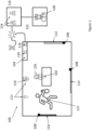
- FIG 1 shows schematically premises protected by an intruder alarm system 100 that includes an alarm device 102 (also referred to as a hold-up device).
- the intruder alarm system 100 includes a control unit 104 that is configured to receive event notifications from alarm peripherals such as door contact 106, shock sensors 108 and 108', video camera 110, microphone 111 (optionally integrated into the video camera, or stand-alone) and alarm device 102 (which itself preferably includes a microphone).
- alarm peripherals such as door contact 106, shock sensors 108 and 108', video camera 110, microphone 111 (optionally integrated into the video camera, or stand-alone) and alarm device 102 (which itself preferably includes a microphone).
- the intruder alarm system 100 has an armed state, typically in operation outside the working hours of the premises, in which in the case that the door contact 104 detects the opening of the door 112, the motion-triggered video camera 110 detects presence, or one or both of the shock sensors 108 report the detection of a shock (for example from an attempt to break or remove one or other of the windows 114), the control unit 104 reports an incident to a remote Alarm Receiving Centre 116.
- the control unit 104 may also have a disarmed mode in which it does not treat a notification received from the door contact 106, corresponding to the opening of the door 112, as an alarm event and therefore does not report the event to the ARC 116. But the control unit will typically be configured in the disarmed mode to treat notifications received from the shock sensors 108 and from the hold-up unit 102 as threats to be reported to the ARC 116.
- the control unit 104 preferably communicates wirelessly with the alarm peripherals 102-111 using a first RF transceiver 118, typically using one or more encrypted low bandwidth channels, for example in the 868Mhz ISM band.
- a second RF transceiver 120 is provided as a back-up to a wired (e.g. broadband) connection by means of which the control unit 104 can communicate with the ARC 116 over a network such as the Internet 122.
- the control unit's second transceiver 120 may communicate with the ARC 116 via a PLMN 124 (e.g., GPRS, 4G or 5G) and/or via a long range wireless link, for example using SigFox.
- PLMN 124 e.g., GPRS, 4G or 5G
- the Alarm Receiving Centre 116 typically serves many intruder alarm installations, both domestic and business, and is typically staffed by many human operatives 124 who receive and review alarm notifications, verifying them using information using e.g. video and or sound information from the installation, possibly involving an operative 124 engaging in dialogue with individuals 126 in the monitored premises. Once an alarm event is verified, the ARC or an ARC operative 124 will typically report the verified event to the police 128, but may also involve other security or emergency personnel (private security guards, ambulance or fire response teams, etc.). For example, a salesperson 126 in a jewellery feeling threatened by the behaviour of an apparent villain 127 who seems to be attempting to steal, may activate the alarm device 102 mounted beneath her desk.
- the control unit 104 will treat this notification as an alarm event and report it to the ARC 116, where an operative 124 will review the report and may check video and audio files, and "listen in” "live” to activity in the monitored premises using microphone 111 and possibly camera 110. Once the existence of a robbery or other serious threat is verified, the operative 124 may communicate this state of affairs to the police, possibly also supplying video/sound files to the police.
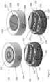
- Figure 2 shows perspective views of two alarm devices potentially suitable for use in the Figure 1 system 100.
- a single-button alarm device 201 is shown on the left.
- a corresponding two-button device 202 On the right is a corresponding two-button device 202.
- the device In both cases the device is shown with a front assembly (205, 206), including the one (211) or two (212A, 212B) "buttons" separated from its respective case assembly (203, 203').
- the case assemblies 203 and 203' may be identical, and it may be seen that the two case assemblies each have a single switch actuating button 207 which is acted upon either by the single button of the one-button device 201 or by the two buttons of the two-button device 202 - as will be explained below.
- the case assemblies 203/203' may contain a pcb (not shown) to which is mounted the switch (not expressly shown, although the actuating button 207 which is shown may be an element of the switch). That is, the actuating button 207 may be an element of the switch (as here), or it may be a separate element that works in conjunction with a separate switch.
- the case assemblies 203/203' also contain the device's electronics, which will be described later with reference to Figure 7 , together with a battery power supply.
- the electronics are preferably also mounted to the pcb to which the switch is mounted, but in some cases some or all of the electronics may be mounted to another pcb. It will be appreciated that most of the device's cost of parts and assembly are incurred with respect to manufacturing the sub-assembly 203.
- the front assemblies are secured to the respective case assembly by means of one or more releasable fasteners 208, one of which is shown.
- the case assemblies each include one or more apertures 209 (two in the examples shown) to receive a fastening screw to enable the hold-up device to be secured to a suitable substrate, such as the underside of a desk or table.
- the device may be secured in situ using adhesive on its underside, even though apertures 209 are preferably provided for use with fastening screws.
- three apertures 210 each to receive a screw used for fastening together upper (219, 219') and lower (220, 220') parts of the case assembly.
- hold-up devices are each in the form of generally circular cylindrical bodies with the or each "button" exposed by a circular aperture in an annular body which is part of the front assembly, and which provides the outer case of the device.
- hold-up devices according to the disclosure may be provided in other forms - such as angular (e.g. square, rectangular or triangular), or other curved forms (ovals, ellipses).
- a pair of slots 230 to receive (in this case) a pair of batteries (e.g. 2 AA batteries, one to each slot 230).
- a pair of batteries e.g. 2 AA batteries, one to each slot 230.
- the switch actuator 207 is positioned between the positions of the two batteries (as defined in this example by the pair of slots 230). Such an arrangement helps in designing a compact alarm device.
- a microphone which is operatively connected to a processor of the alarm unit 102.
- FIG. 3 shows constituent parts of the two-button front assembly 202 together with a view into the underside of the front assembly showing some of the constituent parts.
- the front assembly comprises an outer housing 300 which in this example is generally cylindrical in shape with a dished (concave) annular outer end face 302 having an inner circular aperture 304 within which is received a flexible cap 306.
- the cap 306 has an inner portion 308, whose outer periphery fits within and optionally protrudes through the aperture 304, and an integral outer portion or skirt 310 which in use is sealed against the inner end face of the housing about the aperture 304.
- the cap 306 also protects the electronics of the hold-up device against the ingress of liquids, and helps to prevent the ingress of dust, food crumbs, and other particulate matter that might otherwise interfere with the working of the hold-up device.
- the flexible cap 306 functions as a cover for the two actuating buttons of the hold-up device 202.
- the two actuating buttons are provided as integral elements 312 and 314 of a button bridge 316.
- the two buttons 312 and 314 are in the form of segments of a circle, but as noted previously other button shapes (angular, such as square, rectangular, triangular, or curved, such as ellipses) may be used instead.
- the two buttons 312/314 each constitute a press portion.
- the two buttons are here formed integrally with a central rib 318 that bisects the circle effectively defined by the outer perimeter of the two buttons.
- the central rib 318 has at each end a projection 320 that extends away from the surface of the button bridge that faces towards the cap 306.
- Each of the projections includes a lug 321 which engages with a corresponding socket 329 in the seesaw ring 326.
- the central rib 318 is also provided with a pair of support features or legs 322 that, when the hold-up device is assembled, rest on and are supported by the upper part 219 of the case assembly.
- the element of the case assembly that supports the legs 322 is the PCB upon which the electronics of the hold-up device are mounted.
- the central rib 318 is also flanged, with a flange running part way along each side of the length of the rib between each leg 322 and the nearest end projection 320, the flanges also extending away from the surface of the button bridge that faces towards the cap 306.
- the central rib's flanges and legs 322 render the central rib relatively stiff, and the legs 322 provide support for the central rib that enables the central rib to maintain its form even if a user inadvertently presses the rib rather than one or other of the buttons 312, 314.
- the buttons 312 and 314 are also relatively rigid but are (in the illustrated example) connected to the central rib by flexible portions 324 that permit the buttons to flex (tilt) with respect to the central rib 318.
- the outer periphery 310 of the cap 306 is shown as including a set of apertures to enable the inner portion to be secured to the housing.
- screws may be used with corresponding apertures on the inner end face of the housing or with hollow bosses formed on the inner end face of the housing, alternatively there may be provided a series of studs (or hollow bosses) extending from the inner face of the annular end of the outer housing that can be processed with heat and pressure to secure the cap and the housing together by "heat staking".
- Heat staking using hollow bosses, to produce enlarged heads that keep the parts together, is preferred from the points of view of cost and ease of assembly.
- a "seesaw ring” 326 that comprises an annular body 328 which carries, by means of flexible support elements 330, a “seesaw” or tiltable element 332 which is relatively rigid but which by virtue of the flexible support elements 330 can flex with respect to the annular body 328.
- the part between the two flexible support elements 330 functions as a lever with respect to a switch actuator - as will be explained later.
- the flexible support elements 330 hold the tiltable element 332 in the neutral rest position (shown) but also permit the tiltable element 332 to be displaced out of the plane of the seesaw ring 326 (although, while not preferred, the neutral rest position of the tiltable element could lie outside of the plane of the annular body 328), with one or both ends of the tiltable element 332 being displaced, by actuation of one or both of the buttons 312 and 314.
- the flexible support elements 330 constitute biasing means or a biasing arrangement that provides a restorative bias that tends to hold the tiltable element 332 in the rest or neutral position.
- the annular body 328 is provided with a set of apertures 331 that match those 311 of the cap, so that the seesaw ring 326 and the cap 306 can together be secured to the housing 300, for example using screws 333, or more preferably by heat staking (as previously described).
- the lever of the tiltable element 332 fits within and extends through the gap between the pair of legs 322 on the button bridge 316.
- the legs also act to constrain movement of the tiltable element 332 to help ensure that it stays centred over the switch (or switch actuator). More particularly, the legs prevent the tiltable element from moving side to side (or up and down when considered in the context of Figure 3C ) to ensure that it remains correctly positioned with respect to the switch/actuator.
- the button bridge 316 is sandwiched between the cap 306 and the seesaw ring 326.
- That part of the tiltable element 332 between the legs 322 includes a pad 334 on the side that faces away from the cap (and that faces the case assembly when the hold-up unit is assembled).
- the pad may include an indented surface to help ensure correct placement of the tiltable element 332 over the switch, but it could alternatively be a completely flat surface.
- the pad 334 acts on a switch or on an element ( a switch actuator) that transfers force to the switch, as will be explained below.
- the function of the tiltable element 332 will be explained with reference to Figures 4A to 4C .
- FIG 4A is a schematic diagram illustrating cooperation between some of the elements of a hold-up device such as that illustrated in Figures 2 and 3 , and for ease of comprehension reference numerals from Figure 3 have been used where possible.
- Element 400 represents a switch actuator
- 402 represents a reaction surface (for example, corresponding to the PCB or some other surface with respect to which the PCB is fixed) with respect to which the legs 322 are fixed.
- the operating parts of a switch are located between the switch actuator 400 and the reaction surface 402.
- the actuator is actually part of the switch, but it could instead be provided as a separate element.
- the switch is a metal dome switch which provides tactile feedback of operation (from flexing of the metal dome).
- the tiltable element 332 is shown as being supported by a biasing means or a biasing arrangements 404 and 404' that provides a restorative bias that tends to hold the tiltable element 332 in the rest or neutral position.
- a biasing means or a biasing arrangements 404 and 404' that provides a restorative bias that tends to hold the tiltable element 332 in the rest or neutral position.
- the biasing arrangements 404 and 404' are shown as being positioned at the ends of the tiltable element 332, in practice they may be provided at points intermediate the position of the switch actuator 400 and the ends of the tiltable element 332.
- the biasing force provided by biasing arrangements 404 and 404' operates in addition to the switch force (and any extra force biasing associated with the switch actuator) to define the force that must be overcome to operate the switch.
- Figure 4B corresponds to Figure 4A illustrates operation of the tiltable element 332, in particular its behaviour when only one of the buttons 312, 314 is pressed (manipulated).
- the biasing arrangements 404 and 404' are not shown in Figures 4B or 4C .
- button 314 alone has been pressed. It can be seen that button 314 has tilted with respect to central rib 318, and this has resulted in the tiltable element 332 being displaced from its neutral rest position. But because only one of the buttons has been pressed, the tiltable element has tilted without depressing element 400 (or at least not enough to activate the switch).
- a user By pressing button 314 with sufficient force to overcome the biasing force provided by biasing arrangement 404' a user causes the tiltable element to tilt as shown without activating the switch.
- an end stop is provided to limit the extent of the movement of the button 314.
- the substrate 402 may provide the end stop, although in the illustrated embodiments the end stop is provided by an upper surface of a battery holder of the device (the upper surface can be seen as item 540 in the cross-sectional drawings of Figure 5 ).
- the Figure shows the tiltable element in contact with the switch actuator and also shows the left hand end of the tiltable element as moving upwards with respect to the neutral (balanced) position with the switch actuator functioning as a fulcrum about which the tiltable element pivots without the switch being activated.
- the switch actuator resists movement along its actuation axis as a result of the force required to operate the switch together with the force required to overcome any bias and stiction in the switch actuator itself. If this cumulative force is greater than the force applicable through the operation of just one of the buttons, then the switch actuator will act as a fulcrum.
- the described operating behaviour can also be provided by a mechanism in which in the neutral (rest) position the tiltable element 332 is not in contact with the switch actuator 400, provided that actuating both buttons results in sufficient displacement of the tiltable element 332 to activate the switch.
- the switch actuator acts as a fulcrum for the tiltable element 332.
- Figure 4B also illustrates how the strength and rigidity of the legs 322 are such that even quite significant force 406 can be applied, even directly in line with the switch actuator 400, without the switch being activated.
- Figure 4C shows how, if sufficient force is applied to both of the buttons the tiltable element is displaced sufficiently to press down on the switch actuator 400, causing the switch to be activated.
- the switch is preferably a tactile switch, that is one which provides tactile feedback when the switch changes state.
- the switch may for example be a snap dome switch, optionally with a metal dome to provide good tactile feedback and long life even if used very infrequently.
- a suitable switch force may be in the range of 2 to 3 Newtons, for example 2.5 to 2.7 N, e.g. 2.6N.
- activation of the switch requires the two buttons to be in the depressed state at the same time, but it is not necessary for the actions of depressing two buttons to be simultaneous - one can be depressed first and then the other depressed while the first is already in the depressed state.
- the tiltable element (lever) 332 and the switch actuator 400 constitute a mechanism intermediate the pair of operators and the switch that is so configured that manual displacement of only a single one of the operators is ineffective to operate the switch, but manual displacement of the pair of operators together results in operation of the switch.
- the mechanism is capable of converting movement of the press portions 312/314 into movement of the switch.
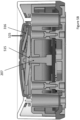
- Figure 5A represents a vertical cross-section through a two-button device such as that illustrated as device 202 in Figures 2 and 3 .
- the section is along the longitudinal axis of the tiltable element 332.
- the PCB may be retained between the base member 220 and the upper part 219.
- the switch actuator 207 extends between the underside of the tiltable element 332 and the PCB 500 on which is mounted the switch 520.
- the switch 520 is preferably a dome switch, for example a metal dome switch.
- the Figure also shows screws 530 securing together the upper 219 and lower 220 parts of the case assembly.
- the Figure also shows the presence of a cover of a battery holder, the upper surface 540 of which serves as an end stop for the tiltable element 332.
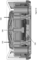
- Figure 5B corresponds to Figure 5A , albeit somewhat simplified for ease of illustration, and shows schematically the effect of depressing only one of the buttons (in this case the right hand one, 314) by applying a force 525: the tiltable element 332 tilts by pivoting about the point labelled 515 on the switch actuating element 207, that is the switch actuator operates as a fulcrum for the lever of the tiltable element.
- the tiltable element 332 tilts by pivoting about the point labelled 515 on the switch actuating element 207, that is the switch actuator operates as a fulcrum for the lever of the tiltable element.
- Figure 5C also corresponds to Figure 5A , and shows schematically the effect of depressing both the buttons by the application of forces 532 and 534: the tiltable element 332 is depressed, rather than merely being tilted, and is effective to operate the switch 520 by depressing the switch actuator 207, behaving as shown in Figure 4B .
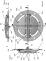
- FIGS 6 , 6A and 6B show in more detail the relationship between the button bridge 316 and the seesaw ring 326 by means of a plan view and a pair of vertical sections taken respectively along the lines A-A and B-B.
- the tiltable element 332 which is here shown in longitudinal section, has on its upper surface (that in the assembled device faces the button cap 316), at its two ends, upstanding lugs 600.
- the tiltable element 332 also tapers, with its thickness generally reducing from its centre towards its two ends (although the two lugs 600 increase its thickness at the ends) - by means of a sloping lower surface.
- the reduced thickness of the hinge elements 324, compared to the thickness of the button portions 312/314 of the button cap 316 can also be seen clearly.
- the button bridge 316 and the seesaw ring 326 may be made from suitable engineering plastics which provide the necessary resilience and dimensional stability, such as for example ABS, polycarbonates, polyamides, and polypropylenes. Different material types or specifications may of course be chosen for the two different components, in light of the different types of movement involved - in particular the different demands placed on the materials that provide the flexible portions 324 of the button bridge 316 and the flexible support elements 330 of the seesaw ring. Polycarbonate, ABS, or 50% glass-filled poly-acetate are generally suitable choices as the material of the housing of the front assembly and for the upper (219, 219') and lower (220, 220') parts of the case assembly.
- the cap 316 is preferably made of a durable elastomer such as TPE or a suitable silicone elastomer.
- the two operators which a user must operate in order to activate the switch to generate a hold-up signal are each hinged on one side so that they tilt in moving between their rest and activation positions.
- the one-piece button bridge that has been described is perhaps the easiest and most convenient way to provide this functionality, but various multi-part constructions in which the two operators rotate about one or more pivots, and are biased into their rest position by integral biasing arrangements or one or more separate springs could also be devised - albeit with a potentially significant increase in component count, complexity and cost
- the activation mechanism could also be designed so that instead of a tilting movement, the two operators undergo a linear translation between their rest and activation positions, preferably being spring biased into their rest position.
- the simplicity, low component count, and likely reliability and durability of the mechanism illustrated are however clearly very advantageous compared to these other possible solutions and are consequently strongly preferred.
- the alarm (hold-up) devices thus far described do not latch in the activated position: a user is given tactile feedback during successful activation (operation) of the switch, and activation of the switch is sufficient to cause the electronics of the device to transmit a hold up signal to the control unit 104 of the security monitoring system 100.
- the device 102 may be configured to repeat transmission of the hold-up signal until an acknowledgement is received from the control unit 104 of the security monitoring system 100.
- This non-latching behaviour is the preferred approach, because it avoids the need to engineer and provide both a latching mechanism and an unlatching mechanism (some known devices latch upon activation, and then need manually to be unlocked from the latched position as part of a physical intervention, for example by security staff).
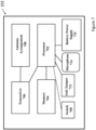
- FIG. 7 shows schematically the main electrical components of an alarm (hold-up) device, according to various embodiments, which is an example of device 102.
- the device 102 is configured to transmit an alarm signal in the event that the switch 700 is activated, and for this purpose the device 102 is controlled by a processor or microcontroller 702, which has an associated memory 704, and a transceiver 706.
- the transceiver 706, which has an associated antenna arrangement 708, communicates with the controller 104 of the security monitoring system 100.
- the transceiver 706 and the controller 104 communicate using a low bandwidth channel carried over one or more permitted frequencies in an Industrial Scientific and Medical (ISM) band, such as the European 868 MHz band (or equivalent in other regions/countries).
- ISM Industrial Scientific and Medical
- transmissions between the hold-up device 102 and the controller 104 (and vice versa) are encrypted.
- the device 102 includes a battery power supply 710 which powers the processor and the transceiver and which preferably has an energy storage capacity sufficient to power the device 102 for at least 3 years.
- the device 102 also preferably includes an anti-tamper arrangement 712 which is coupled to the processor 702.
- the anti-tamper arrangement is preferably configured to provide a signal (possibly as the result of a switch going open circuit, or as the result of a switch circuit being closed) in the event that an attempt is made to remove the device 102 from the surface to which it is secured or in the event that an attempt is made to dismantle the device (e.g. to remove the front assembly from the case assembly, or to remove the button bridge 316 from within the device).
- the device 102 preferably also includes a microphone 714, coupled to the processor 702.
- the processor is preferably so configured that, when a security event has been reported to an alarm receiving centre (or some other monitoring entity), audio signals received by the processor from the microphone are supplied to the alarm receiving centre (or other monitoring entity), so that agents reacting to the report of a security event are able to make use of the received audio signals in verifying whether the reported security event is a false alarm or not. If the reported security event is verified to be a real security or alarm event, and not a false alarm, the monitoring agent can report the event to the police (under other circumstances an intervention may be arranged, for example using private security or other personnel).
Landscapes
- Business, Economics & Management (AREA)
- Emergency Management (AREA)
- Physics & Mathematics (AREA)
- General Physics & Mathematics (AREA)
- Burglar Alarm Systems (AREA)
- Emergency Alarm Devices (AREA)
Priority Applications (3)
| Application Number | Priority Date | Filing Date | Title |
|---|---|---|---|
| EP22173205.0A EP4276786A1 (de) | 2022-05-13 | 2022-05-13 | Alarmvorrichtung |
| PCT/EP2023/050630 WO2023217418A1 (en) | 2022-05-13 | 2023-01-12 | Alarm device |
| CL2024003459A CL2024003459A1 (es) | 2022-05-13 | 2024-11-12 | Dispositivo de alarma |
Applications Claiming Priority (1)
| Application Number | Priority Date | Filing Date | Title |
|---|---|---|---|
| EP22173205.0A EP4276786A1 (de) | 2022-05-13 | 2022-05-13 | Alarmvorrichtung |
Publications (1)
| Publication Number | Publication Date |
|---|---|
| EP4276786A1 true EP4276786A1 (de) | 2023-11-15 |
Family
ID=81653493
Family Applications (1)
| Application Number | Title | Priority Date | Filing Date |
|---|---|---|---|
| EP22173205.0A Pending EP4276786A1 (de) | 2022-05-13 | 2022-05-13 | Alarmvorrichtung |
Country Status (3)
| Country | Link |
|---|---|
| EP (1) | EP4276786A1 (de) |
| CL (1) | CL2024003459A1 (de) |
| WO (1) | WO2023217418A1 (de) |
Citations (3)
| Publication number | Priority date | Publication date | Assignee | Title |
|---|---|---|---|---|
| EP1521225A1 (de) * | 2003-09-30 | 2005-04-06 | Safety Technology International (Europe) Limited | Notrufschalter |
| AU2010100382A4 (en) * | 2010-04-27 | 2010-05-27 | Dfm International Pty Ltd | Dual Press Panic Buttons |
| WO2018014974A1 (en) * | 2016-07-22 | 2018-01-25 | Pålsson Hanne | Alarm triggering device and circuitry therefor |
-
2022
- 2022-05-13 EP EP22173205.0A patent/EP4276786A1/de active Pending
-
2023
- 2023-01-12 WO PCT/EP2023/050630 patent/WO2023217418A1/en not_active Ceased
-
2024
- 2024-11-12 CL CL2024003459A patent/CL2024003459A1/es unknown
Patent Citations (3)
| Publication number | Priority date | Publication date | Assignee | Title |
|---|---|---|---|---|
| EP1521225A1 (de) * | 2003-09-30 | 2005-04-06 | Safety Technology International (Europe) Limited | Notrufschalter |
| AU2010100382A4 (en) * | 2010-04-27 | 2010-05-27 | Dfm International Pty Ltd | Dual Press Panic Buttons |
| WO2018014974A1 (en) * | 2016-07-22 | 2018-01-25 | Pålsson Hanne | Alarm triggering device and circuitry therefor |
Also Published As
| Publication number | Publication date |
|---|---|
| WO2023217418A1 (en) | 2023-11-16 |
| CL2024003459A1 (es) | 2025-01-24 |
Similar Documents
| Publication | Publication Date | Title |
|---|---|---|
| EP1924980B1 (de) | Leitfähiger manipulationsschalter für sicherheitseinrichtungen | |
| CA2504001C (en) | Push plate assembly | |
| US7889088B1 (en) | Extended smoke alarm system | |
| US8203090B2 (en) | Switch assembly | |
| US7187280B2 (en) | Alarm system with thin profile | |
| EP4276786A1 (de) | Alarmvorrichtung | |
| CN210605988U (zh) | 门铃 | |
| US7714734B1 (en) | Extended smoke alarm system | |
| EP1627368B1 (de) | Call-punkte | |
| SK3882001A3 (en) | Door terminal comprising a cover for the emergency button | |
| US5469139A (en) | Door block alarm | |
| JPH09184332A (ja) | サッシ | |
| US20060033597A1 (en) | Wireless safety alarm with enlarged actuator button | |
| KR100398176B1 (ko) | 금고 | |
| CN115020139A (zh) | 呼叫开关 | |
| JP2003099858A (ja) | 防犯機能付クレセントおよび防犯システム | |
| CN221220063U (zh) | 嵌入式智能门锁 | |
| EP4550287A1 (de) | Sicherheitsperipheriegerät | |
| JP4311513B2 (ja) | 押しボタンスイッチ | |
| KR200346258Y1 (ko) | 무선방범경비장치 | |
| KR200252007Y1 (ko) | 비상호출용 스위치장치 | |
| CN210166896U (zh) | 一种小型智能安防监控主机 | |
| JP3458274B2 (ja) | 家屋用防犯装置 | |
| KR200406861Y1 (ko) | 휴대용 도난방지 알림장치 | |
| JP3103031U (ja) | ホームセキュリティシステム |
Legal Events
| Date | Code | Title | Description |
|---|---|---|---|
| PUAI | Public reference made under article 153(3) epc to a published international application that has entered the european phase |
Free format text: ORIGINAL CODE: 0009012 |
|
| STAA | Information on the status of an ep patent application or granted ep patent |
Free format text: STATUS: THE APPLICATION HAS BEEN PUBLISHED |
|
| AK | Designated contracting states |
Kind code of ref document: A1 Designated state(s): AL AT BE BG CH CY CZ DE DK EE ES FI FR GB GR HR HU IE IS IT LI LT LU LV MC MK MT NL NO PL PT RO RS SE SI SK SM TR |
|
| STAA | Information on the status of an ep patent application or granted ep patent |
Free format text: STATUS: REQUEST FOR EXAMINATION WAS MADE |
|
| 17P | Request for examination filed |
Effective date: 20240513 |
|
| RBV | Designated contracting states (corrected) |
Designated state(s): AL AT BE BG CH CY CZ DE DK EE ES FI FR GB GR HR HU IE IS IT LI LT LU LV MC MK MT NL NO PL PT RO RS SE SI SK SM TR |
|
| STAA | Information on the status of an ep patent application or granted ep patent |
Free format text: STATUS: EXAMINATION IS IN PROGRESS |
|
| 17Q | First examination report despatched |
Effective date: 20250319 |