EP4277675B1 - Dispositif de diurèse artificielle - Google Patents
Dispositif de diurèse artificielle Download PDFInfo
- Publication number
- EP4277675B1 EP4277675B1 EP22705874.0A EP22705874A EP4277675B1 EP 4277675 B1 EP4277675 B1 EP 4277675B1 EP 22705874 A EP22705874 A EP 22705874A EP 4277675 B1 EP4277675 B1 EP 4277675B1
- Authority
- EP
- European Patent Office
- Prior art keywords
- ultra
- box
- inlet
- liquid
- interaction area
- Prior art date
- Legal status (The legal status is an assumption and is not a legal conclusion. Google has not performed a legal analysis and makes no representation as to the accuracy of the status listed.)
- Active
Links
Images


Classifications
-
- A—HUMAN NECESSITIES
- A61—MEDICAL OR VETERINARY SCIENCE; HYGIENE
- A61M—DEVICES FOR INTRODUCING MEDIA INTO, OR ONTO, THE BODY; DEVICES FOR TRANSDUCING BODY MEDIA OR FOR TAKING MEDIA FROM THE BODY; DEVICES FOR PRODUCING OR ENDING SLEEP OR STUPOR
- A61M1/00—Suction or pumping devices for medical purposes; Devices for carrying-off, for treatment of, or for carrying-over, body-liquids; Drainage systems
- A61M1/36—Other treatment of blood in a by-pass of the natural circulatory system, e.g. temperature adaptation, irradiation ; Extra-corporeal blood circuits
- A61M1/3606—Arrangements for blood-volume reduction of extra-corporeal circuits
-
- A—HUMAN NECESSITIES
- A61—MEDICAL OR VETERINARY SCIENCE; HYGIENE
- A61M—DEVICES FOR INTRODUCING MEDIA INTO, OR ONTO, THE BODY; DEVICES FOR TRANSDUCING BODY MEDIA OR FOR TAKING MEDIA FROM THE BODY; DEVICES FOR PRODUCING OR ENDING SLEEP OR STUPOR
- A61M1/00—Suction or pumping devices for medical purposes; Devices for carrying-off, for treatment of, or for carrying-over, body-liquids; Drainage systems
- A61M1/14—Dialysis systems; Artificial kidneys; Blood oxygenators ; Reciprocating systems for treatment of body fluids, e.g. single needle systems for hemofiltration or pheresis
- A61M1/15—Dialysis systems; Artificial kidneys; Blood oxygenators ; Reciprocating systems for treatment of body fluids, e.g. single needle systems for hemofiltration or pheresis with a cassette forming partially or totally the flow circuit for the treating fluid, e.g. the dialysate fluid circuit or the treating gas circuit
- A61M1/152—Details related to the interface between cassette and machine
-
- A—HUMAN NECESSITIES
- A61—MEDICAL OR VETERINARY SCIENCE; HYGIENE
- A61M—DEVICES FOR INTRODUCING MEDIA INTO, OR ONTO, THE BODY; DEVICES FOR TRANSDUCING BODY MEDIA OR FOR TAKING MEDIA FROM THE BODY; DEVICES FOR PRODUCING OR ENDING SLEEP OR STUPOR
- A61M1/00—Suction or pumping devices for medical purposes; Devices for carrying-off, for treatment of, or for carrying-over, body-liquids; Drainage systems
- A61M1/14—Dialysis systems; Artificial kidneys; Blood oxygenators ; Reciprocating systems for treatment of body fluids, e.g. single needle systems for hemofiltration or pheresis
- A61M1/15—Dialysis systems; Artificial kidneys; Blood oxygenators ; Reciprocating systems for treatment of body fluids, e.g. single needle systems for hemofiltration or pheresis with a cassette forming partially or totally the flow circuit for the treating fluid, e.g. the dialysate fluid circuit or the treating gas circuit
- A61M1/154—Dialysis systems; Artificial kidneys; Blood oxygenators ; Reciprocating systems for treatment of body fluids, e.g. single needle systems for hemofiltration or pheresis with a cassette forming partially or totally the flow circuit for the treating fluid, e.g. the dialysate fluid circuit or the treating gas circuit with sensing means or components thereof
-
- A—HUMAN NECESSITIES
- A61—MEDICAL OR VETERINARY SCIENCE; HYGIENE
- A61M—DEVICES FOR INTRODUCING MEDIA INTO, OR ONTO, THE BODY; DEVICES FOR TRANSDUCING BODY MEDIA OR FOR TAKING MEDIA FROM THE BODY; DEVICES FOR PRODUCING OR ENDING SLEEP OR STUPOR
- A61M1/00—Suction or pumping devices for medical purposes; Devices for carrying-off, for treatment of, or for carrying-over, body-liquids; Drainage systems
- A61M1/14—Dialysis systems; Artificial kidneys; Blood oxygenators ; Reciprocating systems for treatment of body fluids, e.g. single needle systems for hemofiltration or pheresis
- A61M1/15—Dialysis systems; Artificial kidneys; Blood oxygenators ; Reciprocating systems for treatment of body fluids, e.g. single needle systems for hemofiltration or pheresis with a cassette forming partially or totally the flow circuit for the treating fluid, e.g. the dialysate fluid circuit or the treating gas circuit
- A61M1/156—Constructional details of the cassette, e.g. specific details on material or shape
- A61M1/1563—Details of incorporated filters
-
- A—HUMAN NECESSITIES
- A61—MEDICAL OR VETERINARY SCIENCE; HYGIENE
- A61M—DEVICES FOR INTRODUCING MEDIA INTO, OR ONTO, THE BODY; DEVICES FOR TRANSDUCING BODY MEDIA OR FOR TAKING MEDIA FROM THE BODY; DEVICES FOR PRODUCING OR ENDING SLEEP OR STUPOR
- A61M1/00—Suction or pumping devices for medical purposes; Devices for carrying-off, for treatment of, or for carrying-over, body-liquids; Drainage systems
- A61M1/34—Filtering material out of the blood by passing it through a membrane, i.e. hemofiltration or diafiltration
- A61M1/3401—Cassettes therefor
-
- A—HUMAN NECESSITIES
- A61—MEDICAL OR VETERINARY SCIENCE; HYGIENE
- A61M—DEVICES FOR INTRODUCING MEDIA INTO, OR ONTO, THE BODY; DEVICES FOR TRANSDUCING BODY MEDIA OR FOR TAKING MEDIA FROM THE BODY; DEVICES FOR PRODUCING OR ENDING SLEEP OR STUPOR
- A61M1/00—Suction or pumping devices for medical purposes; Devices for carrying-off, for treatment of, or for carrying-over, body-liquids; Drainage systems
- A61M1/34—Filtering material out of the blood by passing it through a membrane, i.e. hemofiltration or diafiltration
- A61M1/3403—Regulation parameters
- A61M1/3406—Physical characteristics of the filtrate, e.g. urea
-
- A—HUMAN NECESSITIES
- A61—MEDICAL OR VETERINARY SCIENCE; HYGIENE
- A61M—DEVICES FOR INTRODUCING MEDIA INTO, OR ONTO, THE BODY; DEVICES FOR TRANSDUCING BODY MEDIA OR FOR TAKING MEDIA FROM THE BODY; DEVICES FOR PRODUCING OR ENDING SLEEP OR STUPOR
- A61M1/00—Suction or pumping devices for medical purposes; Devices for carrying-off, for treatment of, or for carrying-over, body-liquids; Drainage systems
- A61M1/34—Filtering material out of the blood by passing it through a membrane, i.e. hemofiltration or diafiltration
- A61M1/3403—Regulation parameters
- A61M1/341—Regulation parameters by measuring the filtrate rate or volume
-
- A—HUMAN NECESSITIES
- A61—MEDICAL OR VETERINARY SCIENCE; HYGIENE
- A61M—DEVICES FOR INTRODUCING MEDIA INTO, OR ONTO, THE BODY; DEVICES FOR TRANSDUCING BODY MEDIA OR FOR TAKING MEDIA FROM THE BODY; DEVICES FOR PRODUCING OR ENDING SLEEP OR STUPOR
- A61M1/00—Suction or pumping devices for medical purposes; Devices for carrying-off, for treatment of, or for carrying-over, body-liquids; Drainage systems
- A61M1/34—Filtering material out of the blood by passing it through a membrane, i.e. hemofiltration or diafiltration
- A61M1/3496—Plasmapheresis; Leucopheresis; Lymphopheresis
-
- A—HUMAN NECESSITIES
- A61—MEDICAL OR VETERINARY SCIENCE; HYGIENE
- A61M—DEVICES FOR INTRODUCING MEDIA INTO, OR ONTO, THE BODY; DEVICES FOR TRANSDUCING BODY MEDIA OR FOR TAKING MEDIA FROM THE BODY; DEVICES FOR PRODUCING OR ENDING SLEEP OR STUPOR
- A61M1/00—Suction or pumping devices for medical purposes; Devices for carrying-off, for treatment of, or for carrying-over, body-liquids; Drainage systems
- A61M1/36—Other treatment of blood in a by-pass of the natural circulatory system, e.g. temperature adaptation, irradiation ; Extra-corporeal blood circuits
- A61M1/3621—Extra-corporeal blood circuits
- A61M1/3622—Extra-corporeal blood circuits with a cassette forming partially or totally the blood circuit
- A61M1/36222—Details related to the interface between cassette and machine
-
- A—HUMAN NECESSITIES
- A61—MEDICAL OR VETERINARY SCIENCE; HYGIENE
- A61M—DEVICES FOR INTRODUCING MEDIA INTO, OR ONTO, THE BODY; DEVICES FOR TRANSDUCING BODY MEDIA OR FOR TAKING MEDIA FROM THE BODY; DEVICES FOR PRODUCING OR ENDING SLEEP OR STUPOR
- A61M1/00—Suction or pumping devices for medical purposes; Devices for carrying-off, for treatment of, or for carrying-over, body-liquids; Drainage systems
- A61M1/36—Other treatment of blood in a by-pass of the natural circulatory system, e.g. temperature adaptation, irradiation ; Extra-corporeal blood circuits
- A61M1/3621—Extra-corporeal blood circuits
- A61M1/3622—Extra-corporeal blood circuits with a cassette forming partially or totally the blood circuit
- A61M1/36224—Extra-corporeal blood circuits with a cassette forming partially or totally the blood circuit with sensing means or components thereof
-
- A—HUMAN NECESSITIES
- A61—MEDICAL OR VETERINARY SCIENCE; HYGIENE
- A61M—DEVICES FOR INTRODUCING MEDIA INTO, OR ONTO, THE BODY; DEVICES FOR TRANSDUCING BODY MEDIA OR FOR TAKING MEDIA FROM THE BODY; DEVICES FOR PRODUCING OR ENDING SLEEP OR STUPOR
- A61M1/00—Suction or pumping devices for medical purposes; Devices for carrying-off, for treatment of, or for carrying-over, body-liquids; Drainage systems
- A61M1/36—Other treatment of blood in a by-pass of the natural circulatory system, e.g. temperature adaptation, irradiation ; Extra-corporeal blood circuits
- A61M1/3621—Extra-corporeal blood circuits
- A61M1/3626—Gas bubble detectors
-
- A—HUMAN NECESSITIES
- A61—MEDICAL OR VETERINARY SCIENCE; HYGIENE
- A61M—DEVICES FOR INTRODUCING MEDIA INTO, OR ONTO, THE BODY; DEVICES FOR TRANSDUCING BODY MEDIA OR FOR TAKING MEDIA FROM THE BODY; DEVICES FOR PRODUCING OR ENDING SLEEP OR STUPOR
- A61M1/00—Suction or pumping devices for medical purposes; Devices for carrying-off, for treatment of, or for carrying-over, body-liquids; Drainage systems
- A61M1/36—Other treatment of blood in a by-pass of the natural circulatory system, e.g. temperature adaptation, irradiation ; Extra-corporeal blood circuits
- A61M1/3621—Extra-corporeal blood circuits
- A61M1/3639—Blood pressure control, pressure transducers specially adapted therefor
-
- A—HUMAN NECESSITIES
- A61—MEDICAL OR VETERINARY SCIENCE; HYGIENE
- A61M—DEVICES FOR INTRODUCING MEDIA INTO, OR ONTO, THE BODY; DEVICES FOR TRANSDUCING BODY MEDIA OR FOR TAKING MEDIA FROM THE BODY; DEVICES FOR PRODUCING OR ENDING SLEEP OR STUPOR
- A61M1/00—Suction or pumping devices for medical purposes; Devices for carrying-off, for treatment of, or for carrying-over, body-liquids; Drainage systems
- A61M1/36—Other treatment of blood in a by-pass of the natural circulatory system, e.g. temperature adaptation, irradiation ; Extra-corporeal blood circuits
- A61M1/3621—Extra-corporeal blood circuits
- A61M1/3643—Priming, rinsing before or after use
-
- G—PHYSICS
- G01—MEASURING; TESTING
- G01F—MEASURING VOLUME, VOLUME FLOW, MASS FLOW OR LIQUID LEVEL; METERING BY VOLUME
- G01F1/00—Measuring the volume flow or mass flow of fluid or fluent solid material wherein the fluid passes through a meter in a continuous flow
- G01F1/68—Measuring the volume flow or mass flow of fluid or fluent solid material wherein the fluid passes through a meter in a continuous flow by using thermal effects
- G01F1/684—Structural arrangements; Mounting of elements, e.g. in relation to fluid flow
- G01F1/6842—Structural arrangements; Mounting of elements, e.g. in relation to fluid flow with means for influencing the fluid flow
-
- G—PHYSICS
- G01—MEASURING; TESTING
- G01F—MEASURING VOLUME, VOLUME FLOW, MASS FLOW OR LIQUID LEVEL; METERING BY VOLUME
- G01F1/00—Measuring the volume flow or mass flow of fluid or fluent solid material wherein the fluid passes through a meter in a continuous flow
- G01F1/68—Measuring the volume flow or mass flow of fluid or fluent solid material wherein the fluid passes through a meter in a continuous flow by using thermal effects
- G01F1/684—Structural arrangements; Mounting of elements, e.g. in relation to fluid flow
- G01F1/6845—Micromachined devices
-
- G—PHYSICS
- G01—MEASURING; TESTING
- G01F—MEASURING VOLUME, VOLUME FLOW, MASS FLOW OR LIQUID LEVEL; METERING BY VOLUME
- G01F1/00—Measuring the volume flow or mass flow of fluid or fluent solid material wherein the fluid passes through a meter in a continuous flow
- G01F1/68—Measuring the volume flow or mass flow of fluid or fluent solid material wherein the fluid passes through a meter in a continuous flow by using thermal effects
- G01F1/684—Structural arrangements; Mounting of elements, e.g. in relation to fluid flow
- G01F1/688—Structural arrangements; Mounting of elements, e.g. in relation to fluid flow using a particular type of heating, cooling or sensing element
- G01F1/69—Structural arrangements; Mounting of elements, e.g. in relation to fluid flow using a particular type of heating, cooling or sensing element of resistive type
-
- A—HUMAN NECESSITIES
- A61—MEDICAL OR VETERINARY SCIENCE; HYGIENE
- A61M—DEVICES FOR INTRODUCING MEDIA INTO, OR ONTO, THE BODY; DEVICES FOR TRANSDUCING BODY MEDIA OR FOR TAKING MEDIA FROM THE BODY; DEVICES FOR PRODUCING OR ENDING SLEEP OR STUPOR
- A61M2205/00—General characteristics of the apparatus
- A61M2205/12—General characteristics of the apparatus with interchangeable cassettes forming partially or totally the fluid circuit
- A61M2205/121—General characteristics of the apparatus with interchangeable cassettes forming partially or totally the fluid circuit interface between cassette and base
-
- A—HUMAN NECESSITIES
- A61—MEDICAL OR VETERINARY SCIENCE; HYGIENE
- A61M—DEVICES FOR INTRODUCING MEDIA INTO, OR ONTO, THE BODY; DEVICES FOR TRANSDUCING BODY MEDIA OR FOR TAKING MEDIA FROM THE BODY; DEVICES FOR PRODUCING OR ENDING SLEEP OR STUPOR
- A61M2205/00—General characteristics of the apparatus
- A61M2205/15—Detection of leaks
-
- A—HUMAN NECESSITIES
- A61—MEDICAL OR VETERINARY SCIENCE; HYGIENE
- A61M—DEVICES FOR INTRODUCING MEDIA INTO, OR ONTO, THE BODY; DEVICES FOR TRANSDUCING BODY MEDIA OR FOR TAKING MEDIA FROM THE BODY; DEVICES FOR PRODUCING OR ENDING SLEEP OR STUPOR
- A61M2205/00—General characteristics of the apparatus
- A61M2205/33—Controlling, regulating or measuring
- A61M2205/3306—Optical measuring means
-
- A—HUMAN NECESSITIES
- A61—MEDICAL OR VETERINARY SCIENCE; HYGIENE
- A61M—DEVICES FOR INTRODUCING MEDIA INTO, OR ONTO, THE BODY; DEVICES FOR TRANSDUCING BODY MEDIA OR FOR TAKING MEDIA FROM THE BODY; DEVICES FOR PRODUCING OR ENDING SLEEP OR STUPOR
- A61M2205/00—General characteristics of the apparatus
- A61M2205/33—Controlling, regulating or measuring
- A61M2205/3317—Electromagnetic, inductive or dielectric measuring means
-
- A—HUMAN NECESSITIES
- A61—MEDICAL OR VETERINARY SCIENCE; HYGIENE
- A61M—DEVICES FOR INTRODUCING MEDIA INTO, OR ONTO, THE BODY; DEVICES FOR TRANSDUCING BODY MEDIA OR FOR TAKING MEDIA FROM THE BODY; DEVICES FOR PRODUCING OR ENDING SLEEP OR STUPOR
- A61M2205/00—General characteristics of the apparatus
- A61M2205/33—Controlling, regulating or measuring
- A61M2205/3331—Pressure; Flow
- A61M2205/3334—Measuring or controlling the flow rate
-
- A—HUMAN NECESSITIES
- A61—MEDICAL OR VETERINARY SCIENCE; HYGIENE
- A61M—DEVICES FOR INTRODUCING MEDIA INTO, OR ONTO, THE BODY; DEVICES FOR TRANSDUCING BODY MEDIA OR FOR TAKING MEDIA FROM THE BODY; DEVICES FOR PRODUCING OR ENDING SLEEP OR STUPOR
- A61M2205/00—General characteristics of the apparatus
- A61M2205/33—Controlling, regulating or measuring
- A61M2205/3368—Temperature
- A61M2205/3372—Temperature compensation
-
- A—HUMAN NECESSITIES
- A61—MEDICAL OR VETERINARY SCIENCE; HYGIENE
- A61M—DEVICES FOR INTRODUCING MEDIA INTO, OR ONTO, THE BODY; DEVICES FOR TRANSDUCING BODY MEDIA OR FOR TAKING MEDIA FROM THE BODY; DEVICES FOR PRODUCING OR ENDING SLEEP OR STUPOR
- A61M2209/00—Ancillary equipment
- A61M2209/08—Supports for equipment
- A61M2209/084—Supporting bases, stands for equipment
-
- A—HUMAN NECESSITIES
- A61—MEDICAL OR VETERINARY SCIENCE; HYGIENE
- A61M—DEVICES FOR INTRODUCING MEDIA INTO, OR ONTO, THE BODY; DEVICES FOR TRANSDUCING BODY MEDIA OR FOR TAKING MEDIA FROM THE BODY; DEVICES FOR PRODUCING OR ENDING SLEEP OR STUPOR
- A61M2209/00—Ancillary equipment
- A61M2209/08—Supports for equipment
- A61M2209/088—Supports for equipment on the body
Definitions
- the present invention concerns an artificial diuresis device.
- the ultrafiltration equipment of known type is not commonly used to support other therapies or in departments for different pathologies due both to its cumbersomeness and the need for the presence of specialist staff. In these situations, therefore, pharmacological treatments are frequently used to support other therapies; however, pharmacological treatment is not as effective as the use of ultrafiltration equipment.
- ultrafiltration we mean an established and well-known process for the production of plasma water, but not cells or colloids, from blood containing electrolytes and cristalloids by means of separation obtained through a membrane.
- the object of the present invention is, therefore, to provide an artificial diuresis device that overcomes the drawbacks described above.
- the object of the present invention is to provide a simple, portable and safe device that makes the technique of ultrafiltration feasible in any setting, either in hospital or at home, facilitating any self-administration of the therapy by the patient.
- an artificial diuresis device is provided according to the attached claims.
- the number 1 indicates overall an artificial diuresis device according to the present invention.
- the artificial diuresis device 1 is portable, namely it can be worn by a patient H allowing movements (such as walking, sitting and the like).
- the artificial diuresis device 1 has reduced dimensions and weight so that it can be lifted and moved easily by any person.
- the device 1 is configured to work with a volume of extracorporeal blood of less than 40 ml, preferably 30 ml.
- the device 1 being portable, having reduced dimensions and working with a volume of extracorporeal blood of less than 40 ml, intrinsically reduces patient risk in the event of blood loss.
- the artificial diuresis device 1 comprises a reusable machine 2 and a disposable unit 3.
- the machine 2 comprises a box-like body 21 having an inner cavity 22; in this way, advantageously, the part of the most costly and cumbersome components of the device 1 are enclosed within the cavity 22 of the machine 2 (and are not accessible) so that they can be used several times.
- the disposable unit 3 can be used one single time and comprises components that come into contact, in use, with the organic liquids Lh of the patient H. At the end of each treatment the disposable unit 3 is disposed of in compliance with the law.
- the disposable unit is connected, in use, to the patient H by means of:
- vascular access devices N1 and N2 are needles and/or catheters or similar. Each vascular access device N1, N2 is connected, in use, to the disposable unit 3 as will be illustrated in greater detail below.
- the disposable unit 3 is completely filled, before use, with treatment liquid Lt.
- the treatment liquid Lt can be saline solution, if necessary mixed with other substances such as heparin, for example.
- the device 1 further comprises a cover 20 having substantially the form of a cup-shaped body with concavity facing, when coupled, the body 21 of the machine 2 coupled with the machine 2.
- the cover 20 covers and screens, at least partly, the disposable unit 3.
- the disposable unit 3 comprises: an operating box 4; a plurality of flexible tubes T for the flow of the organic liquids Lh; a filtering unit 5; and a collecting bag 6.
- the device 1 comprises a plurality of measuring apparatuses S, as will be illustrated in further detail below, in order to verify correct execution of the treatment.
- the device 1 further comprises a control unit 7, which is housed inside the inner cavity 22 and with which each measuring apparatus S exchanges signals, in use.
- the body 21 of the machine 2 and the box 4 are configured to couple with each other, for example by means of shape and/or interference couplings (of known type and not illustrated), in a predefined position, as will be illustrated in greater detail below.
- the box 4 is made in one single piece.
- the box 4 is made by molding of polymeric material. In this way, the box 4 is lightweight and easy to wear.
- box 4 is optimized so as to reduce the overall dimensions and thus facilitate portability.
- the box 4 is configured so as to minimize the volume of blood present in the extracorporeal circuit of the disposable unit 3.
- the box 4 is configured to limit the volume of blood present in the extracorporeal circuit to below 40 ml, preferably approximately 30 ml.
- the box 4 has:
- the box 4 has an interaction area A1 configured to interface, in use, with the machine 2.
- the interaction area A1 is arranged along the inlet channel C1.
- the interaction area A1 has a substantially cylindrical shape. Without loss of generality, the interaction area A1 can have different shapes and dimensions from those illustrated.
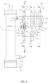
- the device 1 comprises a measuring apparatus S1 (schematized in figure 5 ) which is configured to detect the pressure of the organic liquid Lh1 to be treated in the interaction area A1.
- the box 4 comprises a membrane 30 which laterally delimits a respective portion of the interaction area A1.
- the machine 2 comprises, in turn, a pressure transducer 31 which detects, in use, variations in the pressure of the organic liquid Lh1 to be treated inside the interference area A1 according to the deformation of the membrane 31.
- the pressure transducer 31 is housed inside the cavity 22 of the machine 2 and exchanges signals (in a known manner not illustrated) with the control unit 7.
- the box 4 has an interaction area A2 configured to interface, in use, with the machine 2.
- the interaction area A2 is arranged along the outlet channel C2.
- the interaction area A2 has a substantially cylindrical shape. Without loss of generality, the interaction area A2 can have shapes and dimensions different from those illustrated.
- the device 1 comprises a measuring apparatus S2 (schematized in figure 5 ) which is configured to detect the pressure of the treated organic liquid Lh2 flowing out of the filtering unit 5 and in the area of the interaction area A2.
- the box 4 comprises a membrane 32 that laterally delimits a respective portion of the interaction area A2.
- the machine 2 comprises, in turn, a pressure transducer 33 which detects, in use, variations in the pressure of the treated organic liquid Lh2 inside the interference area A2 according to the deformation of the membrane 32.
- the pressure transducer 33 is housed inside the cavity 22 of the machine 2 and exchanges signals (in a known manner not illustrated) with the control unit 7.
- the box 4 furthermore has:
- the box 4 furthermore has an inlet I4 for introducing auxiliary liquid LA into the ultra-filtered channel C3.
- the auxiliary liquid LA can correspond to the treatment liquid Lt or be of different type.
- the box 4 has an interaction area A3 configured to interface, in use, with the machine 2.
- the machine 2 comprises, in turn, a measuring apparatus S3 for detecting the flow of the ultra-filtered liquid LU in the interaction area A3.
- the measuring apparatus S3 comprises a flowmeter 34.
- the measuring apparatus S3 comprises a flow adjustment element 35 which cooperates with the flowmeter 34.
- the adjustment element 35 is a cartridge which has a shaped profile facing in use the inside of the ultra-filtered channel C3 and in contact with the ultra-filtered liquid LU.
- the form of the shaped profile is predefined according to the desired flow rate value of the ultra-filtered liquid LU in the interaction area A3, in particular in the area of the flowmeter 34.
- the cartridge 35 is fixed to the box 4 in the interaction area A3, so as to delimit a respective section Q of the ultra-filtered channel C3.
- the flowmeter 34 is fixed to the box 4 so as to delimit a respective section Q of the ultra-filtered channel C3.
- the flowmeter 34 and the cartridge 35 delimit laterally, at least partially, the same passage section Q as the ultra-filtered channel C3.
- the cartridge 35 is chosen from within a group of cartridges 35 different from one another in terms of the shape and dimension of the shaped profile intended to be in contact, in use, with the ultra-filtered liquid LU.
- the form and dimension of the shaped profile of a cartridge 35 obtain respective different flow rates of the ultra-filtered liquid LU which flows through the passage section Q.
- the adjustment element 35 is made in one single piece with the box 4. In other words, the adjustment element 35 is substantially obtained with a corresponding appropriately shaped portion of the box 4.
- the flowmeter 34 is produced in principle according to the teachings described in the patent application EP 3 566 729 A1 or in the patent application EP 2 946 179 A1 .
- the flowmeter 34 comprises an electric/electronic measuring circuit 41, which is provided with at least one thermo-resistive electric component 42.
- the thermo-resistive electric component 42 can expediently comprise, for example, a thermal sensor, preferably a thermal anemometer, the thermo-resistive (sensitive) electric component of which is used both as a dissipative sensor and as a temperature sensor. It is understood that the thermo-resistive electric component 42 is used for temperature compensation of the fluid thus making the flow rate independent of the fluid temperature.
- thermo-resistive electric component 42 can comprise a PTC (Positive Temperature Coefficient) resistor or any similar thermistor electric/electronic component.
- PTC Physical Temperature Coefficient
- thermo-resistive electric component 42 can be associated/coupled/arranged with/in the ultra-filtered channel C3 (schematized by a broken line in figure 8 ) so that it can transmit and/or receive heat, directly or indirectly, to/from the liquid that passes through the ultra-filtered channel C3.
- thermo-resistive electric component 42 is expediently lapped by the ultra-filtered liquid LU (coming into contact with the ultra-filtered liquid LU) and varies its resistance according to the temperature and flow rate of the ultra-filtered liquid LU.
- the ultra-filtered channel C3 can be at least partially provided through the flowmeter 34.
- the measuring circuit 41 can further comprise a voltage measuring device 45, which is electrically coupled to the thermo-resistive component 42, for example at the (terminal) ends thereof.
- the voltage measuring device 45 is configured so as to measure the electric voltages VL and VH at the ends of the resistive component 42.
- the flowmeter 34 can further comprise a calculation device 46 configured so as to implement the calculation operations to determine the liquid flow rate.
- the calculation device 46 can be programmed/configured so as to:
- the flowmeter 34 is an integrated electromechanical microsystem in miniaturized form, generally known as MEMS (Micro Electro-Mechanical System).
- MEMS Micro Electro-Mechanical System
- the flowmeter 34 is miniaturized.
- the flowmeter 34 is disposable, namely it can be used one single time.
- the flowmeter 34 is configured to exchange signals relative to the resistive values R detected with the control unit 7.
- the box 4 has an interaction area A4 configured to interface, in use, with the machine 2.
- the machine 2 comprises, in turn, a measuring apparatus S4 for measuring blood traces to detect any blood losses in the ultra-filtered liquid LU in the interaction area A4.
- the measuring apparatus S4 comprises an optical sensor 36, for example a sensor of the type generally known as BLD.
- the measuring apparatus S4 further comprises a reflecting element 37 which faces the optical sensor 36 so that, in use, when the ultra-filtered liquid LU passes through the interaction area A4 it flows between the sensor 36 and the reflecting element 37.
- the reflecting element 37 is a mirror surface that laterally delimits the ultra-filtered channel C3.
- the reflecting element 37 is configured to increase the contrast so as to optimize the detection of any blood traces.
- the interaction areas A3 and A4 are distinct areas.
- the interaction areas A3 and A4 coincide and are overlapped, namely detection of the flow and the presence of blood occur in one single area.
- the flowmeter 34 and the optical sensor 36 are inserted inside a cartridge 35 configured to be applied, by means of a shape and/or interference coupling, to the box 4 in the interaction area A3/A4.
- the differential flowmeter 34 and the optical sensor 36 face the inside of the ultra-filtered channel C3.
- the device 1 comprises a measuring apparatus S5 for detecting bubbles in the treated organic liquid Lh2 before it is sent to the patient H.
- the measuring apparatus S5 is applied in the area of the outlet U2.
- the device 1 further comprises, for each vascular access device N1, N2, a measuring apparatus S6 for detecting correct insertion of the latter during the treatment.
- each measuring apparatus S, S1, S2, S3, S4, S5 and S6 exchanges signals, in use, with the control unit 7.
- the filtering unit 5 is a filter. According to a variation not illustrated, the filtering unit can comprise a plurality of filters installed in parallel or in series.
- the filtering unit 5 is of known type and is schematically illustrated.
- the filtering unit 5 is a hollow capillary fiber hemofilter with cutoff lower than 55 kDa so as to avoid albumin losses in the ultra-filtered liquid LU.
- the hollow capillary membrane of the filtering unit 5 can be made of polysulfone (Medisulfone ® , produced by Medica S.p.A.) or, alternatively, polyethersulfone/polyvinylpyrrolidone (generally known as PUREMA ® H membrane produced by 3M ® ).
- the filtering unit 5 guarantees a flow of ultra-filtered liquid LU equal to at least 5% of the flow of the pump 12.
- the flow of the ultra-filtered liquid LU is between 1 ml/min and 4 ml/min.
- the filtering unit 5 is not a hemofilter but a hollow capillary fiber plasmafilter, with membrane in PES/PVP produced by Medica SpA (Versatile-PES ® ) which performs plasma filtration, namely separation of the blood cell components (which remain in the lumen of the fibers) from the plasma.
- Said filter has a cutoff of approximately 1000 kDa and advantageously allows slow continuous plasma filtering.
- the filtering unit 5 has:
- the filtering unit 5 further comprises an inlet I6 for auxiliary liquid LA which can be inserted by manual pumping means preloaded for any backflush.
- the outlet U4 is in fluidic communication with the inlet I3 of the box 4.
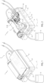
- the artificial diuresis device 1 further comprises a pump 12, in particular a peristaltic pump, for circulation of the organic liquid Lh through the disposable unit 3.
- the pump 12 comprises a head 8, which protrudes outside the body 21 of the machine 2, and an operation unit 9, which is inserted inside the cavity 22 of the machine 2 and, in use, rotates the head 8 around an axis of rotation Y.
- the head 8 of the peristaltic pump is configured to interact with the disposable unit 3, as will be illustrated in greater detail below, so as to cause circulation of the organic liquid Lh.
- the peristaltic pump 12 is of known type and schematically illustrated.
- the pump 12 is configured to obtain a pumping of 20-40 ml/minute.
- the flow rate of the pump 12 is certainly lower than that of the pumps commonly used in the fixed machines of known type for hemofiltration which is in the order of magnitude of 200 ml/minute.
- the disposable unit 3 further comprises:
- the tubes T1, T2, T3, T4 and T5 indicated above are of known type and schematically illustrated. In particular, they are made of flexible PVC and are disposable.
- the device 1 comprises one or more electric contacts (of known type and not illustrated) between the box 4 and the machine 2 for the passage of signals from one or more sensitive elements S, S1, S2, S3, S4 to the control unit 7.
- the device 1 is powered by a battery 14.
- the device 1 does not have to be connected to a fixed electric power supply network, allowing a patient H to move during the treatment.
- the device 1 further comprises a plurality of clamps Z of known type and schematically illustrated, each of which is configured to close the area of passage of a respective tube T so as to stop the passage of fluid.
- the device 1 comprises:
- the device 1 further comprises a needle free valve 15 applied to close the inlet I4 of the box 4.
- the valve 15 is of known type and is schematically illustrated.
- an operator can inject liquid, by means of a syringe, into the ultra-filtered channel C3 through the valve 15.
- the disposable unit 3 is completely filled with saline solution. This guarantees the absence of air inside the disposable unit 3 at the time of connection with the vascular access devices N1 and N2 and it is possible to immediately use the device 1 without carrying out a series of operations, generally known as priming operations, which necessarily have to be performed on board fixed hemofiltration machines.
- the tube T1 the inlet channel C1, the tube T2, the filtering unit 5, the tube T3, the outlet channel C2, the tube T4, the ultra-filtered channel C3 and the tube T5.
- the device 1 of the type described above is portable, therefore it can be used by a patient H in any place, at the same time allowing him/her to move.
- the device 1 of the type described above does not require the intervention of medical staff specialized in hemofiltration treatments in order to be applied to the patient.
- the device 1 of the type described above can be used also in any type of department and by medical staff not specialized in hemofiltration.
- the machine 2 further comprises a display 25 which dialogues with the control unit 7 and is configured to exchange data with the user.
- the display can be a graphic interface applied to the outside of the box-like body 21 of the machine 2.
- the display can be a graphic interface of a remote device such as, for example, the screen of a computer, tablet, smartphone and the like.
- the machine 2 and the disposable unit 3 are pre-arranged.
- the disposable unit 3 is hermetically sealed inside sterile packaging and is pre-filled with saline solution so as to guarantee the use thereof without the need to carry out a circuit preparation and filling phase, as with traditional devices.
- the disposable unit 3 once removed from its packaging, is applied to the box-like body 21 of the machine 2.
- the box 4 is coupled to the body 21 by means of the shape and/or interference couplings provided so as to guarantee that the disposable unit 3 assumes a predefined position during use.
- the tubes T are positioned in a predefined manner.
- the tube T2 is partially wound around the head 8 of the pump 12.
- the cartridge 35 is inserted in its housing if not already present.
- the collecting bag 6 is connected to the tube T5 if not already present.
- the vascular access devices N1 and N2 are applied to the patient H according to hemofiltration treatment methods known and not illustrated.
- the vascular access device N1 for drawing organic liquid Lh1 from the patient H is then connected to the inlet tube T1; analogously, the vascular access device N2 for the reinfusion of treated organic liquid Lh2 is connected to the outlet tube T2.
- the pump 12 When the ignition signal of the device 1 is given, for example via the display 25, the pump 12 is operated, causing the organic liquid Lh1 coming from the tube T1 to flow, pushing it into the filtering unit 5.
- the organic liquid Lh1 taken from the patient H enters the channel C1 of the disposable unit 3 and passes through the interaction area A1.
- the pressure measuring apparatus S1 detects the inlet pressure P1 of the incoming organic liquid Lh1.
- the inlet pressure value P1 serves to determine if there are obstructions or if the vascular access device N1 has become detached.
- the filtering unit 5 separates, in a known manner, the ultra-filtered liquid LU from the treated organic liquid Lh2.
- the treated organic liquid Lh2 is pushed into the outlet channel C2 and passes through the interaction area A2.
- the pressure measuring apparatus S2 detects the outlet pressure P2 of the treated organic liquid Lh2.
- the outlet pressure value P2 serves to determine if there are any obstructions or if the vascular access device N2 has become detached.
- the measuring apparatus S5 exchanges signals with the control unit 7 to stop operation of the device 1.
- the ultra-filtered liquid LU is pushed as it flows out of the filtering unit 5 through the outlet U4 into the ultra-filtered channel C3.
- the ultra-filtered liquid LU passes through the interaction areas A3 and A4.
- the flow rate is detected by means of the measuring apparatus S3 for detecting the flow and/or the presence of any blood traces by means of the blood measuring apparatus S4.
- the ultra-filtered liquid LU enters the collecting bag 6.
- control unit 7 detects abnormal functioning based on the signals detected by one or more of the measuring apparatuses S; S1, S2, S3, S4, S5 the control unit adjusts, in particular it slows down or stops, the operation unit 9 of the pump 12. In this way, advantageously, the treatment is stopped in a relatively short time.
- control unit 7 has a software to adjust the operation unit 9 according to the type of treatment to be carried out.
- the display 25 is configured to emit acoustic or visual alarms to draw the attention of the healthcare operators.
- the clamp Z3 is tightened so as to close the passage section of the tube T5.
- An operator can then inject treatment liquid Lt through the needle free valve 15 and inside the ultra-filtering channel C3 so as to obtain back-washing of the filtering unit 5.
- an operator with pre-loaded manual pumping means can introduce auxiliary liquid LA through the inlet I6 for any backflush.
- the device 1 of the type described above has reduced dimensions and is easy to apply.
- the device 1 Given the reduced flow rate of the organic liquid Lh through the device 1, it is possible to use the device 1 to carry out the treatments for longer periods of time than those carried out with traditional apparatuses.
- the device 1 of the type described above allows artificial diuresis to be obtained which is:
- the device 1 of the type described above is simple to apply thus allowing the performance of ultrafiltration processes also in situations where up to now these types of treatment were not applicable or could be obtained only by means of pharmaceutical treatment.
- the device 1 can be used to carry out the following treatments:
Landscapes
- Health & Medical Sciences (AREA)
- Heart & Thoracic Surgery (AREA)
- Vascular Medicine (AREA)
- Public Health (AREA)
- Biomedical Technology (AREA)
- Hematology (AREA)
- Life Sciences & Earth Sciences (AREA)
- Animal Behavior & Ethology (AREA)
- General Health & Medical Sciences (AREA)
- Engineering & Computer Science (AREA)
- Veterinary Medicine (AREA)
- Anesthesiology (AREA)
- Cardiology (AREA)
- Emergency Medicine (AREA)
- Physics & Mathematics (AREA)
- Fluid Mechanics (AREA)
- General Physics & Mathematics (AREA)
- Urology & Nephrology (AREA)
- External Artificial Organs (AREA)
- Prostheses (AREA)
- Transition And Organic Metals Composition Catalysts For Addition Polymerization (AREA)
- Materials For Medical Uses (AREA)
Claims (18)
- Dispositif de diurèse artificielle qui peut être porté par un patient (H) et comprend une machine réutilisable (2) et une unité jetable (3) ; caractérisé en ce que
ladite unité jetable (3) est scellée hermétiquement et est entièrement préremplie d'un liquide de traitement (Lt) ; dans lequel de l'air est absent à l'intérieur de l'unité jetable au moment du raccordement avec la machine réutilisable (2), de manière à permettre l'utilisation immédiate du dispositif de diurèse artificielle (1) sans exécuter d'opérations pour remplir l'unité jetable (3). - Dispositif de diurèse artificielle selon la revendication 1, dans lequel l'unité jetable (3) comprend un boîtier fonctionnel (4), qui comprend, à son tour, une pluralité d'appareils de mesure (S ; S1 ; S2 ; S3 ; S4 ; S5) ; dans lequel ladite machine (2) et ledit boîtier (4) sont configurés pour être couplés l'un à l'autre dans une configuration prédéfinie.
- Dispositif de diurèse artificielle selon la revendication 1, dans lequel le boîtier fonctionnel (4) présente :- une première entrée (I1) pour un liquide organique à traiter (Lh1) prélevé du patient (H) ;- une première sortie (U1) pour envoyer le liquide organique à traiter (Lh1) vers une unité de filtration (5) ;- un canal d'entrée (C1), qui raccorde la première entrée (I1) à la première sortie (U1) ;- une deuxième entrée (I2) pour un liquide organique traité (Lh2) provenant de ladite unité de filtration (5) ;- une deuxième sortie (U2) pour envoyer le liquide organique traité (Lh2) au patient (H) ;- un canal de sortie (C2), qui raccorde la deuxième entrée (I2) à la deuxième sortie (U2).
- Dispositif selon la revendication 3, dans lequel ledit boîtier (4) présente une première zone d'interaction (A1) long dudit canal d'entrée (C1) ; dans lequel ledit dispositif (1) comprend un premier appareil de mesure (S1), qui détecte, lors de l'utilisation, la pression du liquide organique à traiter (Lh1) dans la première zone d'interaction (A1).
- Dispositif selon la revendication 4, dans lequel ledit boîtier (4) présente une deuxième zone d'interaction (A2) ; dans lequel le dispositif (1) comprend un deuxième appareil de mesure (S2), qui détecte, lors de l'utilisation, la pression du liquide organique traité (Lh2) dans la deuxième zone d'interaction (A2).
- Dispositif de diurèse artificielle selon l'une quelconque des revendications 3 à 5, dans lequel le boîtier (4) présente :- une troisième entrée (I3) pour un liquide ultra-filtré (LU) ;- une troisième sortie (U3) pour envoyer le liquide ultra-filtré (LU) à une poche de collecte ;- un canal ultra-filtré (C3), qui raccorde la troisième entrée (I3) à la troisième sortie (U3).
- Dispositif de diurèse artificielle selon la revendication 6, dans lequel le boîtier (4) présente une quatrième entrée (I4) pour injecter du liquide dans le canal ultra-filtré (C3).
- Dispositif selon la revendication 6 ou 7, dans lequel ledit boîtier (4) présente une troisième zone d'interaction (A3) pour l'interaction avec ladite machine (2) le long dudit canal ultra-filtré (C3) ; dans lequel le dispositif (1) comprend un troisième appareil de mesure (S3) pour détecter l'écoulement du liquide ultra-filtré (LU) dans la troisième zone d'interaction (A3).
- Dispositif selon l'une quelconque des revendications 6 à 8, dans lequel ledit boîtier (4) présente une quatrième zone d'interaction (A4) le long dudit canal ultra-filtré (C3) ; dans lequel ledit dispositif (1) comprend un quatrième appareil de mesure (S4) pour détecter des traces de sang dans le liquide ultra-filtré (LU).
- Dispositif selon les revendications 8 et 9, dans lequel la troisième zone d'interaction (A3) et la quatrième zone d'interaction (A4) coïncident.
- Dispositif selon la revendication 9 ou 10, dans lequel le troisième appareil de mesure (S3) et le quatrième appareil de mesure (S4) sont incorporés dans une unité jetable (35), qui ne peut être utilisée qu'une seule fois.
- Dispositif selon l'une quelconque des revendications 9 à 11, dans lequel ladite machine (2) comprend un élément réfléchissant (37), qui délimite latéralement une partie respective de la quatrième zone d'interaction (A4) et interagit avec ledit quatrième appareil de mesure (S4) de manière à délimiter une section de passage (Q) pour le liquide ultra-filtré (LU) et augmenter le contraste d'éventuelles traces de sang dans le liquide ultra-filtré (LU).
- Dispositif selon l'une quelconque des revendications 4 à 12, dans lequel ladite machine (2) comprend un corps (21) présentant une cavité interne (22), dans lequel un ou plusieurs appareils de mesure (S1, S2) sont logés à l'intérieur de la cavité interne (22) et interagissent, lors de l'utilisation, avec une partie respective de l'unité jetable (3) dans les zones d'interaction (A1, A2) respectives.
- Dispositif selon l'une quelconque des revendications 3 à 13 et comprenant un cinquième appareil de mesure (S5), qui est configuré pour détecter la présence de bulles à l'intérieur du liquide organique traité (Lh2) ; dans lequel ledit cinquième appareil de mesure (S5) est agencé dans la zone de ladite deuxième sortie (U2).
- Dispositif selon l'une quelconque des revendications 4 à 14 et comprenant une unité de commande (7) ; dans lequel un ou plusieurs appareils de mesure (S1, S2, S3, S4, S5) échangent des signaux avec ladite unité de commande (7) ; dans lequel ladite unité de commande (7) est configurée pour interrompre le fonctionnement du dispositif (1) et/ou émettre des signaux d'alarme sonores et/ou lumineux dans le cas où des valeurs non conformes à des paramètres prédéterminés sont détectées.
- Dispositif selon la revendication 15, dans lequel ladite machine (2) comprend une pompe péristaltique (12), dans lequel ladite unité de commande (7) ajuste le fonctionnement de la pompe (12) en fonction des signaux détectés par un ou plusieurs appareils de mesure (S1, S2, S3, S4, S5).
- Dispositif selon la revendication 15 ou 16 et comprenant une interface (25), en particulier un écran, pour échanger des données de paramétrage et/ou des paramètres de fonctionnement et/ou des signaux d'alarme avec l'extérieur ; dans lequel ladite interface (25) peut être intégrée dans la machine (2) et/ou dans un dispositif externe, tel qu'un ordinateur, une tablette, un téléphone intelligent ou analogue.
- Dispositif selon l'une quelconque des revendications 6 à 17, dans lequel ledit boîtier (4) est un corps indivisible unique ; dans lequel lesdits canaux (C1, C2, C3) sont obtenus à l'intérieur du corps dudit boîtier (4).
Priority Applications (1)
| Application Number | Priority Date | Filing Date | Title |
|---|---|---|---|
| SM20240529T SMT202400529T1 (it) | 2021-01-13 | 2022-01-13 | Dispositivo per diuresi artificiale |
Applications Claiming Priority (2)
| Application Number | Priority Date | Filing Date | Title |
|---|---|---|---|
| IT102021000000521A IT202100000521A1 (it) | 2021-01-13 | 2021-01-13 | Dispositivo per diuresi artificiale |
| PCT/IB2022/050263 WO2022153210A2 (fr) | 2021-01-13 | 2022-01-13 | Dispositif de diurèse artificielle |
Publications (2)
| Publication Number | Publication Date |
|---|---|
| EP4277675A2 EP4277675A2 (fr) | 2023-11-22 |
| EP4277675B1 true EP4277675B1 (fr) | 2024-11-13 |
Family
ID=75340071
Family Applications (2)
| Application Number | Title | Priority Date | Filing Date |
|---|---|---|---|
| EP22705874.0A Active EP4277675B1 (fr) | 2021-01-13 | 2022-01-13 | Dispositif de diurèse artificielle |
| EP22151455.7A Pending EP4029541A1 (fr) | 2021-01-13 | 2022-01-13 | Appareil de mesure et dispositif de diurèse artificiel |
Family Applications After (1)
| Application Number | Title | Priority Date | Filing Date |
|---|---|---|---|
| EP22151455.7A Pending EP4029541A1 (fr) | 2021-01-13 | 2022-01-13 | Appareil de mesure et dispositif de diurèse artificiel |
Country Status (9)
| Country | Link |
|---|---|
| US (1) | US20240066200A1 (fr) |
| EP (2) | EP4277675B1 (fr) |
| JP (1) | JP2024502659A (fr) |
| CN (1) | CN117120120A (fr) |
| DK (1) | DK4277675T3 (fr) |
| ES (1) | ES3001141T3 (fr) |
| IT (1) | IT202100000521A1 (fr) |
| SM (1) | SMT202400529T1 (fr) |
| WO (1) | WO2022153210A2 (fr) |
Family Cites Families (11)
| Publication number | Priority date | Publication date | Assignee | Title |
|---|---|---|---|---|
| US4083777A (en) * | 1976-09-07 | 1978-04-11 | Union Carbide Corporation | Portable hemodialysis system |
| US8376978B2 (en) * | 2007-02-09 | 2013-02-19 | Baxter International Inc. | Optical access disconnection systems and methods |
| KR100827496B1 (ko) * | 2007-03-23 | 2008-05-06 | (주) 비에이치케이 | 슬라이드형 혈액여과장치 |
| MX338465B (es) * | 2008-08-27 | 2016-04-15 | Deka Products Lp | Arquitectura de control y metodos para sistemas de tratamiento de la sangre. |
| IT1402059B1 (it) * | 2010-09-29 | 2013-08-28 | Rand Srl | Sistema indossabile per eseguire terapie depurative di fluidi organici con l'impiego di circuiti extracorporei |
| DE102012009043A1 (de) * | 2012-05-04 | 2013-11-07 | Fresenius Medical Care Deutschland Gmbh | Bilanziervorrichtung, Dialysegerät, extrakorporaler Kreislauf und Verfahren zur Bilanzierung von Flüssigkeiten mit einer Flussmesszelle |
| JP5737477B2 (ja) * | 2012-07-05 | 2015-06-17 | 株式会社村田製作所 | 流量計、透析機、薬液注入装置 |
| ITBO20130024A1 (it) * | 2013-01-21 | 2014-07-22 | Medica S P A | Flussimetro differenziale per la misura del calo ponderale in trattamenti di emodialisi |
| DE102015010316A1 (de) * | 2015-08-06 | 2017-02-09 | Fresenius Medical Care Deutschland Gmbh | Portable Ultrafiltrationseinheit und Vorrichtung zur Versorgung der Ultrafiltrationseinheit mit Dialysierflüssigkeit |
| US10532145B2 (en) * | 2015-12-21 | 2020-01-14 | Fresenius Medical Care Holdings, Inc. | Modular blood treatment systems, units, and methods |
| IT201800005288A1 (it) | 2018-05-11 | 2019-11-11 | Macchina per emodialisi provvista di un sistema di misura della portata di un liquido e relativo metodo di funzionamento |
-
2021
- 2021-01-13 IT IT102021000000521A patent/IT202100000521A1/it unknown
-
2022
- 2022-01-13 US US18/271,890 patent/US20240066200A1/en active Pending
- 2022-01-13 SM SM20240529T patent/SMT202400529T1/it unknown
- 2022-01-13 EP EP22705874.0A patent/EP4277675B1/fr active Active
- 2022-01-13 CN CN202280009909.6A patent/CN117120120A/zh active Pending
- 2022-01-13 WO PCT/IB2022/050263 patent/WO2022153210A2/fr not_active Ceased
- 2022-01-13 DK DK22705874.0T patent/DK4277675T3/da active
- 2022-01-13 JP JP2023542872A patent/JP2024502659A/ja active Pending
- 2022-01-13 EP EP22151455.7A patent/EP4029541A1/fr active Pending
- 2022-01-13 ES ES22705874T patent/ES3001141T3/es active Active
Also Published As
| Publication number | Publication date |
|---|---|
| IT202100000521A1 (it) | 2022-07-13 |
| CN117120120A (zh) | 2023-11-24 |
| SMT202400529T1 (it) | 2025-01-14 |
| JP2024502659A (ja) | 2024-01-22 |
| WO2022153210A2 (fr) | 2022-07-21 |
| EP4277675A2 (fr) | 2023-11-22 |
| ES3001141T3 (es) | 2025-03-04 |
| EP4029541A1 (fr) | 2022-07-20 |
| US20240066200A1 (en) | 2024-02-29 |
| WO2022153210A3 (fr) | 2022-08-25 |
| DK4277675T3 (da) | 2025-01-13 |
Similar Documents
| Publication | Publication Date | Title |
|---|---|---|
| EP1666078B1 (fr) | Système de traitment extracorporel de sang avec des pompes réversibles | |
| EP1331964B1 (fr) | Dispositif de regulation du debit d'un fluide corporel dans des traitements extracorporels | |
| USRE38869E1 (en) | Extracorporeal circuit for peripheral vein fluid removal | |
| US4828543A (en) | Extracorporeal circulation apparatus | |
| EP2334412B1 (fr) | Système et procédé d amorçage pour systèmes de dialyse | |
| US7410473B2 (en) | Blood pump having a disposable blood filter with integrated pressure sensors | |
| US4486189A (en) | Dual mode hemodialysis system | |
| CN105813665B (zh) | 用于调节和给出血液泵的泵速率的装置和方法 | |
| EP3079757B1 (fr) | Ensemble jetable avec unité de valve pour pré/post-perfusion | |
| US20080177216A1 (en) | Devices and methods for body fluid flow control in extracorporeal fluid treatment | |
| JPS59131358A (ja) | 血液透析装置 | |
| EP1368108A1 (fr) | Methode et appareil pour module d'hemodiafiltration | |
| EP4277675B1 (fr) | Dispositif de diurèse artificielle | |
| EP3733224B1 (fr) | Unité de base de dialyse et système de dialyse | |
| JPS6357067B2 (fr) | ||
| JPS6354392B2 (fr) | ||
| CN120053793B (zh) | 一种连续性血液净化装置 | |
| JP6953162B2 (ja) | 血液浄化器 | |
| WO2022133574A1 (fr) | Rein artificiel d'hémofiltration portable | |
| Bernard et al. | Levin | |
| WO2005014083A1 (fr) | Dialyseur extracorporel portatif | |
| HK1057869B (en) | Device for body fluid flow control in extracorporeal fluid treatments | |
| ITBO990010A1 (it) | Macchina per il drenaggio del liquido ascitico accumulato in una cavita' addominale . |
Legal Events
| Date | Code | Title | Description |
|---|---|---|---|
| STAA | Information on the status of an ep patent application or granted ep patent |
Free format text: STATUS: UNKNOWN |
|
| STAA | Information on the status of an ep patent application or granted ep patent |
Free format text: STATUS: THE INTERNATIONAL PUBLICATION HAS BEEN MADE |
|
| PUAI | Public reference made under article 153(3) epc to a published international application that has entered the european phase |
Free format text: ORIGINAL CODE: 0009012 |
|
| STAA | Information on the status of an ep patent application or granted ep patent |
Free format text: STATUS: REQUEST FOR EXAMINATION WAS MADE |
|
| 17P | Request for examination filed |
Effective date: 20230728 |
|
| AK | Designated contracting states |
Kind code of ref document: A2 Designated state(s): AL AT BE BG CH CY CZ DE DK EE ES FI FR GB GR HR HU IE IS IT LI LT LU LV MC MK MT NL NO PL PT RO RS SE SI SK SM TR |
|
| DAV | Request for validation of the european patent (deleted) | ||
| DAX | Request for extension of the european patent (deleted) | ||
| GRAP | Despatch of communication of intention to grant a patent |
Free format text: ORIGINAL CODE: EPIDOSNIGR1 |
|
| STAA | Information on the status of an ep patent application or granted ep patent |
Free format text: STATUS: GRANT OF PATENT IS INTENDED |
|
| RIC1 | Information provided on ipc code assigned before grant |
Ipc: G01F 1/69 20060101ALI20240516BHEP Ipc: G01F 1/684 20060101ALI20240516BHEP Ipc: A61M 1/34 20060101ALI20240516BHEP Ipc: A61M 1/36 20060101ALI20240516BHEP Ipc: A61M 1/16 20060101AFI20240516BHEP |
|
| INTG | Intention to grant announced |
Effective date: 20240607 |
|
| P01 | Opt-out of the competence of the unified patent court (upc) registered |
Free format text: CASE NUMBER: APP_48932/2024 Effective date: 20240827 |
|
| GRAS | Grant fee paid |
Free format text: ORIGINAL CODE: EPIDOSNIGR3 |
|
| GRAA | (expected) grant |
Free format text: ORIGINAL CODE: 0009210 |
|
| STAA | Information on the status of an ep patent application or granted ep patent |
Free format text: STATUS: THE PATENT HAS BEEN GRANTED |
|
| AK | Designated contracting states |
Kind code of ref document: B1 Designated state(s): AL AT BE BG CH CY CZ DE DK EE ES FI FR GB GR HR HU IE IS IT LI LT LU LV MC MK MT NL NO PL PT RO RS SE SI SK SM TR |
|
| REG | Reference to a national code |
Ref country code: GB Ref legal event code: FG4D |
|
| REG | Reference to a national code |
Ref country code: CH Ref legal event code: EP |
|
| REG | Reference to a national code |
Ref country code: IE Ref legal event code: FG4D |
|
| REG | Reference to a national code |
Ref country code: DE Ref legal event code: R096 Ref document number: 602022007722 Country of ref document: DE |
|
| REG | Reference to a national code |
Ref country code: DK Ref legal event code: T3 Effective date: 20250110 |
|
| REG | Reference to a national code |
Ref country code: NL Ref legal event code: FP |
|
| REG | Reference to a national code |
Ref country code: SE Ref legal event code: TRGR |
|
| REG | Reference to a national code |
Ref country code: ES Ref legal event code: FG2A Ref document number: 3001141 Country of ref document: ES Kind code of ref document: T3 Effective date: 20250304 |
|
| REG | Reference to a national code |
Ref country code: GR Ref legal event code: EP Ref document number: 20250400071 Country of ref document: GR Effective date: 20250211 |
|
| REG | Reference to a national code |
Ref country code: LT Ref legal event code: MG9D |
|
| PG25 | Lapsed in a contracting state [announced via postgrant information from national office to epo] |
Ref country code: PT Free format text: LAPSE BECAUSE OF FAILURE TO SUBMIT A TRANSLATION OF THE DESCRIPTION OR TO PAY THE FEE WITHIN THE PRESCRIBED TIME-LIMIT Effective date: 20250313 Ref country code: HR Free format text: LAPSE BECAUSE OF FAILURE TO SUBMIT A TRANSLATION OF THE DESCRIPTION OR TO PAY THE FEE WITHIN THE PRESCRIBED TIME-LIMIT Effective date: 20241113 Ref country code: IS Free format text: LAPSE BECAUSE OF FAILURE TO SUBMIT A TRANSLATION OF THE DESCRIPTION OR TO PAY THE FEE WITHIN THE PRESCRIBED TIME-LIMIT Effective date: 20250313 |
|
| PG25 | Lapsed in a contracting state [announced via postgrant information from national office to epo] |
Ref country code: FI Free format text: LAPSE BECAUSE OF FAILURE TO SUBMIT A TRANSLATION OF THE DESCRIPTION OR TO PAY THE FEE WITHIN THE PRESCRIBED TIME-LIMIT Effective date: 20241113 |
|
| PG25 | Lapsed in a contracting state [announced via postgrant information from national office to epo] |
Ref country code: BG Free format text: LAPSE BECAUSE OF FAILURE TO SUBMIT A TRANSLATION OF THE DESCRIPTION OR TO PAY THE FEE WITHIN THE PRESCRIBED TIME-LIMIT Effective date: 20241113 |
|
| PG25 | Lapsed in a contracting state [announced via postgrant information from national office to epo] |
Ref country code: LV Free format text: LAPSE BECAUSE OF FAILURE TO SUBMIT A TRANSLATION OF THE DESCRIPTION OR TO PAY THE FEE WITHIN THE PRESCRIBED TIME-LIMIT Effective date: 20241113 |
|
| PGFP | Annual fee paid to national office [announced via postgrant information from national office to epo] |
Ref country code: CH Payment date: 20250201 Year of fee payment: 4 Ref country code: GR Payment date: 20250121 Year of fee payment: 4 |
|
| PG25 | Lapsed in a contracting state [announced via postgrant information from national office to epo] |
Ref country code: PL Free format text: LAPSE BECAUSE OF FAILURE TO SUBMIT A TRANSLATION OF THE DESCRIPTION OR TO PAY THE FEE WITHIN THE PRESCRIBED TIME-LIMIT Effective date: 20241113 |
|
| PG25 | Lapsed in a contracting state [announced via postgrant information from national office to epo] |
Ref country code: RS Free format text: LAPSE BECAUSE OF FAILURE TO SUBMIT A TRANSLATION OF THE DESCRIPTION OR TO PAY THE FEE WITHIN THE PRESCRIBED TIME-LIMIT Effective date: 20250213 |
|
| PG25 | Lapsed in a contracting state [announced via postgrant information from national office to epo] |
Ref country code: EE Free format text: LAPSE BECAUSE OF FAILURE TO SUBMIT A TRANSLATION OF THE DESCRIPTION OR TO PAY THE FEE WITHIN THE PRESCRIBED TIME-LIMIT Effective date: 20241113 |
|
| PG25 | Lapsed in a contracting state [announced via postgrant information from national office to epo] |
Ref country code: RO Free format text: LAPSE BECAUSE OF FAILURE TO SUBMIT A TRANSLATION OF THE DESCRIPTION OR TO PAY THE FEE WITHIN THE PRESCRIBED TIME-LIMIT Effective date: 20241113 |
|
| PG25 | Lapsed in a contracting state [announced via postgrant information from national office to epo] |
Ref country code: SK Free format text: LAPSE BECAUSE OF FAILURE TO SUBMIT A TRANSLATION OF THE DESCRIPTION OR TO PAY THE FEE WITHIN THE PRESCRIBED TIME-LIMIT Effective date: 20241113 |
|
| REG | Reference to a national code |
Ref country code: DE Ref legal event code: R097 Ref document number: 602022007722 Country of ref document: DE |
|
| PG25 | Lapsed in a contracting state [announced via postgrant information from national office to epo] |
Ref country code: LU Free format text: LAPSE BECAUSE OF NON-PAYMENT OF DUE FEES Effective date: 20250113 Ref country code: MC Free format text: LAPSE BECAUSE OF FAILURE TO SUBMIT A TRANSLATION OF THE DESCRIPTION OR TO PAY THE FEE WITHIN THE PRESCRIBED TIME-LIMIT Effective date: 20241113 |
|
| PLBE | No opposition filed within time limit |
Free format text: ORIGINAL CODE: 0009261 |
|
| STAA | Information on the status of an ep patent application or granted ep patent |
Free format text: STATUS: NO OPPOSITION FILED WITHIN TIME LIMIT |
|
| 26N | No opposition filed |
Effective date: 20250814 |
|
| PGFP | Annual fee paid to national office [announced via postgrant information from national office to epo] |
Ref country code: DK Payment date: 20251223 Year of fee payment: 5 |
|
| PG25 | Lapsed in a contracting state [announced via postgrant information from national office to epo] |
Ref country code: IE Free format text: LAPSE BECAUSE OF NON-PAYMENT OF DUE FEES Effective date: 20250113 |
|
| PGFP | Annual fee paid to national office [announced via postgrant information from national office to epo] |
Ref country code: CZ Payment date: 20251230 Year of fee payment: 5 |
|
| REG | Reference to a national code |
Ref country code: CH Ref legal event code: U11 Free format text: ST27 STATUS EVENT CODE: U-0-0-U10-U11 (AS PROVIDED BY THE NATIONAL OFFICE) Effective date: 20260201 |
|
| REG | Reference to a national code |
Ref country code: AT Ref legal event code: UEP Ref document number: 1741178 Country of ref document: AT Kind code of ref document: T Effective date: 20241113 |
|
| PGFP | Annual fee paid to national office [announced via postgrant information from national office to epo] |
Ref country code: NL Payment date: 20260122 Year of fee payment: 5 |
|
| PGFP | Annual fee paid to national office [announced via postgrant information from national office to epo] |
Ref country code: SM Payment date: 20260126 Year of fee payment: 5 |
|
| PGFP | Annual fee paid to national office [announced via postgrant information from national office to epo] |
Ref country code: SE Payment date: 20260126 Year of fee payment: 5 |
|
| PGFP | Annual fee paid to national office [announced via postgrant information from national office to epo] |
Ref country code: GB Payment date: 20260126 Year of fee payment: 5 |
|
| PGFP | Annual fee paid to national office [announced via postgrant information from national office to epo] |
Ref country code: ES Payment date: 20260210 Year of fee payment: 5 |
|
| PGFP | Annual fee paid to national office [announced via postgrant information from national office to epo] |
Ref country code: NO Payment date: 20260120 Year of fee payment: 5 Ref country code: DE Payment date: 20260127 Year of fee payment: 5 |
|
| PGFP | Annual fee paid to national office [announced via postgrant information from national office to epo] |
Ref country code: AT Payment date: 20260301 Year of fee payment: 5 |
|
| PGFP | Annual fee paid to national office [announced via postgrant information from national office to epo] |
Ref country code: BE Payment date: 20260123 Year of fee payment: 5 Ref country code: IT Payment date: 20260105 Year of fee payment: 5 |
|
| PGFP | Annual fee paid to national office [announced via postgrant information from national office to epo] |
Ref country code: FR Payment date: 20260126 Year of fee payment: 5 |