EP4277728B1 - Verfahren zur aufbereitung von distickstoffmonoxid-enthaltendem abgasstrom - Google Patents
Verfahren zur aufbereitung von distickstoffmonoxid-enthaltendem abgasstrom Download PDFInfo
- Publication number
- EP4277728B1 EP4277728B1 EP22700017.1A EP22700017A EP4277728B1 EP 4277728 B1 EP4277728 B1 EP 4277728B1 EP 22700017 A EP22700017 A EP 22700017A EP 4277728 B1 EP4277728 B1 EP 4277728B1
- Authority
- EP
- European Patent Office
- Prior art keywords
- gas stream
- temperature
- decomposition unit
- gas
- nitrous oxide
- Prior art date
- Legal status (The legal status is an assumption and is not a legal conclusion. Google has not performed a legal analysis and makes no representation as to the accuracy of the status listed.)
- Active
Links
Images
Classifications
-
- B—PERFORMING OPERATIONS; TRANSPORTING
- B01—PHYSICAL OR CHEMICAL PROCESSES OR APPARATUS IN GENERAL
- B01D—SEPARATION
- B01D53/00—Separation of gases or vapours; Recovering vapours of volatile solvents from gases; Chemical or biological purification of waste gases, e.g. engine exhaust gases, smoke, fumes, flue gases, aerosols
- B01D53/34—Chemical or biological purification of waste gases
- B01D53/343—Heat recovery
-
- B—PERFORMING OPERATIONS; TRANSPORTING
- B01—PHYSICAL OR CHEMICAL PROCESSES OR APPARATUS IN GENERAL
- B01D—SEPARATION
- B01D53/00—Separation of gases or vapours; Recovering vapours of volatile solvents from gases; Chemical or biological purification of waste gases, e.g. engine exhaust gases, smoke, fumes, flue gases, aerosols
- B01D53/34—Chemical or biological purification of waste gases
- B01D53/74—General processes for purification of waste gases; Apparatus or devices specially adapted therefor
- B01D53/86—Catalytic processes
- B01D53/8621—Removing nitrogen compounds
- B01D53/8625—Nitrogen oxides
-
- B—PERFORMING OPERATIONS; TRANSPORTING
- B01—PHYSICAL OR CHEMICAL PROCESSES OR APPARATUS IN GENERAL
- B01D—SEPARATION
- B01D53/00—Separation of gases or vapours; Recovering vapours of volatile solvents from gases; Chemical or biological purification of waste gases, e.g. engine exhaust gases, smoke, fumes, flue gases, aerosols
- B01D53/34—Chemical or biological purification of waste gases
- B01D53/74—General processes for purification of waste gases; Apparatus or devices specially adapted therefor
- B01D53/86—Catalytic processes
- B01D53/8696—Controlling the catalytic process
-
- C—CHEMISTRY; METALLURGY
- C07—ORGANIC CHEMISTRY
- C07C—ACYCLIC OR CARBOCYCLIC COMPOUNDS
- C07C51/00—Preparation of carboxylic acids or their salts, halides or anhydrides
- C07C51/16—Preparation of carboxylic acids or their salts, halides or anhydrides by oxidation
- C07C51/27—Preparation of carboxylic acids or their salts, halides or anhydrides by oxidation with oxides of nitrogen or nitrogen-containing mineral acids
- C07C51/275—Preparation of carboxylic acids or their salts, halides or anhydrides by oxidation with oxides of nitrogen or nitrogen-containing mineral acids of hydrocarbyl groups
-
- C—CHEMISTRY; METALLURGY
- C07—ORGANIC CHEMISTRY
- C07C—ACYCLIC OR CARBOCYCLIC COMPOUNDS
- C07C51/00—Preparation of carboxylic acids or their salts, halides or anhydrides
- C07C51/42—Separation; Purification; Stabilisation; Use of additives
- C07C51/43—Separation; Purification; Stabilisation; Use of additives by change of the physical state, e.g. crystallisation
-
- B—PERFORMING OPERATIONS; TRANSPORTING
- B01—PHYSICAL OR CHEMICAL PROCESSES OR APPARATUS IN GENERAL
- B01D—SEPARATION
- B01D2257/00—Components to be removed
- B01D2257/40—Nitrogen compounds
- B01D2257/402—Dinitrogen oxide
-
- Y—GENERAL TAGGING OF NEW TECHNOLOGICAL DEVELOPMENTS; GENERAL TAGGING OF CROSS-SECTIONAL TECHNOLOGIES SPANNING OVER SEVERAL SECTIONS OF THE IPC; TECHNICAL SUBJECTS COVERED BY FORMER USPC CROSS-REFERENCE ART COLLECTIONS [XRACs] AND DIGESTS
- Y02—TECHNOLOGIES OR APPLICATIONS FOR MITIGATION OR ADAPTATION AGAINST CLIMATE CHANGE
- Y02C—CAPTURE, STORAGE, SEQUESTRATION OR DISPOSAL OF GREENHOUSE GASES [GHG]
- Y02C20/00—Capture or disposal of greenhouse gases
- Y02C20/10—Capture or disposal of greenhouse gases of nitrous oxide (N2O)
Definitions
- the invention relates to a process for working-up a nitrous oxide comprising off-gas stream from a production process of adipic acid, the process comprising:
- nitric acid is added to a mixture of cyclohexanone and cyclohexanol.
- a reaction mixture comprising adipic acid and oxides of nitrogen, particularly nitrous oxide, nitrogen monoxide and nitrogen dioxide is obtained.
- the adipic acid usually is removed from the reaction mixture by crystallization and the oxides of nitrogen are stripped from the reaction mixture by blowing a gas, particularly air, through the reaction mixture.
- a gas particularly air
- the thus obtained off-gas stream comprising air, nitrogen dioxide and nitrous oxide is fed into a washing unit, usually a column, in which at least a part of the nitrogen dioxide is washed from the off-gas stream.
- the nitrogen dioxide may be reused for production of nitric acid which can be used for the production of adipic acid.
- the nitrous oxide can be used in other chemical processes, for example in an oxidation reaction for producing cyclododecanone and cyclopentanone.
- the nitrous oxide can be removed from the off-as by absorption/desorption processes like washing and desorption at different pressures with water.
- the remaining off-gas stream may be treated thermally or catalytically for decomposing the nitrous oxide, optionally by reduction with methane.
- the catalytic decomposition of the nitrous oxide usually is operated at a temperature in the range from 430°C to 800°C.
- concentration of nitrous oxide of the inlet stream into the decomposition unit which may be in the range from 6 to 20 vol-% may be reduced to a concentration in the outlet stream withdrawn from the decomposition unit in a range from 50 to 3000 vol-ppm.
- the temperature of the inlet stream for achieving the required decomposition rate depends inter alia on the inlet concentration and the catalyst age.
- the inlet temperature thereby usually is in the range from 430°C to 650°C with increasing inlet temperature on increasing catalyst age. If the desired concentration in the outlet stream cannot be achieved at a temperature of the inlet stream of 650°C, the catalyst must be changed.
- the challenge for decomposition of nitrous oxide from the off-gas from the production of adipic acid is the highly exothermic behavior of this reaction.
- Each percent of nitrous oxide in the off-gas stream creates an adiabatic temperature increase of 25°C.
- the temperature in the decomposition unit should remain below 800°C.
- the temperature should be as high as possible.
- a common limit is the design temperature of the inlet section in case of using standard chromium-nickel based steals, which usually is in a range from 550°C to 650°C.
- the optimum inlet temperature can be achieved by an optimum degree of heat recovery from the purified gas and/or additional preheating.
- the values for the recycling flow and for the inlet temperatures have to be adapted. To minimize emissions during this transition state, this should be done as fast as possible.
- the values are adapted on basis of the experience of the operators.
- the time scale for concentration propagation processes is in the range from 10 to 20 sec.
- the time scale for heat propagation processes is in the range from 10 to 20 min.
- EP-B 2 387 451 Processes and apparatus for removing nitrous oxide from a gas stream by catalytic decomposition are described for example in EP-B 2 387 451 , EP-B 1 413 349 , EP-B 2 387 450 , EP-B 2 165 756 or EP-B 2 548 629 .
- controllers for directing operation of an air pollution control system are known.
- a model predictive control is used.
- the pollutants which are to be removed from the off-gas particularly are sulfur dioxide and nitrogen oxides, namely nitrogen monoxide and nitrogen dioxide.
- CN 106 110 848 A discloses a process for the catalytic decomposition of nitrous oxide from the exhaust gas of the production of adipic acid, which is first washed by wet scrubbing, followed by heating in a first and a second heat exchanger, followed by further heating in an electric heater, the exhaust gas then enters the catalytic N2O decomposition reactor.
- This object is achieved by a process for working-up a nitrous oxide comprising off-gas stream from a production process of adipic acid, the process comprising:
- Nonlinear model predicted control as used in this invention is known to a skilled person and is described e.g. in L. Magni, D. M. Raimondo, F. Allgöwer, Nonlinear Model Predictive Control Towards New Challenging Applications, Springer Berlin Heidelberg, 2009 .
- the inventive control allows operating the process such that the amount of nitrous oxide in the purified gas can be kept in the order of 100 ppm or less.
- oxides of nitrogen means all oxides of nitrogen, including nitrous oxide and the so-called NO x , particularly nitrogen monoxide and nitrogen dioxide.
- NO x nitrogen monoxide and nitrogen dioxide.
- nitrogen oxides on the other hand does not include the nitrous oxide but only means NO x , particularly nitrogen monoxide and nitrogen dioxide.
- nitrogen oxides are absorbed from the off-gas stream in water by pressure absorption.
- an absorption column is used for absorbing the nitrogen oxides in water.
- the absorption column may be operated in counter current or co-current, preferably in counter current.
- the off-gas stream is fed into the absorption column at one end, preferably at the bottom and the water is fed at the other end, preferably the top of the absorption column.
- nitrogen dioxide is absorbed in water by formation of nitric acid and nitrogen monoxide.
- the nitrogen monoxide reacts with the oxygen in the off-gas stream by formation of nitrogen dioxide, which again is absorbed in water by the formation of nitric acid and nitrogen monoxide. This process repeats along the whole column so that at the exit of the column the amounts of nitrogen dioxide as well as nitrogen monoxide are reduced in the off-gas stream.
- the nitric acid comprising water is removed from the absorption column at the bottom.
- the absorption column preferably comprises 10 to 80 stages, more preferred 20 to 70 stages and particularly 40 to 60 stages.
- the temperature at which the absorption is carried out preferably is in a range from 5 to 70 °C, more preferred in a range from 10 to 60 °C and particularly in a range from 20 to 50°C.
- the absorption column preferably comprises internals. Suitable internals for example are packings like a packed bed or a structured packing. Further, the absorption column may comprise trays as internals. Particularly preferably, the internals in the absorption column are water-cooled trays.
- the nitrous oxide comprising off gas stream preferably is fed to the absorption column together with an additional gas mixture from ammonia combustion, comprising mainly nitrogen monoxide and nitrogen dioxide, water, oxygen, nitrogen, argon and carbon dioxide.
- nitrogen monoxide contained in the off-gas stream is oxidized to nitrogen dioxide before feeding the off-gas stream into the absorption column.
- nitrogen monoxide it is preferred to compress the off-gas stream to a pressure in a range from 1.2 to 3 bar(abs), more preferred in a range from 1.3 to 2.7 bar(abs) and particularly in a range from 1.5 to 2.5 bar(abs).
- the off-gas stream is cooled to a temperature in a range from 20 to 50°C, more preferred in a range from 25 to 45°C and particularly in a range from 30 to 40°C.
- the off-gas stream is compressed in a second step to a pressure in a range from 3 to 12 bar(abs), more preferred in a range from 4 to 11 bar(abs) and particularly in a range from 5 to 10 bar(abs).
- the thus compressed off-gas stream and additional air are passed through a residence-time reactor, wherein the ratio of the normalized volume flows of the compressed off-gas stream and additional air preferably is in a range from 1.5 to 3.5, more preferred in a range from 1.6 to 2.9 and particularly in a range from 1.8 to 2.5.
- the temperature inlet temperature of the off-gas stream into the residence-time reactor preferably is in a range from 120 to 300°C, more preferred in a range from 150 to 275°C and particularly in a range from 220 to 250°C
- the outlet temperature of the off-gas stream leaving the residence-time reactor preferably is in a range from 250 to 360°C, more preferred in a range from 270 to 350°C and particularly in a range from 280 to 340°C.
- the residence time of the off-gas stream in the residence-time reactor preferably is in a range from 10 to 60 sec, more preferred in a range from 15 to 50 sec and particularly in a range from 20 to 30 sec.
- the off-gas stream After passing the residence-time reactor, the off-gas stream is cooled to a temperature in the range from 10 to 50°C, more preferred in a range from 20 to 40°C and particularly in a range from 30 to 35°C.
- the off-gas stream is fed partially or completely into an N 2 O isolation in which nitrous oxide from at least a part of the off-gas stream is concentrated by a two-stage absorption/desorption process with water.
- N 2 O is absorbed in water in a first absorption column.
- the first absorption column is operated at a pressure in a range from 15 to 30 bar(abs), more preferred in a range from 17 to 28 bar(abs) and particularly in a range from 19 to 26 bar(abs) and a temperature in a range from 10 to 45°C, more preferred in a range from 20 to 42°C and particularly in a range from 30 to 35°C.
- the nitrous oxide is desorbed from the water in a first desorber which runs at a pressure in a range from 1 to 1.5 bar(abs), more preferred in a range from 1.05 to 1.3 bar(abs) and particularly in a range from 1.1 to 1.2 bar(abs) and a temperature in a range from 10 to 45°C, more preferred in a range from 20 to 42°C and particularly from 30 to 35°C.
- the resulting gas stream is fed into a second absorption column which runs at a pressure in a range from 15 to 30 bar(abs), more preferred in a range from 17 to 25 bar(abs) and particularly in a range from 19 to 23 bar(abs) and a temperature in a range from 10 to 45°C, more preferred in a range from 15 to 30°C and particularly in a range from 20 to 35°C.
- nitrous oxide is obtained which preferably is fed into a process for producing cyclododecanone and cyclopentanone.
- nitrous oxide in the off-gas stream from the pressure absorption and/or oxidation of nitrogen monoxide is absorbed in the two-stage absorption/desorption process.
- the remaining part preferably is split for being recycled into the off-gas stream comprising the mixture of the off-gas from adipic acid production and optionally off-gas from ammonia combustion, before carrying out the oxidation reaction of nitrogen monoxide and for being fed to the decomposition process of nitrous oxide.
- the off-gas stream withdrawn from the two stage absorption/desorption process still contains 5 to 18 vol% nitrous oxide.
- nitrous oxide has greenhouse-gas factor of about 300, it is necessary to remove the nitrous oxide from the off-gas stream.
- the off-gas stream is heated to a temperature in a range from 100 to 300°C, more preferred in a range from 170 to 270°C and particularly in a range from 210 to 260°C and then fed into the N 2 O decomposition unit in (i).
- the pressure with which the off-gas stream is fed into the N 2 O decomposition unit is in a range from 5 to 10 bar(abs), more preferred in a range from 6 to 9.5 bar(abs) and particularly in a range from 7 to 9 bar(abs).
- the off-gas stream is heated in a tube bundle heat exchanger, a u-tube bundle heat exchanger or a spiral heat exchanger.
- a tube bundle heat exchanger is used for heating.
- the hot off-gas withdrawn from the residence time reactor is used.
- the off-gas stream fed into the N 2 O decomposition unit contains 3 to 25 vol-% nitrous oxide, more preferred 4 to 18 vol-% nitrous oxide and particularly 6 to 13 vol-% nitrous oxide.
- the off-gas stream fed into the N 2 O decomposition unit may comprise 1 to 12 vol-% oxygen, 0.5 to 5 vol-% carbon dioxide, 0 to 0.3 vol-% carbon monoxide, 0.2 to 0.8 vol-% noble gases, particularly argon, 0.1 to 2 vol-% water, and 200 to 5000 vol-ppm nitrogen oxides, more preferred 1.5 to 6 vol-% oxygen, 0.7 to 3.5 vol-% carbon dioxide, 0 to 0.25 vol-% carbon monoxide, 0.3 to 0.6 vol-% noble gases, particularly argon, more preferred 0.2 to 1.3 vol-% water and 300 to 3000 vol-ppm nitrogen oxides and particularly 2 to 4 vol-% oxygen, 1 to 2 vol-% carbon dioxide, 0 to 0.2 vol-% carbon monoxide, 0.2 to 0.5 vol-% noble gases, particularly argon, 0.3 to 1 vol-% water, and 500 to 1000 vol-ppm nitrogen oxides.
- the main component in the off-gas stream is nitrogen which is comprised in an amount from 55 to 95 vol-%, more preferred from 70 to 92 vol-% and particularly from 80 to 90 vol-%.
- the off-gas stream may contain further impurities which usually are in amount below 2 vol-%, more preferred below 1 vol-% and particularly below 0.5 vol-%.
- the volume flow fed into the N 2 O decomposition unit may be in a range from 5000 to 70000 Nm 3 /h, more preferred in a range from 7000 to 60000 Nm 3 /h and particularly in a range from 10000 to 50000 Nm 3 /h.
- the process is also possible to use the process in a process where smaller amounts of nitrous oxide off-gas occur, for example in a pilot plant or in a laboratory.
- the process is used in industrial scale.
- the catalyst loading of the the nitrous oxide comprising volume flow in normalized cubic meters per hour and per kg catalyst on the fixed bed is in the range from 0.5 to 10 Nm 3 /h/kg catalyst, more preferred in a range from 1.5 to 6.5 Nm 3 /h/kg catalyst and particularly in a range from 2 to 4 Nm 3 /h/kg catalyst.
- the N 2 O decomposition unit preferably comprises a regenerative heat exchanger in which the nitrous oxide comprising off-gas stream is preheated.
- the regenerative heat exchanger particularly preferably is a regenerative heat exchanger in which the off-gas stream fed into the N 2 O decomposition unit is heated by heat transfer from the gas leaving the N 2 O decomposition unit. This has the additional positive effect that the purified gas being withdrawn from the N 2 O decomposition unit is cooled and that energy consumption for heating and cooling can be reduced.
- the regenerative heat exchanger can be any heat exchanger which is suitable for transferring heat from one gas stream to another gas stream by indirect heat transfer. Suitable heat exchangers for example are u-tube bundle heat exchangers, tube bundle heat exchanger or spiral heat exchangers. Preferred is a tube bundle heat exchanger.
- the heat transfer in the regenerative heat exchanger is not sufficient to heat the off-gas stream to a predefined temperature with which the off-gas stream is fed into the fixed bed reactor, it is preferred to provide an additional heater.
- the additional heater if a regenerative heat exchanger is comprised, or the heater, if no regenerative heat exchanger is used, preferably is an electrical heater.
- Direct gas fired heater means that the off gas of the gas fired heater is added to the nitrous oxide comprising off-gas stream.
- Indirect gas fired heater means that the heating the off-gas of the gas fired heater is transferred to the nitrous oxide comprising off-gas stream by an additional heat exchanger.
- a direct gas fired heater is preferred.
- the predefined temperature to which the off-gas stream is heated before feeding the off-gas stream into the fixed bed reactor is in a range from 430 to 650°C, more preferred in a range from 450 to 550°C and particularly in a range from 480 to 520°C.
- the thus heated off-gas stream is then fed into the fixed bed reactor for decomposing the nitrous oxide into nitrogen and oxygen.
- the fixed bed contains a suitable catalyst for the decomposition of the nitrous oxide.
- Suitable catalysts particularly are catalysts based on copper oxide and zinc oxide as catalytic material.
- the catalyst comprises a mixture of 14 to 18 wt-% copper oxide and less than 20 wt% zinc oxide as catalytic active material on aluminum oxide and/or magnesium oxide as support material.
- the catalyst preferably is provided as extrudates with a length of 2 mm to 2 cm, preferably of 4 mm to 1 cm and with a diameter of 2 mm to 10 mm, preferably of 4 to 8 mm.
- the cross sectional shape of the catalyst preferably is a circular disc or a star, preferably a star.
- the reaction in the fixed bed reactor is carried out at a temperature in a range from 430 to 800°C, more preferred in a range from 450 to 750°C and particularly in a range from 520 to 700°C.
- the temperature in the fixed bed reactor should not exceed 800°C. This is achieved by the nonlinear model predictive control according to the invention.
- the purified gas withdrawn from the fixed bed reactor is fed into the regenerative heat exchanger and cooled by heat transfer to the off-gas stream fed into the N 2 O decomposition unit.
- Cooling preferably is carried out by heat transfer in at least one heat exchanger in which heat is transferred to a cooling medium, particularly water.
- a cooling medium particularly water.
- the water is evaporated and/or superheated by the indirect heat transfer from the purified gas withdrawn from the fixed bed reactor.
- Suitable heat exchangers for cooling the purified gas for example are tube bundle heat exchangers, u-tube bundle heat exchangers, or spiral heat exchangers or coils in the pathway of the off-gas.
- the concentration of nitrous oxide in the off-gas stream which is fed into the N 2 O decomposition unit and particularly which is fed into the fixed bed reactor should be below 13 vol-%, more preferred below 12 vol.-% and particularly below 11 vol-%. If the concentration of nitrous oxide in the off-gas stream is above these values, preferably a part of the purified gas withdrawn from the decomposition reactor is recycled into the N 2 O decomposition unit as recycle stream. The amount of the recycle stream is set such that the amount of N 2 O in the gas stream being fed into the fixed bed reactor remains below these concentration values.
- the recycle stream is established by a recycle blower.
- the amount of recycled purified gas depends on the rotational speed of the recycle blower and/or on the internal recirculation rate of the recycle blower. By changing the degree of internal recirculation between the pressure and inlet side of the recycle blower the effective recycle stream can be changed without changing the rotational speed of the recycle blower.
- the purified gas withdrawn from the N 2 O decomposition unit through a denitrification plant, a so called DeNox unit, in which the nitrogen oxides are reduced.
- the DeNox unit may be any DeNox unit known to a skilled person.
- reduction of the nitrogen oxides is carried out in the presence of a solid catalyst by adding urea or ammonia.
- the gas stream Due to the high pressure of the gas stream which is passed through the N 2 O decomposition unit and optionally through the DeNox unit, it is preferred to pass the gas stream through an expansion turbine before releasing the gas into the atmosphere.
- the pressure can be used for producing electric current or for example for driving a compressor or any other apparatus having rotating parts which shall be driven.
- the process is controlled by the nonlinear model predictive control.
- the nonlinear model predictive control is based on a reactor model of the fixed bed based on the equations of energy transport and species transport for nitrogen, oxygen and nitrous oxide.
- a the energy transport and species transport, bed inlet temperature, bed inlet volume flow, bed outlet temperature, temperatures along the bed, concentration of the off-gas stream fed into the N 2 O decomposition unit and outlet concentration of the purified gas are measured and used as parameters for the model.
- any numeric process can be used, for example finite difference method, finite element method or finite volume method. Particularly preferably, the finite volume method is used.
- the optimum inlet temperature and recycle flow are calculated as a function of time for a given horizon in time.
- the thus calculated values are used for a given time step of optimum inlet temperature and optimum recycle flow as reference variable for control.
- the given time horizon for prediction preferably is in a range from 10 to 90 min, more preferred in a range from 20 to 75 min, and particularly in a range from 30 to 60 min.
- the given time step for updating the calculations and providing a new set of values for the optimum inlet temperature and recycle flow preferably is in a range from 5 to 30 sec, more preferred in a range from 7 to 25 sec and particularly in a range from 10 to 20 sec. This means that by the nonlinear model predictive control the controlled values are optimized for the time horizon into the future and this optimization is repeated with each time step with a shifted time horizon and based on new initial conditions.
- step (c1) for setting the recycle stream and/or the inlet temperature into the fixed bed reactor, the degree of bypass of the regenerative heat exchanger and/or electrical heating power and the rotational speed of the recycle blower and/or degree of internal recirculation of the recycle blower are adapted as actors of conventional PID-control of inlet temperature and inlet flow into the fixed bed reactor, and the nonlinear model predictive control proposes only the optimum inlet temperature and the optimum recycle flow.
- step (c2) the optimum degree of by-pass of the regenerative heat exchanger, if a regenerative heat exchanger is used, and/or heating power for the additional heater as well as the rotational speed of the recycle blower and/or degree of internal recirculation of the recycle blower are calculated as a function of time by using the reactor model for a given horizon in time and the bypass of the regenerative heat exchanger and/or the heating power and the rotational speed of the recycle blower and/or degree of internal recirculation of the recycle blower are adapted as direct actors of the nonlinear model predictive control.
- step (d) After reaching the end point of a time step, the time horizon is shifted with the given time step in step (d). After shifting the time horizon, steps (a) to (d) are repeated.
- the nonlinear model predictive control has the target for optimization that a time-integrated N 2 O-emission rate during prediction horizon is minimized. This means that the total N 2 O-emission during prediction horizon is minimized.
- a further target for optimization is that within the prediction horizon the N 2 O-outlet concentration is as close as possible equal to a set-point of the control.
- "as close as possible” can be defined as, but is not limited to, minimizing the time integrated squared difference between set-point and process value of N 2 O-outlet concentration.
- a further preferred target is that this set-point is below 800 ppm, more preferred below 500 ppm, mostly preferred below 100 ppm, and particularly 0 ppm.
- Restrictions in the nonlinear model predictive control of the reactor are that the value for the recycle flow (iv) is larger than 0 and smaller than a maximum capacity of the recycle blower, that the gas inlet temperature into the fixed bed reactor is smaller than a set-point of safety circuit minus an offset and that the bed temperature and the bed outlet temperature are smaller than the set-point of safety circuit minus an offset and the bed temperature and the bed outlet temperature are smaller than the start temperature of catalyst sintering and deactivation.
- the set-points of the safety circuits result from design limits of the N 2 O decomposition unit.
- the selected offset between maximum bed temperature to the start temperature of catalyst sintering and deactivation or between maximum gas inlet temperature or bed temperature or bed outlet temperature to the set-point of safety circuits is selected to be between 100 and 3 K, preferably between 50 and 3 K, more preferably between 30 and 3 K and particularly between 20 and 3 K.
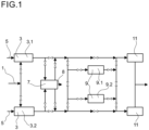
- a process for working-up a nitrous oxide comprising off-gas stream from a production process of adipic acid is shown schematically in figure 1 .
- a nitrous oxide comprising off-gas stream 1 is fed into a pressure absorption 3 for removing nitrogen oxides.
- the process comprises a first pressure absorption 3.1 and a second pressure absorption 3.2 for removing nitrogen oxides. This enables to continue the process by using one of the pressure absorptions 3.1, 3.2 for removing nitrogen oxides if the other pressure absorption 3.2, 3.1 is shut down, for example for maintenance purposes. Further, it is also possible to use both pressure absorptions 3.1, 3.2 for removing nitrogen oxides simultaneously.
- the nitrous oxide comprising off-gas stream 1 is compressed and cooled and passes a residence time in which nitrogen monoxide is converted into nitrogen dioxide. Subsequently, the gas stream is fed into an absorption column which comprises cooled trays, particularly trays which comprise cooling coils through which water flows. In the absorption column, a part of the nitrogen dioxide reacts with water forming nitric acid. This process preferably corresponds to a standard process for producing nitric acid.
- the off-gas of combustion of ammonia 5 also may be introduced into the pressure absorption 3. If off-gas of the combustion of ammonia 5 is fed into the pressure absorption 3, it is particularly preferred that the nitrous oxide comprising gas stream 1 from the production process of adipic acid and the off-gas of the combustion of ammonia 5 are mixed before the gas stream is compressed.
- the off-gas of the pressure absorption 3 is fed into an absorption/desorption process 7 in which nitrous oxide in the gas stream is removed partially by absorption in water and subsequent desorption processes, where a first absorption and desorption process is followed by at least one more absorption and desorption process.
- the absorption and desorption processes thereby are carried out at different pressures.
- the nitrous oxide 8 separated off and concentrated in the absorption/desorption process preferably is used in the production of cyclododecanone or cylco-pentanone.
- the nitrous oxide also may be used in any other process which uses nitrous oxide.
- the gas stream which is fed into the absorption/desorption process 7 particularly contains the residual nitrous oxide besides traces of nitrogen dioxide, after leaving the absorption/desorption process 7, the gas stream is fed into a N 2 O decomposition unit 9.
- one of the N 2 O decomposition units 9.1, 9.2 runs and the second N 2 O decomposition unit 9.2, 9.1 is in stand-by mode and can be used as redundancy in case of maintenance of one N 2 O decomposition unit for example during catalyst change.
- the N 2 O decomposition unit which is in stand-by can be used in case of a failure of the N 2 O decomposition unit which is in operation.
- the nitrous oxide is decomposed into nitrogen and oxygen.
- the gas stream leaving the N 2 O decomposition unit 9.1, 9.2 may still contain nitrogen oxides. Therefore, it is particularly preferred, as shown in figure 1 , to feed the gas stream after leaving the N 2 O decomposition unit 9.1, 9.2 into a DeNox unit 11 for reducing the amount of nitrogen oxides. After passing the DeNox unit 11, the gas stream is expanded and released into the atmosphere.
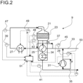
- a N 2 O decomposition unit is shown in figure 2 .
- Decomposition of nitrous oxide into nitrogen and oxygen is carried out at elevated temperatures, particularly at a temperature in the range between 430 to 800°C in a reactor 21 in presence of a catalyst.
- the reactor 21 may be for example a fixed bed reactor as shown in figure 2 .
- the fixed bed 23 contains a heterogeneous catalyst which promotes the decomposition reaction of nitrous oxide into nitrogen and oxygen.
- the decomposition reaction of nitrous oxide is exothermal.
- the gas stream For heating the gas stream containing the nitrous oxide, the gas stream preferably is fed into a regenerative heat exchanger 25 in which heat is transferred from the gas stream leaving the reactor 21 to the gas stream entering the N 2 O decomposition unit 9.
- a regenerative heat exchanger 25 By this internal heat transfer it is possible to reduce the energy which must be supplied to the process.
- the gas stream is fed into a heater 27.
- the heater may be any type of heater in which the gas can be heated to the temperature with which the gas stream is fed into the reactor 21.
- the heater 27 is an electrical heater.
- the nitrous oxide is decomposed forming oxygen and nitrogen.
- the gas stream obtained by the reaction then is fed into the regenerative heat exchanger 25 for heating the gas stream fed into the N 2 O decomposition unit 9.
- the off-gas withdrawn from the regenerative heat exchanger 25 may be further cooled in at least one additional heat exchanger 34.
- the additional heat exchanger 34 preferably is a heat exchanger for producing steam by evaporation of water or for superheating water.
- the off-gas withdrawn from the additional heat exchanger 34 can be fed into the DeNox unit 11 or released into the atmosphere. If multiple additional heat exchangers are used, the off-gas is first cooled in a heat exchanger, where saturated steam is superheated and is then cooled in a further heat exchanger where water is evaporated.
- a recycle line 29 with a recycle blower 31 is provided, the recycle line 29 connecting a feed line 33 by which the gas stream is fed into the N 2 O decomposition unit 9 and an exit line 35 by which the gas is withdrawn from the N 2 O decomposition unit 9.
- N 2 O decomposition unit 9 For controlling the N 2 O decomposition unit 9 using the nonlinear model predictive control, several process data must be measured. Further it is necessary to control the compressor 31 to set the amount of gas recycled into the gas stream fed into the N 2 O decomposition unit 9 and to control the heater 27 to heat the gas stream fed into the reactor to a predefined temperature. Further, for setting the temperature of the gas stream fed into the reactor 21 a bypass 37 may be provided, bypassing the regenerative heat exchanger 25.
- the bypass 37 may be closed so that the whole gas stream flows through the regenerative heat exchanger 25 or the bypass 37 is open and the feed line into the regenerative heat exchanger 25 is closed so that the whole gas stream flows through the bypass 37 or in a third alternative, the gas stream is split and a part flows through the regenerative heat exchanger 25 and a part through the bypass 37.
- a first temperature indicator 39 is provided for measuring the temperature of the gas stream after being heated in the heater 27 and a second temperature indicator 41 for measuring the temperature of the gas stream being withdrawn from the reactor 21 after having passed the regenerative heat exchanger 25 and the at least one additional heat exchanger 34.
- a third temperature indicator 43 the temperature in the reactor 21 after the fixed bed 23 is measured.
- the concentration of nitrous oxide in the gas stream is measured by a suitable quality indicator 45 and the flow rate of the gas stream fed into the reactor 21 by a flowmeter 47.
- a fourth temperature indicator 48 is used for measuring the temperature in the fixed bed 23 and by using a second quality indicator 50, the concentration of the nitrous oxide in the off-gas which flows through the exit line 35 is measured.
- Temperature measuring in the fixed bed is done with at least one temperature indicator 48.
- the temperature along the flow direction of the gas is not constant, it is preferred that 2 to 12 temperature indicators, and more preferably 3 to 10 temperature indicators which are arranged in succession in flow direction of the gas are used for measuring the temperature in the fixed bed 23.
- an optimum inlet temperature is calculated which is submitted to a temperature controller 49, which sets the amount of the gas stream flowing through the bypass 37 and/or for the power of the heater 27 to control the temperature of the gas fed into the reactor 21. Further, the nonlinear model predictive control may submit an optimum value of the amount of the gas stream which is recycled through the recycle line 29 to the flow controller 53, which sets the rotational speed and/or degree of internal recirculation of the recycle blower 31 to control the gas stream which is recycled through the recycle line 29.
- the data which are used for the nonlinear model predictive control are submitted to a data processing unit 51.
- the activity of the fixed bed 23 is calculated using an extended Kalman-Filter. Further, an optimum inlet temperature and a recycle flow are calculated by nonlinear model predictive control as a function of time by using a reactor model of the fixed bed reactor which is based on equations of energy transport and species transport for nitrogen, oxygen and nitrous oxide for a given horizon in time. The calculated values for a given time step of optimum inlet temperature and optimum recycle flow are used as reference variables for controlling the temperature by temperature controller 49 and the recycle stream which is recycled into the stream being fed into the N 2 O decomposition unit 9 via bypass 29 using a flow controller 53.
- the nonlinear model predictive control based on the reactor model is adapted such that either a degree of bypass of the regenerative heat exchanger and/or heating power of the heater and optionally the rotational speed of the recycle blower and/or degree of internal recirculation of the recycle blower are adapted as actors of conventional PID-control of inlet temperature of the fixed bed and optionally of the amount of the recycle flow, and the nonlinear model predictive control proposes only the optimum inlet temperature and recycle flow; or an optimum degree of bypass of the regenerative heat exchanger and/or heating power of the heater and optionally the rotational speed of the recycle blower and/or degree of internal recirculation of the recycle blower as function of time is calculated by using the nonlinear model predictive control algorithm which is based on the reactor model for given horizon in time and the degree of bypass of the regenerative heat exchanger and/or heating power and optionally the rotational speed of the recycle blower and/or degree of internal recirculation of the recycle blower is adapted as direct actors of the nonlinear
- the horizon in time is shifted with a given time step and subsequently, all measurements and calculations are repeated for the new horizon in time.
Landscapes
- Chemical & Material Sciences (AREA)
- Engineering & Computer Science (AREA)
- Environmental & Geological Engineering (AREA)
- Oil, Petroleum & Natural Gas (AREA)
- Organic Chemistry (AREA)
- General Chemical & Material Sciences (AREA)
- Analytical Chemistry (AREA)
- Biomedical Technology (AREA)
- Chemical Kinetics & Catalysis (AREA)
- Health & Medical Sciences (AREA)
- Crystallography & Structural Chemistry (AREA)
- Exhaust Gas Treatment By Means Of Catalyst (AREA)
- Treating Waste Gases (AREA)
Claims (11)
- Verfahren zur Aufarbeitung eines Distickstoffoxidumfassenden Abgasstroms aus einem Verfahren zur Herstellung von Adipinsäure, wobei das Verfahren umfasst:(i) Einspeisen des Abgasstroms in eine N2O-Zersetzungseinheit (9) mit einem Druck zwischen 5 und 10 bar(abs) und einer Temperatur zwischen 100 und 300 °C;(ii) Erhitzen des Abgasstroms auf eine Temperatur in dem Bereich von 430 bis 650 °C in einem regenerativen Wärmetauscher (25) und/oder einem Heizer (27);(iii) Zersetzen des im Abgasstrom enthaltenen Distickstoffoxids zu Stickstoff und Sauerstoff in einem Festbettreaktor (21) der N2O-Zersetzungseinheit (9) bei einer Temperatur in dem Bereich von 430 bis 800 °C, um ein gereinigtes Gas zu erhalten;(iv) gegebenenfalls Rückführen eines Teils des gereinigten Gases in die N2O-Zersetzungseinheit (9);wobei
zum Steuern der N2O-Zersetzungseinheit (9) eine prädiktive Steuerung mit nichtlinearem Modell verwendet wird, die auf der Grundlage eines Reaktormodell des Festbettreaktors auf der Grundlage von Gleichungen von Energietransport und Speziestransport für Stickstoff, Sauerstoff und N2O steht, wobei die prädiktive Steuerung mit nichtlinearem Modell umfasst:(a) Messen einer Betteinlasstemperatur, eines Betteinlassvolumenstroms, einer Bettauslasstemperatur, von Temperaturen entlang des Festbetts, Einlasskonzentrationen des in die N2O-Zersetzungseinheit eingespeisten Abgasstroms und Auslasskonzentrationen des gereinigten Gases als Parameter für das Modell;(b) Berechnen der Bettaktivität unter Verwendung eines erweiterten Kalman-Filters;(c) Berechnen einer optimalen Einlasstemperatur und gegebenenfalls eines Rückführflusses als Funktion der Zeit durch eine prädiktive Steuerung mit nichtlinearem Modell auf der Grundlage des Reaktormodells für einen gegebenen Zeithorizont und Verwendung berechneter Werte für einen gegebenen Zeitschritt mit optimaler Einlasstemperatur und optimalem Rückführfluss als Referenzvariable zur Steuerung, wobei(c1) ein Bypassgrad des regenerativen Wärmetauschers und/oder die Heizleistung des Heizers und die Drehzahl eines Rückführgebläses und/oder der interne Rezirkulationsgrad des Rückführgebläses als Akteure von herkömmlicher PID-Steuerung der Betteinlasstemperatur und des Rückführstroms angepasst werden und die prädiktive Steuerung mit nichtlinearem Modell auf der Grundlage des Reaktormodells nur die/den optimale(n) Einlasstemperatur und Rückführstrom vorschlägt;
oder(c2) Berechnen eines optimalen Bypassgrads des regenerativen Wärmetauschers und/oder der Heizleistung des Heizers und der Drehzahl eines Rückführgebläses und/oder des internen Rezirkulationsgrads des Rückführgebläses als Funktion der Zeit unter Verwendung des Reaktormodells für einen gegebenen Zeithorizont und Anpassung des Bypassgrads des regenerativen Wärmetauschers und/oder der Heizleistung und gegebenenfalls der Drehzahl eines Rückführgebläses und/oder des internen Rezirkulationsgrads des Rückführgebläses als direkte Akteure der prädiktiven Steuerung mit nichtlinearem Modell auf der Grundlage des Reaktormodells;(d) Verschieben des Zeithorizonts mit einem gegebenen Zeitschritt;(e) Wiederholen der Schritte (a) bis (d). - Verfahren nach Anspruch 1, dadurch gekennzeichnet, dass die prädiktive Steuerung mit nichtlinearem Modell das Ziel zur Optimierung, dass eine zeitintegrierte N2O-Emissionsrate während des Vorhersagehorizonts minimiert wird, aufweist.
- Verfahren nach Anspruch 1 oder 2, dadurch gekennzeichnet, dass die N2O-Auslasskonzentration möglichst nahe an einem Sollwert der Steuerung liegt.
- Verfahren nach einem der Ansprüche 1 bis 3, dadurch gekennzeichnet, dass der Wert für den Rückführstrom (iv) ≥ 0 und ≤ einer Höchstkapazität des Rückführgebläses beträgt, die Gaseinlasstemperatur in den Festbettreaktor ≤ eines Sicherheitsschaltung-Sollwerts abzüglich einer Regelabweichung beträgt und die Betttemperatur und die Bettauslasstemperatur ≤ des Sicherheitsschaltung-Sollwerts abzüglich einer Regelabweichung betragen und die Betttemperatur und die Bettauslasstemperatur ≤ der Starttemperatur von Katalysatorsinterung und - deaktivierung betragen, wobei die Sollwerte der Sicherheitsschaltung aus Grenzwerten der N2O-Zersetzungseinheit folgen.
- Verfahren nach Anspruch 4, dadurch gekennzeichnet, dass die Regelabweichung in einem Bereich von 3 bis 100 K liegt.
- Verfahren nach einem der Ansprüche 1 bis 5, dadurch gekennzeichnet, dass der Abgasstrom in dem regenerativen Wärmetauscher (25) durch Wärmeübergang von dem gereinigten Gas wenigstens teilweise erhitzt wird.
- Verfahren nach einem der Ansprüche 1 bis 6, dadurch gekennzeichnet, dass der in die N2O-Zersetzungseinheit eingespeiste Abgasstrom 200 bis 5000 Vol.-ppm NOX, 0,5 bis 5 Vol.-% CO2, 2 bis 12 Vol.-% O2, 0 bis 0,3 Vol.-% CO, 3 bis 25 Vol.-% N2O und 0,2 bis 0,8 Vol.-% Ar umfasst.
- Verfahren nach einem der Ansprüche 1 bis 7, dadurch gekennzeichnet, dass das gereinigte Gas durch eine DeNox-Einheit (11) zur Verringerung der NOX-Menge geleitet wird.
- Verfahren nach einem der Ansprüche 1 bis 8, dadurch gekennzeichnet, dass Distickstoffoxid aus dem Abgasstrom in Wasser durch Druckabsorption (7) absorbiert wird, bevor der Abgasstrom in die N2O-Zersetzungseinheit (9) eingespeist wird.
- Verfahren nach einem der Ansprüche 1 bis 9, dadurch gekennzeichnet, dass im Abgasstrom enthaltene Stickoxide durch Druckabsorption in Wasser entfernt werden, bevor der Abgasstrom in die N2O-Zersetzungseinheit (9) eingespeist wird.
- Verfahren nach einem der Ansprüche 1 bis 10, dadurch gekennzeichnet, dass der Teil des gereinigten Gases in die N2O-Zersetzungseinheit zurückgeführt wird, wenn die N2O-Konzentration in dem in die N2O-Zersetzungseinheit eingespeisten Abgasstrom über 11 Gew.-% liegt.
Applications Claiming Priority (2)
| Application Number | Priority Date | Filing Date | Title |
|---|---|---|---|
| EP21151410 | 2021-01-13 | ||
| PCT/EP2022/050139 WO2022152605A1 (en) | 2021-01-13 | 2022-01-05 | Process for working-up a nitrous oxide comprising off-gas stream |
Publications (2)
| Publication Number | Publication Date |
|---|---|
| EP4277728A1 EP4277728A1 (de) | 2023-11-22 |
| EP4277728B1 true EP4277728B1 (de) | 2025-01-29 |
Family
ID=74181044
Family Applications (1)
| Application Number | Title | Priority Date | Filing Date |
|---|---|---|---|
| EP22700017.1A Active EP4277728B1 (de) | 2021-01-13 | 2022-01-05 | Verfahren zur aufbereitung von distickstoffmonoxid-enthaltendem abgasstrom |
Country Status (6)
| Country | Link |
|---|---|
| US (1) | US20240216862A1 (de) |
| EP (1) | EP4277728B1 (de) |
| KR (1) | KR20230132508A (de) |
| CN (1) | CN116745021A (de) |
| CA (1) | CA3204884A1 (de) |
| WO (1) | WO2022152605A1 (de) |
Families Citing this family (2)
| Publication number | Priority date | Publication date | Assignee | Title |
|---|---|---|---|---|
| WO2026017476A1 (en) | 2024-07-17 | 2026-01-22 | Basf Se | Process for removing n2o from a gas stream |
| CN119680376B (zh) * | 2024-11-25 | 2026-03-24 | 北京工业大学 | 一种回收净化尾气及余热的己二酸尾气氮氧化物处理工艺 |
Family Cites Families (10)
| Publication number | Priority date | Publication date | Assignee | Title |
|---|---|---|---|---|
| JPH054027A (ja) * | 1991-06-28 | 1993-01-14 | Asahi Chem Ind Co Ltd | 排一酸化二窒素ガスの処理方法 |
| DE19533715A1 (de) * | 1995-09-12 | 1997-03-13 | Basf Ag | Verfahren zum Entfernen von Stickstoffoxiden aus einem diese enthaltenden Gasstrom |
| EP1413349B1 (de) | 2002-10-25 | 2006-03-29 | Radici Chimica Spa | Verfahren zur katalytischen Zersetzung von Distickstoffmonoxid (N2O) |
| US7117046B2 (en) | 2004-08-27 | 2006-10-03 | Alstom Technology Ltd. | Cascaded control of an average value of a process parameter to a desired value |
| US7522963B2 (en) | 2004-08-27 | 2009-04-21 | Alstom Technology Ltd | Optimized air pollution control |
| EP2165756B2 (de) | 2008-09-19 | 2016-06-01 | Linde AG | Verfahren zur Dekomposition von Distickstoffmonoxid in einem Gasstrom |
| DE102009037882A1 (de) | 2009-01-13 | 2010-07-15 | Linde Aktiengesellschaft | Vorrichtung und Verfahren zur Zersetzung von Lachgas in einem adiabaten Festbettreaktor |
| JP5541951B2 (ja) | 2010-03-19 | 2014-07-09 | メタウォーター株式会社 | 排ガス中のn2o除去装置およびn2o除去方法 |
| US9567875B2 (en) * | 2012-02-23 | 2017-02-14 | Showa Denko K.K. | Power generation apparatus, power generation method, decomposition-gas turbine and decomposition-gas boiler |
| CN106110848A (zh) * | 2016-07-13 | 2016-11-16 | 成都普瑞得科技有限公司 | 氮氧化物减排系统与氮氧化物减排的方法 |
-
2022
- 2022-01-05 US US18/271,877 patent/US20240216862A1/en active Pending
- 2022-01-05 CA CA3204884A patent/CA3204884A1/en active Pending
- 2022-01-05 CN CN202280009614.9A patent/CN116745021A/zh active Pending
- 2022-01-05 KR KR1020237027163A patent/KR20230132508A/ko active Pending
- 2022-01-05 WO PCT/EP2022/050139 patent/WO2022152605A1/en not_active Ceased
- 2022-01-05 EP EP22700017.1A patent/EP4277728B1/de active Active
Also Published As
| Publication number | Publication date |
|---|---|
| KR20230132508A (ko) | 2023-09-15 |
| CA3204884A1 (en) | 2022-07-21 |
| EP4277728A1 (de) | 2023-11-22 |
| CN116745021A (zh) | 2023-09-12 |
| WO2022152605A1 (en) | 2022-07-21 |
| US20240216862A1 (en) | 2024-07-04 |
Similar Documents
| Publication | Publication Date | Title |
|---|---|---|
| AU2007315318B2 (en) | Process and apparatus for the catalytic oxidation of SO2-Containing gases by means of oxygen | |
| US6056928A (en) | Method of removing nitrogen oxides from a gas flow | |
| US8060258B2 (en) | Multivariable process controller and methodology for controlling catalyzed chemical reaction to form phthalic anhydride and other functionalized aromatics | |
| EP4277728B1 (de) | Verfahren zur aufbereitung von distickstoffmonoxid-enthaltendem abgasstrom | |
| JP7814468B2 (ja) | 排ガス焼却炉の制御 | |
| US8951494B2 (en) | Process and apparatus for sulphuric acid production | |
| US20250282614A1 (en) | Process for cracking ammonia | |
| CA2845760A1 (en) | Improved nitric acid production | |
| DK2330075T3 (en) | METHOD OF PRODUCING SULFURIC ACID | |
| EP4277888B1 (de) | Verfahren zur zersetzung von distickstoffoxid aus einem gasstrom | |
| EP2099711B1 (de) | Verfahren zur herstellung von schwefelsäure | |
| EP0799794A1 (de) | Sauerstoffeinspritzung in der Produktion von Salpetersäure | |
| US5494650A (en) | Process for improving the sulphur yield of a complex for producing sulphur from a sour gas containing H2 S, the said complex comprising a sulphur plant and then an oxidation and hydrolysis unit followed by a purification unit | |
| US11407645B2 (en) | Method and apparatus for producing carbon dioxide | |
| RU2174946C1 (ru) | Способ производства азотной кислоты | |
| TW201113217A (en) | A process and a plant for producing sulphuric acid | |
| AU2013202363A1 (en) | Process and apparatus for the catalytic oxidation of SO2-containing gases by means of oxygen | |
| KR20250044010A (ko) | 일산화질소 제조 시스템 및 제조방법 |
Legal Events
| Date | Code | Title | Description |
|---|---|---|---|
| STAA | Information on the status of an ep patent application or granted ep patent |
Free format text: STATUS: UNKNOWN |
|
| STAA | Information on the status of an ep patent application or granted ep patent |
Free format text: STATUS: THE INTERNATIONAL PUBLICATION HAS BEEN MADE |
|
| PUAI | Public reference made under article 153(3) epc to a published international application that has entered the european phase |
Free format text: ORIGINAL CODE: 0009012 |
|
| STAA | Information on the status of an ep patent application or granted ep patent |
Free format text: STATUS: REQUEST FOR EXAMINATION WAS MADE |
|
| 17P | Request for examination filed |
Effective date: 20230814 |
|
| AK | Designated contracting states |
Kind code of ref document: A1 Designated state(s): AL AT BE BG CH CY CZ DE DK EE ES FI FR GB GR HR HU IE IS IT LI LT LU LV MC MK MT NL NO PL PT RO RS SE SI SK SM TR |
|
| DAV | Request for validation of the european patent (deleted) | ||
| DAX | Request for extension of the european patent (deleted) | ||
| GRAP | Despatch of communication of intention to grant a patent |
Free format text: ORIGINAL CODE: EPIDOSNIGR1 |
|
| STAA | Information on the status of an ep patent application or granted ep patent |
Free format text: STATUS: GRANT OF PATENT IS INTENDED |
|
| INTG | Intention to grant announced |
Effective date: 20240902 |
|
| GRAS | Grant fee paid |
Free format text: ORIGINAL CODE: EPIDOSNIGR3 |
|
| P01 | Opt-out of the competence of the unified patent court (upc) registered |
Free format text: CASE NUMBER: APP_61526/2024 Effective date: 20241118 |
|
| GRAA | (expected) grant |
Free format text: ORIGINAL CODE: 0009210 |
|
| STAA | Information on the status of an ep patent application or granted ep patent |
Free format text: STATUS: THE PATENT HAS BEEN GRANTED |
|
| AK | Designated contracting states |
Kind code of ref document: B1 Designated state(s): AL AT BE BG CH CY CZ DE DK EE ES FI FR GB GR HR HU IE IS IT LI LT LU LV MC MK MT NL NO PL PT RO RS SE SI SK SM TR |
|
| REG | Reference to a national code |
Ref country code: GB Ref legal event code: FG4D |
|
| REG | Reference to a national code |
Ref country code: CH Ref legal event code: EP |
|
| REG | Reference to a national code |
Ref country code: DE Ref legal event code: R096 Ref document number: 602022010127 Country of ref document: DE |
|
| REG | Reference to a national code |
Ref country code: IE Ref legal event code: FG4D |
|
| REG | Reference to a national code |
Ref country code: NL Ref legal event code: MP Effective date: 20250129 |
|
| PG25 | Lapsed in a contracting state [announced via postgrant information from national office to epo] |
Ref country code: NL Free format text: LAPSE BECAUSE OF FAILURE TO SUBMIT A TRANSLATION OF THE DESCRIPTION OR TO PAY THE FEE WITHIN THE PRESCRIBED TIME-LIMIT Effective date: 20250129 |
|
| PG25 | Lapsed in a contracting state [announced via postgrant information from national office to epo] |
Ref country code: RS Free format text: LAPSE BECAUSE OF FAILURE TO SUBMIT A TRANSLATION OF THE DESCRIPTION OR TO PAY THE FEE WITHIN THE PRESCRIBED TIME-LIMIT Effective date: 20250429 |
|
| PG25 | Lapsed in a contracting state [announced via postgrant information from national office to epo] |
Ref country code: FI Free format text: LAPSE BECAUSE OF FAILURE TO SUBMIT A TRANSLATION OF THE DESCRIPTION OR TO PAY THE FEE WITHIN THE PRESCRIBED TIME-LIMIT Effective date: 20250129 |
|
| PG25 | Lapsed in a contracting state [announced via postgrant information from national office to epo] |
Ref country code: PL Free format text: LAPSE BECAUSE OF FAILURE TO SUBMIT A TRANSLATION OF THE DESCRIPTION OR TO PAY THE FEE WITHIN THE PRESCRIBED TIME-LIMIT Effective date: 20250129 |
|
| PG25 | Lapsed in a contracting state [announced via postgrant information from national office to epo] |
Ref country code: ES Free format text: LAPSE BECAUSE OF FAILURE TO SUBMIT A TRANSLATION OF THE DESCRIPTION OR TO PAY THE FEE WITHIN THE PRESCRIBED TIME-LIMIT Effective date: 20250129 |
|
| REG | Reference to a national code |
Ref country code: LT Ref legal event code: MG9D |
|
| PG25 | Lapsed in a contracting state [announced via postgrant information from national office to epo] |
Ref country code: IS Free format text: LAPSE BECAUSE OF FAILURE TO SUBMIT A TRANSLATION OF THE DESCRIPTION OR TO PAY THE FEE WITHIN THE PRESCRIBED TIME-LIMIT Effective date: 20250529 Ref country code: NO Free format text: LAPSE BECAUSE OF FAILURE TO SUBMIT A TRANSLATION OF THE DESCRIPTION OR TO PAY THE FEE WITHIN THE PRESCRIBED TIME-LIMIT Effective date: 20250429 |
|
| REG | Reference to a national code |
Ref country code: AT Ref legal event code: MK05 Ref document number: 1762899 Country of ref document: AT Kind code of ref document: T Effective date: 20250129 |
|
| PG25 | Lapsed in a contracting state [announced via postgrant information from national office to epo] |
Ref country code: HR Free format text: LAPSE BECAUSE OF FAILURE TO SUBMIT A TRANSLATION OF THE DESCRIPTION OR TO PAY THE FEE WITHIN THE PRESCRIBED TIME-LIMIT Effective date: 20250129 |
|
| PG25 | Lapsed in a contracting state [announced via postgrant information from national office to epo] |
Ref country code: LV Free format text: LAPSE BECAUSE OF FAILURE TO SUBMIT A TRANSLATION OF THE DESCRIPTION OR TO PAY THE FEE WITHIN THE PRESCRIBED TIME-LIMIT Effective date: 20250129 Ref country code: PT Free format text: LAPSE BECAUSE OF FAILURE TO SUBMIT A TRANSLATION OF THE DESCRIPTION OR TO PAY THE FEE WITHIN THE PRESCRIBED TIME-LIMIT Effective date: 20250529 |
|
| PG25 | Lapsed in a contracting state [announced via postgrant information from national office to epo] |
Ref country code: BG Free format text: LAPSE BECAUSE OF FAILURE TO SUBMIT A TRANSLATION OF THE DESCRIPTION OR TO PAY THE FEE WITHIN THE PRESCRIBED TIME-LIMIT Effective date: 20250129 Ref country code: GR Free format text: LAPSE BECAUSE OF FAILURE TO SUBMIT A TRANSLATION OF THE DESCRIPTION OR TO PAY THE FEE WITHIN THE PRESCRIBED TIME-LIMIT Effective date: 20250430 |
|
| PG25 | Lapsed in a contracting state [announced via postgrant information from national office to epo] |
Ref country code: AT Free format text: LAPSE BECAUSE OF FAILURE TO SUBMIT A TRANSLATION OF THE DESCRIPTION OR TO PAY THE FEE WITHIN THE PRESCRIBED TIME-LIMIT Effective date: 20250129 |
|
| PG25 | Lapsed in a contracting state [announced via postgrant information from national office to epo] |
Ref country code: SE Free format text: LAPSE BECAUSE OF FAILURE TO SUBMIT A TRANSLATION OF THE DESCRIPTION OR TO PAY THE FEE WITHIN THE PRESCRIBED TIME-LIMIT Effective date: 20250129 |
|
| PG25 | Lapsed in a contracting state [announced via postgrant information from national office to epo] |
Ref country code: SM Free format text: LAPSE BECAUSE OF FAILURE TO SUBMIT A TRANSLATION OF THE DESCRIPTION OR TO PAY THE FEE WITHIN THE PRESCRIBED TIME-LIMIT Effective date: 20250129 |
|
| PG25 | Lapsed in a contracting state [announced via postgrant information from national office to epo] |
Ref country code: DK Free format text: LAPSE BECAUSE OF FAILURE TO SUBMIT A TRANSLATION OF THE DESCRIPTION OR TO PAY THE FEE WITHIN THE PRESCRIBED TIME-LIMIT Effective date: 20250129 |
|
| PG25 | Lapsed in a contracting state [announced via postgrant information from national office to epo] |
Ref country code: EE Free format text: LAPSE BECAUSE OF FAILURE TO SUBMIT A TRANSLATION OF THE DESCRIPTION OR TO PAY THE FEE WITHIN THE PRESCRIBED TIME-LIMIT Effective date: 20250129 Ref country code: CZ Free format text: LAPSE BECAUSE OF FAILURE TO SUBMIT A TRANSLATION OF THE DESCRIPTION OR TO PAY THE FEE WITHIN THE PRESCRIBED TIME-LIMIT Effective date: 20250129 |
|
| PG25 | Lapsed in a contracting state [announced via postgrant information from national office to epo] |
Ref country code: RO Free format text: LAPSE BECAUSE OF FAILURE TO SUBMIT A TRANSLATION OF THE DESCRIPTION OR TO PAY THE FEE WITHIN THE PRESCRIBED TIME-LIMIT Effective date: 20250129 |
|
| PG25 | Lapsed in a contracting state [announced via postgrant information from national office to epo] |
Ref country code: SK Free format text: LAPSE BECAUSE OF FAILURE TO SUBMIT A TRANSLATION OF THE DESCRIPTION OR TO PAY THE FEE WITHIN THE PRESCRIBED TIME-LIMIT Effective date: 20250129 |
|
| REG | Reference to a national code |
Ref country code: DE Ref legal event code: R097 Ref document number: 602022010127 Country of ref document: DE |
|
| PLBE | No opposition filed within time limit |
Free format text: ORIGINAL CODE: 0009261 |
|
| STAA | Information on the status of an ep patent application or granted ep patent |
Free format text: STATUS: NO OPPOSITION FILED WITHIN TIME LIMIT |
|
| 26N | No opposition filed |
Effective date: 20251030 |
|
| PGFP | Annual fee paid to national office [announced via postgrant information from national office to epo] |
Ref country code: DE Payment date: 20260127 Year of fee payment: 5 |
|
| PGFP | Annual fee paid to national office [announced via postgrant information from national office to epo] |
Ref country code: IT Payment date: 20260123 Year of fee payment: 5 |
|
| PGFP | Annual fee paid to national office [announced via postgrant information from national office to epo] |
Ref country code: FR Payment date: 20260126 Year of fee payment: 5 |