EP4279737A1 - Extracteur d'air doté d'une pompe à liquide - Google Patents
Extracteur d'air doté d'une pompe à liquide Download PDFInfo
- Publication number
- EP4279737A1 EP4279737A1 EP23174199.2A EP23174199A EP4279737A1 EP 4279737 A1 EP4279737 A1 EP 4279737A1 EP 23174199 A EP23174199 A EP 23174199A EP 4279737 A1 EP4279737 A1 EP 4279737A1
- Authority
- EP
- European Patent Office
- Prior art keywords
- air
- cavity
- liquid
- sub
- air extracting
- Prior art date
- Legal status (The legal status is an assumption and is not a legal conclusion. Google has not performed a legal analysis and makes no representation as to the accuracy of the status listed.)
- Granted
Links
Images




Classifications
-
- F—MECHANICAL ENGINEERING; LIGHTING; HEATING; WEAPONS; BLASTING
- F04—POSITIVE - DISPLACEMENT MACHINES FOR LIQUIDS; PUMPS FOR LIQUIDS OR ELASTIC FLUIDS
- F04C—ROTARY-PISTON, OR OSCILLATING-PISTON, POSITIVE-DISPLACEMENT MACHINES FOR LIQUIDS; ROTARY-PISTON, OR OSCILLATING-PISTON, POSITIVE-DISPLACEMENT PUMPS
- F04C27/00—Sealing arrangements in rotary-piston pumps specially adapted for elastic fluids
- F04C27/02—Liquid sealing for high-vacuum pumps or for compressors
-
- F—MECHANICAL ENGINEERING; LIGHTING; HEATING; WEAPONS; BLASTING
- F04—POSITIVE - DISPLACEMENT MACHINES FOR LIQUIDS; PUMPS FOR LIQUIDS OR ELASTIC FLUIDS
- F04D—NON-POSITIVE-DISPLACEMENT PUMPS
- F04D17/00—Radial-flow pumps, e.g. centrifugal pumps; Helico-centrifugal pumps
- F04D17/08—Centrifugal pumps
- F04D17/18—Centrifugal pumps characterised by use of centrifugal force of liquids entrained in pumps
-
- F—MECHANICAL ENGINEERING; LIGHTING; HEATING; WEAPONS; BLASTING
- F04—POSITIVE - DISPLACEMENT MACHINES FOR LIQUIDS; PUMPS FOR LIQUIDS OR ELASTIC FLUIDS
- F04C—ROTARY-PISTON, OR OSCILLATING-PISTON, POSITIVE-DISPLACEMENT MACHINES FOR LIQUIDS; ROTARY-PISTON, OR OSCILLATING-PISTON, POSITIVE-DISPLACEMENT PUMPS
- F04C19/00—Rotary-piston pumps with fluid ring or the like, specially adapted for elastic fluids
-
- F—MECHANICAL ENGINEERING; LIGHTING; HEATING; WEAPONS; BLASTING
- F04—POSITIVE - DISPLACEMENT MACHINES FOR LIQUIDS; PUMPS FOR LIQUIDS OR ELASTIC FLUIDS
- F04B—POSITIVE-DISPLACEMENT MACHINES FOR LIQUIDS; PUMPS
- F04B35/00—Piston pumps specially adapted for elastic fluids and characterised by the driving means to their working members, or by combination with, or adaptation to, specific driving engines or motors, not otherwise provided for
- F04B35/008—Piston pumps specially adapted for elastic fluids and characterised by the driving means to their working members, or by combination with, or adaptation to, specific driving engines or motors, not otherwise provided for the means being a fluid transmission link
-
- F—MECHANICAL ENGINEERING; LIGHTING; HEATING; WEAPONS; BLASTING
- F04—POSITIVE - DISPLACEMENT MACHINES FOR LIQUIDS; PUMPS FOR LIQUIDS OR ELASTIC FLUIDS
- F04B—POSITIVE-DISPLACEMENT MACHINES FOR LIQUIDS; PUMPS
- F04B37/00—Pumps having pertinent characteristics not provided for in, or of interest apart from, groups F04B25/00 - F04B35/00
- F04B37/10—Pumps having pertinent characteristics not provided for in, or of interest apart from, groups F04B25/00 - F04B35/00 for special use
- F04B37/14—Pumps having pertinent characteristics not provided for in, or of interest apart from, groups F04B25/00 - F04B35/00 for special use to obtain high vacuum
-
- F—MECHANICAL ENGINEERING; LIGHTING; HEATING; WEAPONS; BLASTING
- F04—POSITIVE - DISPLACEMENT MACHINES FOR LIQUIDS; PUMPS FOR LIQUIDS OR ELASTIC FLUIDS
- F04B—POSITIVE-DISPLACEMENT MACHINES FOR LIQUIDS; PUMPS
- F04B39/00—Component parts, details, or accessories, of pumps or pumping systems specially adapted for elastic fluids, not otherwise provided for in, or of interest apart from, groups F04B25/00 - F04B37/00
- F04B39/0005—Component parts, details, or accessories, of pumps or pumping systems specially adapted for elastic fluids, not otherwise provided for in, or of interest apart from, groups F04B25/00 - F04B37/00 adaptations of pistons
- F04B39/0011—Component parts, details, or accessories, of pumps or pumping systems specially adapted for elastic fluids, not otherwise provided for in, or of interest apart from, groups F04B25/00 - F04B37/00 adaptations of pistons liquid pistons
-
- F—MECHANICAL ENGINEERING; LIGHTING; HEATING; WEAPONS; BLASTING
- F04—POSITIVE - DISPLACEMENT MACHINES FOR LIQUIDS; PUMPS FOR LIQUIDS OR ELASTIC FLUIDS
- F04B—POSITIVE-DISPLACEMENT MACHINES FOR LIQUIDS; PUMPS
- F04B41/00—Pumping installations or systems specially adapted for elastic fluids
- F04B41/02—Pumping installations or systems specially adapted for elastic fluids having reservoirs
-
- F—MECHANICAL ENGINEERING; LIGHTING; HEATING; WEAPONS; BLASTING
- F04—POSITIVE - DISPLACEMENT MACHINES FOR LIQUIDS; PUMPS FOR LIQUIDS OR ELASTIC FLUIDS
- F04B—POSITIVE-DISPLACEMENT MACHINES FOR LIQUIDS; PUMPS
- F04B53/00—Component parts, details or accessories not provided for in, or of interest apart from, groups F04B1/00 - F04B23/00 or F04B39/00 - F04B47/00
- F04B53/14—Pistons, piston-rods or piston-rod connections
- F04B53/141—Intermediate liquid piston between the driving piston and the pumped liquid
-
- F—MECHANICAL ENGINEERING; LIGHTING; HEATING; WEAPONS; BLASTING
- F04—POSITIVE - DISPLACEMENT MACHINES FOR LIQUIDS; PUMPS FOR LIQUIDS OR ELASTIC FLUIDS
- F04C—ROTARY-PISTON, OR OSCILLATING-PISTON, POSITIVE-DISPLACEMENT MACHINES FOR LIQUIDS; ROTARY-PISTON, OR OSCILLATING-PISTON, POSITIVE-DISPLACEMENT PUMPS
- F04C19/00—Rotary-piston pumps with fluid ring or the like, specially adapted for elastic fluids
- F04C19/001—General arrangements, plants, flowsheets
-
- F—MECHANICAL ENGINEERING; LIGHTING; HEATING; WEAPONS; BLASTING
- F04—POSITIVE - DISPLACEMENT MACHINES FOR LIQUIDS; PUMPS FOR LIQUIDS OR ELASTIC FLUIDS
- F04C—ROTARY-PISTON, OR OSCILLATING-PISTON, POSITIVE-DISPLACEMENT MACHINES FOR LIQUIDS; ROTARY-PISTON, OR OSCILLATING-PISTON, POSITIVE-DISPLACEMENT PUMPS
- F04C25/00—Adaptations of pumps for special use of pumps for elastic fluids
- F04C25/02—Adaptations of pumps for special use of pumps for elastic fluids for producing high vacuum
-
- F—MECHANICAL ENGINEERING; LIGHTING; HEATING; WEAPONS; BLASTING
- F04—POSITIVE - DISPLACEMENT MACHINES FOR LIQUIDS; PUMPS FOR LIQUIDS OR ELASTIC FLUIDS
- F04D—NON-POSITIVE-DISPLACEMENT PUMPS
- F04D9/00—Priming; Preventing vapour lock
- F04D9/001—Preventing vapour lock
- F04D9/002—Preventing vapour lock by means in the very pump
- F04D9/003—Preventing vapour lock by means in the very pump separating and removing the vapour
-
- F—MECHANICAL ENGINEERING; LIGHTING; HEATING; WEAPONS; BLASTING
- F04—POSITIVE - DISPLACEMENT MACHINES FOR LIQUIDS; PUMPS FOR LIQUIDS OR ELASTIC FLUIDS
- F04F—PUMPING OF FLUID BY DIRECT CONTACT OF ANOTHER FLUID OR BY USING INERTIA OF FLUID TO BE PUMPED; SIPHONS
- F04F5/00—Jet pumps, i.e. devices in which flow is induced by pressure drop caused by velocity of another fluid flow
- F04F5/02—Jet pumps, i.e. devices in which flow is induced by pressure drop caused by velocity of another fluid flow the inducing fluid being liquid
- F04F5/04—Jet pumps, i.e. devices in which flow is induced by pressure drop caused by velocity of another fluid flow the inducing fluid being liquid displacing elastic fluids
- F04F5/06—Jet pumps, i.e. devices in which flow is induced by pressure drop caused by velocity of another fluid flow the inducing fluid being liquid displacing elastic fluids of rotary type
-
- F—MECHANICAL ENGINEERING; LIGHTING; HEATING; WEAPONS; BLASTING
- F04—POSITIVE - DISPLACEMENT MACHINES FOR LIQUIDS; PUMPS FOR LIQUIDS OR ELASTIC FLUIDS
- F04F—PUMPING OF FLUID BY DIRECT CONTACT OF ANOTHER FLUID OR BY USING INERTIA OF FLUID TO BE PUMPED; SIPHONS
- F04F5/00—Jet pumps, i.e. devices in which flow is induced by pressure drop caused by velocity of another fluid flow
- F04F5/02—Jet pumps, i.e. devices in which flow is induced by pressure drop caused by velocity of another fluid flow the inducing fluid being liquid
- F04F5/04—Jet pumps, i.e. devices in which flow is induced by pressure drop caused by velocity of another fluid flow the inducing fluid being liquid displacing elastic fluids
- F04F5/08—Jet pumps, i.e. devices in which flow is induced by pressure drop caused by velocity of another fluid flow the inducing fluid being liquid displacing elastic fluids the elastic fluid being entrained in a free falling column of liquid
-
- F—MECHANICAL ENGINEERING; LIGHTING; HEATING; WEAPONS; BLASTING
- F04—POSITIVE - DISPLACEMENT MACHINES FOR LIQUIDS; PUMPS FOR LIQUIDS OR ELASTIC FLUIDS
- F04C—ROTARY-PISTON, OR OSCILLATING-PISTON, POSITIVE-DISPLACEMENT MACHINES FOR LIQUIDS; ROTARY-PISTON, OR OSCILLATING-PISTON, POSITIVE-DISPLACEMENT PUMPS
- F04C2210/00—Fluid
- F04C2210/10—Fluid working
Definitions
- the present invention pertains to the technical field of negative pressure generation, and relates to an air extractor.
- a centrifugal air extracting pump can produce a negative pressure and use the negative pressure to extract air.
- An operating principle of the centrifugal air extracting pump is shown in FIG. 1 .
- the centrifugal air extracting pump has a rotating air cavity (18) in which air rotates at high speed. Usually, technicians drive the air in the cavity to rotate by rotating blades (4) that are installed in the cavity.
- the rotating air cavity is provided with an air extracting channel (5) and an exhaust channel (17).
- the air extracting channel is closer to the center of rotation of the rotating air than the exhaust channel.
- the rotating air in the cavity may generate a centrifugal inertia force.
- the exhaust channel is connected to an external environment, the peripheral pressure in the cavity may be considered basically the same as the pressure of the external environment. Therefore, the pressure in the cavity is negative pressure, and the closer to the center of the rotating air, the stronger the negative pressure.
- the air extracting channel is connected to the rotating air cavity and an object to be subjected to air extraction. The negative pressure in the cavity extracts the air out of the object to be subjected to air extraction through the air extracting channel. Obviously, the greater the negative pressure in the cavity, the greater the air suction capacity.
- the level of the negative pressure in the cavity is determined by the centrifugal inertia force of the rotational air flow in the cavity.
- methods for increasing the centrifugal inertia force are to increase the radial size of the rotational air flow (for example, increase the radius of the cavity and the radius of blades) and increase the speed of the rotational air flow (for example, increase the rotational speed of the blades).
- these methods have the following disadvantages:
- An objective of the present invention is to provide an air extractor to overcome the disadvantages of the prior art.
- the air extractor extracts air by using negative pressure generated by the rotational liquid flow.
- the air extractor generates high air extraction pressure and small vibration and noise, and is easy to manufacture and has a small volume.
- An air extractor including a liquid cavity, an air extracting cavity, a connection channel, a drainage channel, and an air extracting channel, where the liquid cavity contains rotating liquid, the air extracting cavity has liquid therein, the liquid in the air extracting cavity is in communication with the liquid cavity through the connection channel, the liquid cavity drains the liquid through the drainage channel, a communication position of the connection channel and the liquid cavity is closer to the center of the rotating liquid in the liquid cavity than a communication position of the drainage channel and the liquid cavity, the air extracting cavity is in communication with an object to be subjected to air extraction through the air extracting channel, and air in the object to be subjected to air extraction flows through the air extracting channel into the air extracting cavity.
- the air extracting cavity includes two or more air extracting sub-cavities.
- the drainage channel includes two or more drainage sub-channels
- the air extracting channel includes two or more air extracting sub-channels
- the connection channel includes two or more connection sub-channels.
- the air extracting sub-cavity is in communication with the liquid cavity through the drainage sub-channel.
- the air extracting sub-cavity is further in communication with the liquid cavity through the connection sub-channel.
- the air extracting sub-cavity is in communication with the object to be subjected to air extraction through the air extracting sub-channel.
- an environment channel is further disposed on the air extracting sub-cavities, the environment channel includes two or more environment sub-channels, and the air extracting sub-cavity is in communication with an external environment through the environment sub-channel.
- the air extractor further includes switching mechanisms for controlling opening and closing of the channels.
- a first switching mechanism is disposed on the connection sub-channel
- a second switching mechanism is disposed on the drainage sub-channel
- a third switching mechanism is disposed on the air extracting sub-channel
- a fourth switching mechanism is disposed on the environment sub-channel.
- an air bubble channel and an air bubble collection cavity are disposed on the liquid cavity, where the air bubble collection cavity is in communication with the liquid in the liquid cavity through the air bubble channel, and air bubbles in the liquid cavity enter the air bubble collection cavity through the air bubble channel under the effect of buoyancy.
- the device includes an air release channel and an air release mechanism, where the air release mechanism is in communication with the air bubble collection cavity through the air release channel, to exhaust the air in the air collection cavity.
- an air-liquid blocker is disposed in the air extracting cavity, and the air-liquid blocker is configured to reduce contact between the air and the liquid, and the air-liquid blocker can move up or down with the liquid level of the liquid.
- a plurality of liquid cavities are disposed and connected in series, that is, the drainage channel of the preceding liquid cavity is in communication with only the connection channel of the following liquid cavity.
- a plurality of liquid cavities are disposed and connected in parallel, that is, the connection channels of all the liquid cavities communicate, and are in communication with the air extracting cavity, and the drainage channels of all the liquid cavities communicate for draining the liquid.
- the air extractor of the present invention uses the negative pressure generated by the flowing of the rotating liquid to extract the air.
- the negative pressure can be easily increased by selecting a rotating fluid that is relatively denser, and the air extraction efficiency is high.
- the negative pressure generated by the device of the present invention can effectively avoid the problems of other air pumps such as negative pressure fluctuations caused by vibration, and can generate stable negative pressure.
- requirements on the motor and other equipment and requirements on machining accuracy can be greatly reduced, and the costs can be greatly reduced.
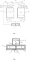
- FIG. 4 shows an air extracting cavity A and an air extracting cavity B, and accordingly, each of the foregoing components is denoted as a referential number composed of a component number and a corresponding letter.
- the air extracting channel on the air extracting cavity A is denoted as air extracting sub-channel 5A.
- FIG. 8 and FIG. 9 show a liquid cavity a and a liquid cavity b, and accordingly, each of the foregoing components is denoted as a referential number composed of a component number and a corresponding letter.
- the drainage channel provided in the liquid cavity a is denoted as drainage channel 6a.
- FIG. 2 is a schematic structural diagram of an air extractor according to the present invention.
- the device includes a liquid cavity 1, an air extracting cavity 2, blades 4, and a motor 3, where the liquid cavity contains liquid, the blades 4 are installed in the liquid cavity 1, and the motor 3 drives the blades 4 to rotate.
- the blades that are rotating drive the liquid in the liquid cavity to rotate.
- the liquid in the liquid cavity is in communication with the liquid in the air extracting cavity through a connection channel 7.
- a drainage channel 6 is further disposed on the liquid cavity, and the liquid cavity is in communication with an external environment through the drainage channel 6. In the liquid cavity 1, the position of the connection channel 7 is closer to the center of the rotating liquid than the position of the drainage channel 6.
- An air extracting channel 5 is disposed on the air extracting cavity 2, and the air extracting cavity is in communication with an object to be subjected to air extraction 8 (for example, an air tank, as shown in FIG. 3(a) ) through the air extracting channel 5. Air in the object to be subjected to air extraction is extracted and flows into the air extracting cavity 2 through the air extracting channel 5.
- the drainage channel 6 is disposed on the outermost side of the liquid cavity
- the connection channel 7 is disposed at the center of the liquid cavity.
- the positions of the drainage channel 6 and the connection channel 7 may also be set according to specific situations, provided that a communication position of the connection channel 7 and the liquid cavity is closer to the center of the rotating liquid than a communication position of the drainage channel 6 and the liquid cavity.
- the rotating liquid in the liquid cavity 1 generates a centrifugal inertia force. Since the density of the liquid is much higher than that of the air, the centrifugal inertia force of the rotating liquid is much greater than that of rotating air in FIG. 1 . Then, the pressure distribution with low central pressure and high peripheral pressure is formed in the liquid cavity.
- the liquid discharge channel 6 is in communication with the external environment, so that the pressure at the edge of the rotating liquid is equal to the pressure of the external environment.
- the position of the connection channel 7 is closer to the center of the rotating liquid than the position of the drainage channel 6, so that the pressure at the connection channel 7 is less than the pressure at the drainage channel 6 (equivalent to the pressure of the external environment).
- the pressure at the connection channel 7 is negative pressure.
- the liquid in the air extracting cavity 2 is extracted by the negative pressure through the connection channel 7, and is drained through the drainage channel 6.
- the liquid level in the air extracting cavity 2 decreases, so that the air pressure in the air extracting cavity decreases to form the negative pressure.
- the air in the object to be subjected to air extraction 8 is extracted by the negative pressure through the air extracting channel 5.
- FIG. 3 An example in which the object to be subjected to air extraction is an air tank is used for description.
- the air tank is in communication with the air extracting cavity 2 through the air extracting channel 5.
- the air extracting cavity is filled with liquid, and the liquid level 19 is located at the top of the air extracting cavity.
- the blades 4 start to rotate, forming a rotational liquid flow in the liquid cavity 1.
- Negative pressure (denoted as negative pressure A) is formed in the liquid cavity due to the centrifugal inertia force of the rotating liquid.
- the liquid in the air extracting cavity is extracted by the negative pressure A through the connection channel 7, so that the liquid level decreases, thereby forming negative pressure (negative pressure B) in the air extracting cavity.
- Air in the air tank is extracted by the negative pressure B of the air extracting cavity through the air extracting channel, so that the pressure in the air tank is reduced to form negative pressure (denoted as negative pressure C).
- negative pressure C negative pressure
- the negative pressure A is higher than the negative pressure B
- the negative pressure B is higher than the negative pressure C.
- the negative pressure A, negative pressure B, and negative pressure C will be balanced, that is, the negative pressure A is equal to the negative pressure B and the negative pressure C.
- the liquid level is kept stable at a height ( FIG. 3(b) ).
- a comparison between the air extractor of the present invention and the centrifugal evacuating pump as shown in FIG. 1 shows that the size and the rotational speed of blades of the two are the same. It is known that a centrifugal inertia force of a rotating fluid is proportional to the density of the fluid, so that the negative pressure formed by the centrifugal inertia force is also proportional to the density of the fluid. Obviously, final negative pressure formed by a centrifugal air extracting pump of FIG. 1 in an air tank may be much lower than that of the present invention.
- the rotating fluid in the centrifugal pump is air
- the rotating fluid of the present invention is the liquid with the density that is hundreds or even thousands of times that of the former (for example, the former is the air and the latter is water, and a density difference is 830 times).
- the centrifugal air extracting pump needs to reach the negative pressure of the present invention, the rotating speed of the blades thereof must be increased by about 30 times. Obviously, this is very difficult.
- the rotating speed of the motor is limited by electrical and mechanical properties of the motor (for example, a motor rotor coil, a rotating bearing, or rotating friction) and cannot be increased indefinitely.
- the present invention increases the negative pressure by using a high-density rotating fluid.
- the liquid is disposed in the air extracting cavity, and the liquid cavity must be in communication with the liquid in the air extracting cavity through the connection channel. This ensures that there is a rotational liquid flow in the liquid cavity during the extraction process. If the liquid is not disposed in the air extracting cavity, or the connection channel is in direct communication with the air in the air extracting cavity, the air may be extracted into the liquid cavity. Because the density of the air is less than that of the liquid, air may gather at the center of the rotational flow, forming a central air mass, and then squeeze out some or all of the liquid in the liquid cavity. With less rotary flowing of the liquid, the centrifugal inertia force becomes smaller, thereby weakening the negative pressure in the liquid cavity, and then weakening the negative pressure in the air extracting cavity.
- a piston-type air extracting pump in addition to the centrifugal air extracting pump, there may be a piston-type air extracting pump and a screw-type air extracting pump.
- the piston- type air extracting pump forms extremely high negative pressure through the reciprocating motion of a piston.
- the piston-type air extracting pump uses the motor and a crank slider mechanism, which is an asymmetric mechanical structure, to drive the reciprocating motion of the piston, the asymmetric mechanical structure has the disadvantage of extremely severe vibration, and the negative pressure may fluctuate due to the vibration.
- a screw-type air extracting pump extracts air and forms negative pressure through engagement of two screws. Screw engagement requires extremely high machining precision, which leads to high costs and heavy weight of the screw type air extracting pump.
- Blade motion of the present invention is axially symmetric and has no vibration problem, so the negative pressure is stable; and the blades driving the liquid to rotate do not require extremely high machining precision, so the costs of the centrifugal air extracting pump are extremely low.
- Embodiment 1 if the air is continuously extracted from the object to be subjected to air extraction 8, the liquid level 19 of the air extracting cavity 2 is decreased until there is no liquid in the air extracting cavity. If air extraction is further performed, the air enters the liquid cavity 1 and extrudes the liquid out of the liquid cavity. As a result, there is no rotary flowing of the liquid in the liquid cavity, so that the negative pressure is severely weakened.
- an air extracting cavity of the present invention may include two or more air extracting sub-cavities.
- a drainage channel includes two or more drainage sub-channels
- an air extracting channel includes two or more air extracting sub-channels
- a connection channel includes two or more connection sub-channels.
- the air extracting sub-cavity is in communication with the liquid cavity through the drainage sub-channel.
- the air extracting sub-cavity is further in communication with the liquid cavity through the connection sub-channel.
- the air extracting sub-cavity is in communication with an object to be subjected to air extraction through the air extracting sub-channel.
- an environment sub-channel is further disposed on the air extracting sub-cavity, and the air extracting sub-cavity is in communication with an external environment through the environment sub-channel.
- the air extractor further includes a switching mechanism for controlling opening and closing of the channel.
- air extracting cavities A and B are provided in this embodiment: an air extracting sub-cavity 2A and an air extracting sub-cavity 2B.
- the air extracting sub-cavity 2A corresponds to a connection sub-channel 7A, a drainage sub-channel 6A, an air extracting sub-channel 5A, and an environment sub-channel 9A; and the air extracting sub-cavity 2B corresponds to a connection sub-channel 7B, a drainage sub-channel 6B, an air extracting sub-channel 5B, and an environment sub-channel 9B.
- a switching mechanism is disposed on each of the drainage sub-channels, the air extracting sub-channels, the connection sub-channels, and the environment sub-channels.
- first switching mechanisms 10A and 10B are disposed on the connection sub-channels 7A and 7B respectively
- second switching mechanisms 11A and 11B are disposed on the drainage sub-channels 6A and 6B respectively
- third switching mechanisms 12A and 12B are disposed on the air extracting sub-channels 5A and 5B respectively
- fourth switching mechanisms 13A and 13B are disposed on the environment sub-channels 9A and 9B respectively.
- step (3) of Embodiment 2 when the third switching mechanism 12A is opened, and the third switching mechanism 12B is closed, the pressure in communication with the object to be subjected to air extraction 8 is suddenly changed from the negative pressure to the environment pressure.
- the sudden change in pressure is a sign of instability.
- this embodiment optimizes an action sequence of the switching mechanisms as follows:
- Embodiment 3 after the air extracting sub-channel 5A corresponding to the air extracting sub-cavity 2A is connected to the air extracting sub-cavity 5B corresponding to the air extracting sub-cavity 2B, the sub-channels are connected to the object to be subjected to air extraction through a main air extracting channel, and a main switching mechanism is disposed on the main air extracting channel.
- the main switching mechanism is first closed, and then the main switching mechanism is opened after the air extracting sub-cavities 2A and 2B communicate and the pressures of the two are balanced.
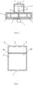
- an air bubble collection cavity 14 as shown in FIG. 5 is designed in this embodiment.
- the air bubble collection cavity 14 is disposed above the liquid cavity 1, and the air bubble collection cavity 14 is in communication with the liquid cavity 1 through an air bubble channel 15.
- the air bubble channel 15 is disposed at a rotary flowing center in the liquid cavity 1.
- the buoyancy of the air bubbles is utilized to separate the separated air from rotary liquid flowing, avoiding gathering of the air mass in the rotary flowing center of the liquid.
- a communication position of a connection channel 7 and the liquid cavity 1 is disposed at the lower part of the liquid cavity 1, as shown in FIG. 5 .
- the liquid extracted from the air extracting cavity 2 has an upward flow rate as when flowing into the liquid cavity, which also helps convey the air bubbles to the air bubble collection cavity.
- An air release channel 21 and an air release mechanism 22 are also disposed on the air bubble collection cavity 14 in FIG. 6 .
- the air bubble collection cavity 14 is in communication with the air release mechanism 22 through the air release channel 21.
- the air release mechanism 22 can discharge the air in the air bubble collection cavity.
- the air release mechanism 22 may be a switching mechanism. After each use of the air extractor, the switching mechanism of the air release mechanism 22 is opened, so that the air bubble collection cavity 14 is in communication with an external environment. Once the liquid level in the air bubble collection cavity 14 is lower than the liquid level in the air extracting cavity 2, the liquid flows from the air extracting cavity 2 into the air bubble collection cavity 14 under the action of gravity, and extrudes the air in the air bubble collection cavity out, so that the air bubble collection cavity is filled with the liquid once again.
- the air release mechanism 22 may also be a small vacuum pump. When the air extractor is operating, the vacuum pump is turned on to extract the air out of the air bubble collection cavity.
- the liquid in the air extracting cavity 2 is always in contact with the air, so that the air is continuously dissolved into the liquid, the newly dissolved air may be continuously separated out under the condition of a negative pressure of the liquid cavity 1. This may lead to a continuous increase of the air in the liquid cavity 1.
- the air mass gathering at the center of the liquid cavity 1 becomes larger and larger.
- the volume of the air in the air bubble collection cavity 14 is continuously increased, and finally the air fills the air bubble collection cavity 14 and then overflows into the liquid cavity 1, which is not beneficial to further increase of the negative pressure. Therefore, the present invention further needs to resolve the problem of continuous air separation.
- the solution of the present invention is to reduce contact between the liquid and the air, thereby reducing the amount of air dissolved into the liquid.
- a specific method is shown in FIG. 7 .
- An air-liquid blocker 16 is disposed on the liquid level of the air extracting cavity.
- the air-liquid blocker 16 is configured to block the contact between the liquid and the air in the air extracting cavity 2, thereby achieving the purpose of reducing or preventing the air from being dissolved into the liquid.
- the air-liquid blocker 16 may be another liquid that is less dense than the liquid in air extracting cavity 2 and is difficult to dissolve air.
- the liquid in the air extracting cavity 2 is water
- the air-liquid blocker 16 is oil.
- the oil floats above the water, blocking the contact between the air and the water and also preventing the air from being dissolved into the water.
- the air-liquid blocker 16 may also be a solid plate floating on the liquid, or a ball floating on the liquid (as shown in FIG. 8 ) and capable of moving up and down with the liquid level.
- two liquid cavities are connected in series to enhance the negative pressure for air extraction.
- a liquid cavity a and a liquid cavity b are used.
- the liquid cavity a is in communication with an air extracting cavity 2 through a connection channel 7a.
- a drainage channel 6a of the liquid cavity a is in communication with a connection channel 7b of the liquid cavity b.
- a drainage channel 6b of the liquid cavity b drains liquid outward. If the pressure of the drainage channel 6b is an environmental pressure, the pressure of the connection channel 7a is the sum of negative pressure generated by the two liquid cavities.
- the negative pressure for air extraction may be further increased by increasing the number of liquid cavities connected in series in other embodiments of the present invention.
- two liquid cavities are connected in parallel to enhance an air extraction amount.
- a liquid cavity a and a liquid cavity b are used.
- a drainage channel 7a of the liquid cavity a is in communication with a connection channel 7b of the liquid cavity b, and is in communication with an air extracting cavity 2.
- a drainage channel 6a of the liquid cavity a is in communication with a drainage channel 6b of the liquid cavity b, to drain liquid outward.
- the flow of liquid from the air extracting cavity 2 is the sum of the flows of the two liquid cavities, which increases the amount of liquid inflow and also increases the air extraction amount of the air extracting cavity.
- the negative pressure for air extraction may be further increased by increasing the number of liquid cavities connected in parallel in other embodiments of the present invention.
Landscapes
- Engineering & Computer Science (AREA)
- Mechanical Engineering (AREA)
- General Engineering & Computer Science (AREA)
- Physics & Mathematics (AREA)
- Fluid Mechanics (AREA)
- Extraction Or Liquid Replacement (AREA)
- Structures Of Non-Positive Displacement Pumps (AREA)
- Jet Pumps And Other Pumps (AREA)
Applications Claiming Priority (1)
| Application Number | Priority Date | Filing Date | Title |
|---|---|---|---|
| CN202210553496.XA CN115263755A (zh) | 2022-05-20 | 2022-05-20 | 一种抽气装置 |
Publications (3)
| Publication Number | Publication Date |
|---|---|
| EP4279737A1 true EP4279737A1 (fr) | 2023-11-22 |
| EP4279737B1 EP4279737B1 (fr) | 2025-07-09 |
| EP4279737C0 EP4279737C0 (fr) | 2025-07-09 |
Family
ID=83760152
Family Applications (1)
| Application Number | Title | Priority Date | Filing Date |
|---|---|---|---|
| EP23174199.2A Active EP4279737B1 (fr) | 2022-05-20 | 2023-05-19 | Extracteur d'air doté d'une pompe à liquide |
Country Status (4)
| Country | Link |
|---|---|
| US (1) | US20230375007A1 (fr) |
| EP (1) | EP4279737B1 (fr) |
| JP (1) | JP7506938B2 (fr) |
| CN (1) | CN115263755A (fr) |
Cited By (3)
| Publication number | Priority date | Publication date | Assignee | Title |
|---|---|---|---|---|
| US20220204194A1 (en) * | 2020-08-20 | 2022-06-30 | Shenzhenshi Yuzhan Precision Technology Co., Ltd. | Liquid loading device and liquid loading method |
| CN119353228A (zh) * | 2024-12-25 | 2025-01-24 | 烟台恒邦泵业有限公司 | 一种双吸离心泵 |
| CN120532512A (zh) * | 2025-07-29 | 2025-08-26 | 安徽建筑大学 | 一种蜂窝球状锰铜双金属氧化物脱硝催化剂及其制备方法和设备 |
Citations (5)
| Publication number | Priority date | Publication date | Assignee | Title |
|---|---|---|---|---|
| FR1215191A (fr) * | 1958-11-10 | 1960-04-15 | Procédé de production de gaz comprimé par piston liquide et par pompe centrifuge ou conduite forcée | |
| EP1510698A2 (fr) * | 2003-08-26 | 2005-03-02 | Herborner Pumpenfabrik J.H.Hoffmann GmbH & Co. | Dispositif pour la protection d'une pompe dans l'absence d'eau |
| WO2011110053A1 (fr) * | 2010-03-09 | 2011-09-15 | 北京瞬节科技有限公司 | Dispositif et procédé de dégazage centrifuge sous vide |
| US20190032851A1 (en) * | 2016-01-18 | 2019-01-31 | Cryostar Sas | Apparatus and method for compressing evaporated gas |
| JP2021161887A (ja) * | 2020-03-31 | 2021-10-11 | 和幸 前田 | 気体の吸引・圧送装置及び気体の吸引・圧送方法 |
Family Cites Families (11)
| Publication number | Priority date | Publication date | Assignee | Title |
|---|---|---|---|---|
| GB221575A (en) * | 1923-06-15 | 1924-09-15 | John Wilkinson Greig | Improved vacuum producing apparatus |
| BE683692A (fr) * | 1965-07-09 | 1967-01-06 | ||
| FI45411C (fi) * | 1967-03-30 | 1972-06-12 | Gelleco Ab | Laite kaasun imemiseksi pyörre-erottimesta |
| JPH01143607A (ja) * | 1987-11-30 | 1989-06-06 | Mitsubishi Oil Co Ltd | 気泡を分離拝出するポンプ |
| JP2567668B2 (ja) * | 1988-06-16 | 1996-12-25 | 三洋電機株式会社 | 電気掃除機 |
| JPH0617784A (ja) * | 1991-10-03 | 1994-01-25 | Ouken Seiko Kk | 遠心ポンプ |
| JPH08171000A (ja) * | 1994-12-19 | 1996-07-02 | Toshiba Corp | 沸騰水型原子力発電プラント |
| JP3397154B2 (ja) * | 1997-12-30 | 2003-04-14 | 博文 大成 | 旋回式微細気泡発生装置 |
| CN2714857Y (zh) * | 2004-07-23 | 2005-08-03 | 唐兴民 | 自吸排气式磁力泵 |
| CN213574644U (zh) | 2020-08-31 | 2021-06-29 | 广州兴森快捷电路科技有限公司 | 防空吸缓冲装置及泵吸装置 |
| CN214884053U (zh) | 2021-01-05 | 2021-11-26 | 中电建路桥集团有限公司 | 负压取水装置 |
-
2022
- 2022-05-20 CN CN202210553496.XA patent/CN115263755A/zh active Pending
-
2023
- 2023-03-17 JP JP2023043130A patent/JP7506938B2/ja active Active
- 2023-05-19 US US18/320,657 patent/US20230375007A1/en active Pending
- 2023-05-19 EP EP23174199.2A patent/EP4279737B1/fr active Active
Patent Citations (5)
| Publication number | Priority date | Publication date | Assignee | Title |
|---|---|---|---|---|
| FR1215191A (fr) * | 1958-11-10 | 1960-04-15 | Procédé de production de gaz comprimé par piston liquide et par pompe centrifuge ou conduite forcée | |
| EP1510698A2 (fr) * | 2003-08-26 | 2005-03-02 | Herborner Pumpenfabrik J.H.Hoffmann GmbH & Co. | Dispositif pour la protection d'une pompe dans l'absence d'eau |
| WO2011110053A1 (fr) * | 2010-03-09 | 2011-09-15 | 北京瞬节科技有限公司 | Dispositif et procédé de dégazage centrifuge sous vide |
| US20190032851A1 (en) * | 2016-01-18 | 2019-01-31 | Cryostar Sas | Apparatus and method for compressing evaporated gas |
| JP2021161887A (ja) * | 2020-03-31 | 2021-10-11 | 和幸 前田 | 気体の吸引・圧送装置及び気体の吸引・圧送方法 |
Cited By (4)
| Publication number | Priority date | Publication date | Assignee | Title |
|---|---|---|---|---|
| US20220204194A1 (en) * | 2020-08-20 | 2022-06-30 | Shenzhenshi Yuzhan Precision Technology Co., Ltd. | Liquid loading device and liquid loading method |
| US12168536B2 (en) * | 2020-08-20 | 2024-12-17 | Fulian Yuzhan Precision Technology Co., Ltd | Liquid loading device and liquid loading method |
| CN119353228A (zh) * | 2024-12-25 | 2025-01-24 | 烟台恒邦泵业有限公司 | 一种双吸离心泵 |
| CN120532512A (zh) * | 2025-07-29 | 2025-08-26 | 安徽建筑大学 | 一种蜂窝球状锰铜双金属氧化物脱硝催化剂及其制备方法和设备 |
Also Published As
| Publication number | Publication date |
|---|---|
| EP4279737B1 (fr) | 2025-07-09 |
| EP4279737C0 (fr) | 2025-07-09 |
| CN115263755A (zh) | 2022-11-01 |
| US20230375007A1 (en) | 2023-11-23 |
| JP2023171247A (ja) | 2023-12-01 |
| JP7506938B2 (ja) | 2024-06-27 |
Similar Documents
| Publication | Publication Date | Title |
|---|---|---|
| EP4279737B1 (fr) | Extracteur d'air doté d'une pompe à liquide | |
| CN103244438B (zh) | 牵引级复合分子泵 | |
| CN117967582A (zh) | 一种泵站启动用真空稳压补水装置 | |
| KR20200043423A (ko) | 유체를 펌핑하기 위한 펌프 및 방법 | |
| CN107366618A (zh) | 一种可提高低转速下泵送效率的叶片泵 | |
| EP4196684A1 (fr) | Pompe à palette hydraulique | |
| US3395854A (en) | Compressor | |
| CN112474081A (zh) | 一种在对生物细胞进行离心提取物质稳定离心速度装置 | |
| US12398725B2 (en) | Multi-phase rotor, system and method for maintaining a stable vapour cavity | |
| Qin et al. | Differential evolutionary modeling and starting-up cavitation characteristics analysis for multistage centrifugal pump | |
| CN206626150U (zh) | 一种可靠性防水防尘耦合器壳体 | |
| CN209621607U (zh) | 一种压缩机及其机芯 | |
| CN111963450B (zh) | 一种智能化自动降温潜水泵 | |
| CN108730233B (zh) | 一种提高侧流道泵效率的方法 | |
| CN218416109U (zh) | 油冷驱动系统及回油结构 | |
| CN211288252U (zh) | 一种新型节能的微型循环冷却泵 | |
| CN108386388B (zh) | 一种相同流量扬程可选的超低比转速泵及设计方法 | |
| JP2005214192A (ja) | ガス摩擦ポンプ | |
| RU2520797C2 (ru) | Погружной многоступенчатый модульный насос и ступень насоса | |
| CN221879716U (zh) | 一种船用磁力多级离心泵的自动排气装置 | |
| RU205750U1 (ru) | Рабочее колесо погружного многоступенчатого лопастного насоса | |
| CN118148932B (zh) | 一种便于气液分离的磁悬浮自吸泵 | |
| US12038012B2 (en) | Centrifugal pump | |
| CN218981934U (zh) | 一种冬青油生产用油状物离心分离装置 | |
| CN213494331U (zh) | 一种高效离心式分离器 |
Legal Events
| Date | Code | Title | Description |
|---|---|---|---|
| PUAI | Public reference made under article 153(3) epc to a published international application that has entered the european phase |
Free format text: ORIGINAL CODE: 0009012 |
|
| STAA | Information on the status of an ep patent application or granted ep patent |
Free format text: STATUS: THE APPLICATION HAS BEEN PUBLISHED |
|
| AK | Designated contracting states |
Kind code of ref document: A1 Designated state(s): AL AT BE BG CH CY CZ DE DK EE ES FI FR GB GR HR HU IE IS IT LI LT LU LV MC ME MK MT NL NO PL PT RO RS SE SI SK SM TR |
|
| STAA | Information on the status of an ep patent application or granted ep patent |
Free format text: STATUS: REQUEST FOR EXAMINATION WAS MADE |
|
| 17P | Request for examination filed |
Effective date: 20240322 |
|
| RBV | Designated contracting states (corrected) |
Designated state(s): AL AT BE BG CH CY CZ DE DK EE ES FI FR GB GR HR HU IE IS IT LI LT LU LV MC ME MK MT NL NO PL PT RO RS SE SI SK SM TR |
|
| STAA | Information on the status of an ep patent application or granted ep patent |
Free format text: STATUS: EXAMINATION IS IN PROGRESS |
|
| 17Q | First examination report despatched |
Effective date: 20240701 |
|
| REG | Reference to a national code |
Ref country code: DE Ref legal event code: R079 Free format text: PREVIOUS MAIN CLASS: F04B0035000000 Ipc: F04D0017180000 Ref country code: DE Ref legal event code: R079 Ref document number: 602023004640 Country of ref document: DE Free format text: PREVIOUS MAIN CLASS: F04B0035000000 Ipc: F04D0017180000 |
|
| GRAP | Despatch of communication of intention to grant a patent |
Free format text: ORIGINAL CODE: EPIDOSNIGR1 |
|
| STAA | Information on the status of an ep patent application or granted ep patent |
Free format text: STATUS: GRANT OF PATENT IS INTENDED |
|
| RIC1 | Information provided on ipc code assigned before grant |
Ipc: F04F 5/08 20060101ALI20241202BHEP Ipc: F04F 5/06 20060101ALI20241202BHEP Ipc: F04B 53/14 20060101ALI20241202BHEP Ipc: F04B 41/02 20060101ALI20241202BHEP Ipc: F04B 39/00 20060101ALI20241202BHEP Ipc: F04B 37/14 20060101ALI20241202BHEP Ipc: F04B 35/00 20060101ALI20241202BHEP Ipc: F04D 17/18 20060101AFI20241202BHEP |
|
| INTG | Intention to grant announced |
Effective date: 20250103 |
|
| GRAS | Grant fee paid |
Free format text: ORIGINAL CODE: EPIDOSNIGR3 |
|
| GRAA | (expected) grant |
Free format text: ORIGINAL CODE: 0009210 |
|
| STAA | Information on the status of an ep patent application or granted ep patent |
Free format text: STATUS: THE PATENT HAS BEEN GRANTED |
|
| AK | Designated contracting states |
Kind code of ref document: B1 Designated state(s): AL AT BE BG CH CY CZ DE DK EE ES FI FR GB GR HR HU IE IS IT LI LT LU LV MC ME MK MT NL NO PL PT RO RS SE SI SK SM TR |
|
| REG | Reference to a national code |
Ref country code: GB Ref legal event code: FG4D |
|
| REG | Reference to a national code |
Ref country code: CH Ref legal event code: EP |
|
| REG | Reference to a national code |
Ref country code: IE Ref legal event code: FG4D |
|
| REG | Reference to a national code |
Ref country code: DE Ref legal event code: R096 Ref document number: 602023004640 Country of ref document: DE |
|
| U01 | Request for unitary effect filed |
Effective date: 20250801 |
|
| U07 | Unitary effect registered |
Designated state(s): AT BE BG DE DK EE FI FR IT LT LU LV MT NL PT RO SE SI Effective date: 20250812 |
|
| PG25 | Lapsed in a contracting state [announced via postgrant information from national office to epo] |
Ref country code: IS Free format text: LAPSE BECAUSE OF FAILURE TO SUBMIT A TRANSLATION OF THE DESCRIPTION OR TO PAY THE FEE WITHIN THE PRESCRIBED TIME-LIMIT Effective date: 20251109 |
|
| PG25 | Lapsed in a contracting state [announced via postgrant information from national office to epo] |
Ref country code: NO Free format text: LAPSE BECAUSE OF FAILURE TO SUBMIT A TRANSLATION OF THE DESCRIPTION OR TO PAY THE FEE WITHIN THE PRESCRIBED TIME-LIMIT Effective date: 20251009 |
|
| PG25 | Lapsed in a contracting state [announced via postgrant information from national office to epo] |
Ref country code: HR Free format text: LAPSE BECAUSE OF FAILURE TO SUBMIT A TRANSLATION OF THE DESCRIPTION OR TO PAY THE FEE WITHIN THE PRESCRIBED TIME-LIMIT Effective date: 20250709 |
|
| PG25 | Lapsed in a contracting state [announced via postgrant information from national office to epo] |
Ref country code: GR Free format text: LAPSE BECAUSE OF FAILURE TO SUBMIT A TRANSLATION OF THE DESCRIPTION OR TO PAY THE FEE WITHIN THE PRESCRIBED TIME-LIMIT Effective date: 20251010 |
|
| PG25 | Lapsed in a contracting state [announced via postgrant information from national office to epo] |
Ref country code: PL Free format text: LAPSE BECAUSE OF FAILURE TO SUBMIT A TRANSLATION OF THE DESCRIPTION OR TO PAY THE FEE WITHIN THE PRESCRIBED TIME-LIMIT Effective date: 20250709 |
|
| PG25 | Lapsed in a contracting state [announced via postgrant information from national office to epo] |
Ref country code: RS Free format text: LAPSE BECAUSE OF FAILURE TO SUBMIT A TRANSLATION OF THE DESCRIPTION OR TO PAY THE FEE WITHIN THE PRESCRIBED TIME-LIMIT Effective date: 20251009 |
|
| PG25 | Lapsed in a contracting state [announced via postgrant information from national office to epo] |
Ref country code: ES Free format text: LAPSE BECAUSE OF FAILURE TO SUBMIT A TRANSLATION OF THE DESCRIPTION OR TO PAY THE FEE WITHIN THE PRESCRIBED TIME-LIMIT Effective date: 20250709 |
|
| PG25 | Lapsed in a contracting state [announced via postgrant information from national office to epo] |
Ref country code: SM Free format text: LAPSE BECAUSE OF FAILURE TO SUBMIT A TRANSLATION OF THE DESCRIPTION OR TO PAY THE FEE WITHIN THE PRESCRIBED TIME-LIMIT Effective date: 20250709 |
|
| PG25 | Lapsed in a contracting state [announced via postgrant information from national office to epo] |
Ref country code: CZ Free format text: LAPSE BECAUSE OF FAILURE TO SUBMIT A TRANSLATION OF THE DESCRIPTION OR TO PAY THE FEE WITHIN THE PRESCRIBED TIME-LIMIT Effective date: 20250709 |
|
| PG25 | Lapsed in a contracting state [announced via postgrant information from national office to epo] |
Ref country code: SK Free format text: LAPSE BECAUSE OF FAILURE TO SUBMIT A TRANSLATION OF THE DESCRIPTION OR TO PAY THE FEE WITHIN THE PRESCRIBED TIME-LIMIT Effective date: 20250709 |
|
| PLBE | No opposition filed within time limit |
Free format text: ORIGINAL CODE: 0009261 |
|
| STAA | Information on the status of an ep patent application or granted ep patent |
Free format text: STATUS: NO OPPOSITION FILED WITHIN TIME LIMIT |