EP4279774A1 - Vanne de commande - Google Patents
Vanne de commande Download PDFInfo
- Publication number
- EP4279774A1 EP4279774A1 EP21918949.5A EP21918949A EP4279774A1 EP 4279774 A1 EP4279774 A1 EP 4279774A1 EP 21918949 A EP21918949 A EP 21918949A EP 4279774 A1 EP4279774 A1 EP 4279774A1
- Authority
- EP
- European Patent Office
- Prior art keywords
- sealing member
- side wall
- limiting rib
- limiting
- arc length
- Prior art date
- Legal status (The legal status is an assumption and is not a legal conclusion. Google has not performed a legal analysis and makes no representation as to the accuracy of the status listed.)
- Pending
Links
Images


Classifications
-
- F—MECHANICAL ENGINEERING; LIGHTING; HEATING; WEAPONS; BLASTING
- F16—ENGINEERING ELEMENTS AND UNITS; GENERAL MEASURES FOR PRODUCING AND MAINTAINING EFFECTIVE FUNCTIONING OF MACHINES OR INSTALLATIONS; THERMAL INSULATION IN GENERAL
- F16K—VALVES; TAPS; COCKS; ACTUATING-FLOATS; DEVICES FOR VENTING OR AERATING
- F16K11/00—Multiple-way valves, e.g. mixing valves; Pipe fittings incorporating such valves
- F16K11/02—Multiple-way valves, e.g. mixing valves; Pipe fittings incorporating such valves with all movable sealing faces moving as one unit
- F16K11/08—Multiple-way valves, e.g. mixing valves; Pipe fittings incorporating such valves with all movable sealing faces moving as one unit comprising only taps or cocks
- F16K11/085—Multiple-way valves, e.g. mixing valves; Pipe fittings incorporating such valves with all movable sealing faces moving as one unit comprising only taps or cocks with cylindrical plug
- F16K11/0856—Multiple-way valves, e.g. mixing valves; Pipe fittings incorporating such valves with all movable sealing faces moving as one unit comprising only taps or cocks with cylindrical plug having all the connecting conduits situated in more than one plane perpendicular to the axis of the plug
-
- F—MECHANICAL ENGINEERING; LIGHTING; HEATING; WEAPONS; BLASTING
- F16—ENGINEERING ELEMENTS AND UNITS; GENERAL MEASURES FOR PRODUCING AND MAINTAINING EFFECTIVE FUNCTIONING OF MACHINES OR INSTALLATIONS; THERMAL INSULATION IN GENERAL
- F16K—VALVES; TAPS; COCKS; ACTUATING-FLOATS; DEVICES FOR VENTING OR AERATING
- F16K5/00—Plug valves; Taps or cocks comprising only cut-off apparatus having at least one of the sealing faces shaped as a more or less complete surface of a solid of revolution, the opening and closing movement being predominantly rotary
- F16K5/04—Plug valves; Taps or cocks comprising only cut-off apparatus having at least one of the sealing faces shaped as a more or less complete surface of a solid of revolution, the opening and closing movement being predominantly rotary with plugs having cylindrical surfaces; Packings therefor
- F16K5/0457—Packings
- F16K5/0471—Packings between housing and plug
-
- F—MECHANICAL ENGINEERING; LIGHTING; HEATING; WEAPONS; BLASTING
- F16—ENGINEERING ELEMENTS AND UNITS; GENERAL MEASURES FOR PRODUCING AND MAINTAINING EFFECTIVE FUNCTIONING OF MACHINES OR INSTALLATIONS; THERMAL INSULATION IN GENERAL
- F16K—VALVES; TAPS; COCKS; ACTUATING-FLOATS; DEVICES FOR VENTING OR AERATING
- F16K11/00—Multiple-way valves, e.g. mixing valves; Pipe fittings incorporating such valves
- F16K11/02—Multiple-way valves, e.g. mixing valves; Pipe fittings incorporating such valves with all movable sealing faces moving as one unit
- F16K11/06—Multiple-way valves, e.g. mixing valves; Pipe fittings incorporating such valves with all movable sealing faces moving as one unit comprising only sliding valves, i.e. sliding closure elements
- F16K11/072—Multiple-way valves, e.g. mixing valves; Pipe fittings incorporating such valves with all movable sealing faces moving as one unit comprising only sliding valves, i.e. sliding closure elements with pivoted closure members
- F16K11/076—Multiple-way valves, e.g. mixing valves; Pipe fittings incorporating such valves with all movable sealing faces moving as one unit comprising only sliding valves, i.e. sliding closure elements with pivoted closure members with sealing faces shaped as surfaces of solids of revolution
-
- F—MECHANICAL ENGINEERING; LIGHTING; HEATING; WEAPONS; BLASTING
- F16—ENGINEERING ELEMENTS AND UNITS; GENERAL MEASURES FOR PRODUCING AND MAINTAINING EFFECTIVE FUNCTIONING OF MACHINES OR INSTALLATIONS; THERMAL INSULATION IN GENERAL
- F16K—VALVES; TAPS; COCKS; ACTUATING-FLOATS; DEVICES FOR VENTING OR AERATING
- F16K11/00—Multiple-way valves, e.g. mixing valves; Pipe fittings incorporating such valves
- F16K11/02—Multiple-way valves, e.g. mixing valves; Pipe fittings incorporating such valves with all movable sealing faces moving as one unit
- F16K11/08—Multiple-way valves, e.g. mixing valves; Pipe fittings incorporating such valves with all movable sealing faces moving as one unit comprising only taps or cocks
- F16K11/085—Multiple-way valves, e.g. mixing valves; Pipe fittings incorporating such valves with all movable sealing faces moving as one unit comprising only taps or cocks with cylindrical plug
-
- F—MECHANICAL ENGINEERING; LIGHTING; HEATING; WEAPONS; BLASTING
- F16—ENGINEERING ELEMENTS AND UNITS; GENERAL MEASURES FOR PRODUCING AND MAINTAINING EFFECTIVE FUNCTIONING OF MACHINES OR INSTALLATIONS; THERMAL INSULATION IN GENERAL
- F16K—VALVES; TAPS; COCKS; ACTUATING-FLOATS; DEVICES FOR VENTING OR AERATING
- F16K11/00—Multiple-way valves, e.g. mixing valves; Pipe fittings incorporating such valves
- F16K11/02—Multiple-way valves, e.g. mixing valves; Pipe fittings incorporating such valves with all movable sealing faces moving as one unit
- F16K11/08—Multiple-way valves, e.g. mixing valves; Pipe fittings incorporating such valves with all movable sealing faces moving as one unit comprising only taps or cocks
- F16K11/085—Multiple-way valves, e.g. mixing valves; Pipe fittings incorporating such valves with all movable sealing faces moving as one unit comprising only taps or cocks with cylindrical plug
- F16K11/0853—Multiple-way valves, e.g. mixing valves; Pipe fittings incorporating such valves with all movable sealing faces moving as one unit comprising only taps or cocks with cylindrical plug having all the connecting conduits situated in a single plane perpendicular to the axis of the plug
-
- F—MECHANICAL ENGINEERING; LIGHTING; HEATING; WEAPONS; BLASTING
- F16—ENGINEERING ELEMENTS AND UNITS; GENERAL MEASURES FOR PRODUCING AND MAINTAINING EFFECTIVE FUNCTIONING OF MACHINES OR INSTALLATIONS; THERMAL INSULATION IN GENERAL
- F16K—VALVES; TAPS; COCKS; ACTUATING-FLOATS; DEVICES FOR VENTING OR AERATING
- F16K27/00—Construction of housing; Use of materials therefor
- F16K27/04—Construction of housing; Use of materials therefor of sliding valves
- F16K27/041—Construction of housing; Use of materials therefor of sliding valves cylindrical slide valves
-
- F—MECHANICAL ENGINEERING; LIGHTING; HEATING; WEAPONS; BLASTING
- F16—ENGINEERING ELEMENTS AND UNITS; GENERAL MEASURES FOR PRODUCING AND MAINTAINING EFFECTIVE FUNCTIONING OF MACHINES OR INSTALLATIONS; THERMAL INSULATION IN GENERAL
- F16K—VALVES; TAPS; COCKS; ACTUATING-FLOATS; DEVICES FOR VENTING OR AERATING
- F16K27/00—Construction of housing; Use of materials therefor
- F16K27/06—Construction of housing; Use of materials therefor of taps or cocks
-
- F—MECHANICAL ENGINEERING; LIGHTING; HEATING; WEAPONS; BLASTING
- F16—ENGINEERING ELEMENTS AND UNITS; GENERAL MEASURES FOR PRODUCING AND MAINTAINING EFFECTIVE FUNCTIONING OF MACHINES OR INSTALLATIONS; THERMAL INSULATION IN GENERAL
- F16K—VALVES; TAPS; COCKS; ACTUATING-FLOATS; DEVICES FOR VENTING OR AERATING
- F16K27/00—Construction of housing; Use of materials therefor
- F16K27/06—Construction of housing; Use of materials therefor of taps or cocks
- F16K27/065—Construction of housing; Use of materials therefor of taps or cocks with cylindrical plugs
-
- F—MECHANICAL ENGINEERING; LIGHTING; HEATING; WEAPONS; BLASTING
- F16—ENGINEERING ELEMENTS AND UNITS; GENERAL MEASURES FOR PRODUCING AND MAINTAINING EFFECTIVE FUNCTIONING OF MACHINES OR INSTALLATIONS; THERMAL INSULATION IN GENERAL
- F16K—VALVES; TAPS; COCKS; ACTUATING-FLOATS; DEVICES FOR VENTING OR AERATING
- F16K3/00—Gate valves or sliding valves, i.e. cut-off apparatus with closing members having a sliding movement along the seat for opening and closing
- F16K3/22—Gate valves or sliding valves, i.e. cut-off apparatus with closing members having a sliding movement along the seat for opening and closing with sealing faces shaped as surfaces of solids of revolution
- F16K3/24—Gate valves or sliding valves, i.e. cut-off apparatus with closing members having a sliding movement along the seat for opening and closing with sealing faces shaped as surfaces of solids of revolution with cylindrical valve members
- F16K3/243—Packings
-
- F—MECHANICAL ENGINEERING; LIGHTING; HEATING; WEAPONS; BLASTING
- F16—ENGINEERING ELEMENTS AND UNITS; GENERAL MEASURES FOR PRODUCING AND MAINTAINING EFFECTIVE FUNCTIONING OF MACHINES OR INSTALLATIONS; THERMAL INSULATION IN GENERAL
- F16K—VALVES; TAPS; COCKS; ACTUATING-FLOATS; DEVICES FOR VENTING OR AERATING
- F16K5/00—Plug valves; Taps or cocks comprising only cut-off apparatus having at least one of the sealing faces shaped as a more or less complete surface of a solid of revolution, the opening and closing movement being predominantly rotary
- F16K5/04—Plug valves; Taps or cocks comprising only cut-off apparatus having at least one of the sealing faces shaped as a more or less complete surface of a solid of revolution, the opening and closing movement being predominantly rotary with plugs having cylindrical surfaces; Packings therefor
- F16K5/0407—Plug valves; Taps or cocks comprising only cut-off apparatus having at least one of the sealing faces shaped as a more or less complete surface of a solid of revolution, the opening and closing movement being predominantly rotary with plugs having cylindrical surfaces; Packings therefor with particular plug arrangements, e.g. particular shape or built-in means
Definitions
- the present application relates to the technical field of fluid control, and in particular to a control valve.
- a motor vehicle may generally have multiple control valves in order to conduct controlling at present.
- a sealing member is generally provided between a valve body and a valve core assembly for sealing. During the assembly of the sealing member and valve body, it may cause local deformation of the sealing member during the assembly, thus affecting the sealing effect.
- An object according to the present application is to provide a control valve that can limit a position of a sealing member, prevent the sealing member from generating local deformation during assembly, and improve the sealing effect of the sealing member.
- a control valve is provided according to an embodiment of the present application, which includes a valve body, a valve core assembly and a sealing member, the valve body has a mounting cavity, at least part of the valve core assembly is located in the mounting cavity, where the valve body includes a bottom wall, a side wall and a position-limiting rib, the side wall protrudes from the bottom wall, the position-limiting rib includes an arc section, the position-limiting rib is located in a space defined by the side wall and the bottom wall and protrudes from the bottom wall, a gap is formed between the side wall and the position-limiting rib, the sealing member includes a first portion and a second portion, the first portion is close to an axial end of the sealing member, the second portion is located between the valve core assembly and the side wall, the first portion is fixedly connected to the second portion, and the first portion is located in the gap.
- the control valve includes the valve body, the valve core assembly and the sealing member, and the sealing member is located between the valve core assembly and the side wall of the valve body, which can realize the sealing performance of the sealing member.
- the sealing member and the valve body are two separate members, in order to limit an assembly position of the sealing member on the valve body during mounting the sealing member on the valve body, the position-limiting rib is provided in the valve body, the gap is formed between the side wall and the position-limiting rib, and the first portion of the sealing member is arranged in the gap between the side wall and the position-limiting rib during the assembly of the sealing member and the valve body, so that the position-limiting rib can limit the assembly position of the sealing member on the valve body.
- the arc length of the sealing member can be limited by the position-limiting rib, which can reduce the local deformation of the sealing member during assembly, thereby improving the sealing performance of the control valve and improving the stability and quality of the control valve.
- a control valve in the field of control valves for fluid control, includes a valve body, a valve core assembly and a sealing member located between the valve body and the valve core assembly, the valve body has a mounting cavity, at least part of the valve core assembly is located in the mounting cavity, the valve core assembly is driven to rotate by a driving device, and the sealing member is configured to seal a gap between the valve core assembly and the valve body, so as to prevent the valve core assembly from leaking during operation.
- valve body and the sealing member are arranged separately, that is, the sealing member and the valve body are two separate members, then the separate sealing member and the separate valve body are manually assembled together, and then the sealing member is extruded after the valve core assembly 300 is assembled into a mounting space formed by the sealing member, so that a sealing condition among the valve body, the sealing member and the valve core assembly is formed.
- a position-limiting member may be provided in the valve body, so as to mount the sealing member between the position-limiting member and the side wall of the valve body.
- a structure of the position-limiting member is an important factor, which may cause a part of the sealing member not to be limited by the position-limiting member, and may easily cause the deformation of the sealing member, such as the curling of the sealing member, during the assembly of the sealing member and the valve body or during the assembly of the valve core assembly and the sealing member, thereby effecting the sealing performance of the control valve.
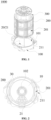
- a control valve 1000 is provided according to an embodiment of the present application.
- the control valve 1000 according to the embodiment of the present application is described below with reference to the accompanying drawings.
- the control valve 1000 includes a valve body 100, a valve core assembly 300 and a sealing member 200.
- the valve body 100 has a mounting cavity 101, at least part of the valve core assembly 300 is located in the mounting cavity 101, the valve core assembly 300 is rotatable, for example, the valve core assembly is driven to be rotatable by an external driving member, so as to control the fluid.
- the valve body 100 includes a side wall 20, the sealing member 200 is located in the mounting cavity 101 and is arranged between the side wall 20 of the valve body 100 and the valve core assembly 300, so as to seal a gap between the side wall 20 of the valve body 100 and the valve core assembly 300, thereby improving the quality and stability of the control valve 1000.
- the side wall 20 is a side wall which defines the mounting cavity 101, and the side wall 20 includes an inner contour and an outer contour, and shapes of the inner contour and the outer contour may be the same or different.
- the inner contour of the side wall 20 is in a cylindrical surface, and the outer contour of the side wall includes a mounting flat surface, so as to facilitate of fitting the control valve 1000.
- the valve body 100 includes a bottom wall 10, a side wall 20 and a position-limiting rib 30, and the side wall 20 protrudes from the bottom wall 10.
- the position-limiting rib 30 includes an arc section, the position-limiting rib 30 is located in a space defined by the bottom wall 10 and the side wall 20 and protrudes from the bottom wall 10, a gap is formed between the side wall 20 and the position-limiting rib 30.
- the sealing member 200 after being assembled has an arc structure and the sealing member 200 is located in the gap.
- the assembled sealing member 200 has the arc structure, which refers to that an orthographic projection of the assembled sealing member 200 on the bottom wall 10 has an unclosed arc structure, that is, the assembled sealing member 200 has an inner surface and an outer surface, which are arc surfaces respectively.
- the sealing member 200 includes a first portion and a second portion. It defines that the first portion is close to an axial end of the sealing member 200 and the second portion is located between the valve core assembly 300 and the side wall 20. The first portion is fixedly connected to the second portion, and the first portion is located in the gap between the side wall 20 and the position-limiting rib 30.
- the position-limiting rib 30 is provided in the valve body 100, the gap is provided between the side wall 20 and the position-limiting rib 30, and the first portion of the sealing member 200 can be arranged in the gap between the side wall 20 and the position-limiting rib 30 during the assembly of the sealing member 200 and the valve body 100, so that the position-limiting rib 30 can limit a position of the sealing member 200 located in the gap.
- an arc length of the sealing member 200 can be set by the position-limiting rib 300, which can reduce the local deformation of the sealing member 300 during assembly, thereby improving the sealing performance of the control valve and improving the stability and quality of the control valve.
- the valve body 100 according to the embodiment of the present application can be manufactured or sold separately, and the sealing performance of the control valve 1000 can be improved by providing the valve body 100, which benefits the popularization and utilization.
- an arc length of the position-limiting rib 30 is greater than or equal to 0.9 times of an arc length of the first portion of the sealing member 200.
- the arc length ml of the position-limiting rib 30 refers to an arc length, facing an arc surface of the sealing member 200, of the position-limiting rib 30, that is, an arc length of an outer surface of the position-limiting rib 30.
- the arc length m2 of the sealing member 200 refers to an arc length, facing an arc surface of the position-limiting rib 30, of the sealing member 200, that is, an arc length of an inner surface of the assembled sealing member 200.
- the arc length of the position-limiting rib 30 is set greater than or equal to 0.9 times of the arc length of the sealing member 200, most of the arc length of the sealing member 200 can be limited by the position-limiting rib 30 when the valve body 100 is applied to the control valve 1000, which is beneficial to reducing the deformation of the portion, not limited by the position-limiting rib 30, of the sealing member if the arc length of the position-limiting rib 30 is relative small during the assembly of the sealing member 200 or during the assembly of the sealing member 200 and the valve core assembly 300, thereby improving the sealing performance of the control valve 1000, and improving the stability and quality of the control valve 1000.
- the sealing member 200 since the sealing member 200 needs to ensure the static sealing between the sealing member 200 and the side wall 20 of the valve body 100 and the sealing member 200 further needs to ensure the dynamic sealing between the valve core assembly 300 and the sealing member 200 during the rotation of the valve core assembly 300, in some embodiments, the assembled sealing member 200 has an unclosed arc structure, and the unclosed arc structure can expand after it is subjected to a radial external force, so that the valve core assembly 300 and the sealing member 200 have a relatively large expansion space during the extrusion. Compared with the closed annular sealing member 200, the sealing member 200 according to the embodiment of the present application can reduce the design difficulty and the processing difficulty.
- the sealing member 200 has the unclosed arc structure, two circumferential sides of the sealing member 200 are easily deformed during the assembly, so that edges of the two circumferential sides of the sealing member 200 can be prevented from deforming by setting the arc length of the position-limiting rib 30.
- a center angle corresponding to an arc length of the position-limiting rib 30 is equal to 0.7 - 1 time of a center angle corresponding to an arc length of the inner surface of the side wall 20. Since the inner surface of the side wall 20 is a closed cylindrical curved surface, the center angle corresponding to the arc length of the arc side wall 20 is 360 degrees.
- m represents the arc length of the position-limiting rib
- n represents the degrees of the center angle corresponding to the arc length of the position-limiting rib
- r represents the radius corresponding to the arc length of the position-limiting rib 30, and in that case, more larger portion of the sealing member 200 can be limited by the position-limiting rib 30.
- a center angle ⁇ 2 corresponding to an arc length of the first portion of the sealing member 200 is greater than or equal to 270 degrees and is less than or equal to 280 degrees.
- the center angle corresponding to the arc length of the first portion of the sealing member 200 may be 276 degrees.
- a center angle ⁇ 1 corresponding to the arc length of the position-limiting rib 30 is greater than or equal to 260 degrees and is less than or equal to 360 degrees.
- the arc length of the position-limiting rib 30 is equal to 0.9 times of the arc length of the sealing member 200 ; in case that the center angle corresponding to the arc length of the position-limiting rib 30 is 360 degrees and the center angle corresponding to the arc length of the sealing member 200 is 276 degrees, the arc length of the position-limiting rib 30 is equal to 4.2 times of the arc length of the sealing member 200.
- the sealing member 200 can have a relatively large expansion space, the position-limiting rib 30 can limit most portion of the sealing member 200, and the deformation of the sealing member 200 during assembly can be effectively reduced by setting the arc length of the position-limiting rib 30.
- the center angle corresponding to the arc length of the sealing member 200 can be set according to the needs of the user.
- the center angle corresponding to the arc length of the sealing member 200 may be 260 degrees or in other degrees, and the center angle corresponding to the arc length of the position-limiting rib 30 is accordingly adjusted according to the arc length of the sealing member 200.
- the center angle corresponding to the arc length of the position-limiting rib 30 is equal to the center angle corresponding to the arc length of the first portion of the sealing member 200.
- the position-limiting rib 30 can completely limit the sealing member 200 and prevent the deformation thereof. It can be understood that the position-limiting rib 30 and the sealing member 200 are sleeved with each other and the position-limiting rib 30 is arranged corresponding to the sealing member 200, so that the position-limiting rib 30 can achieve a better position-limiting effect.
- the position-limiting rib 30 includes at least two position-limiting blocks 31, each of which has an arc structure, and the at least two position-limiting blocks 31 are spaced apart along a circumferential direction of the mounting cavity 101.
- the arc length of the position-limiting rib 30 is greater than a sum of arc lengths of the at least two position-limiting blocks 31.
- the arc length of the position-limiting rib 30 is equal to the sum of the arc lengths of the at least two position-limiting blocks 31 and an arc length corresponding to the spaced passage between the two position-limiting blocks 31, that is, the arc length of the position-limiting rib 30 is a maximum arc length passing through a center of the position-limiting rib 30 and end points of the two position-limiting blocks 31 arranged at the edge in the circumferential direction.
- the sealing member 200 can be limited at each circumferential position of the sealing member 200 by providing at least two position-limiting blocks 31 that are spaced apart.
- three position-limiting blocks 31 are provided, two of the position-limiting blocks 31 are respectively arranged at edges on two sides of the sealing member 200, and the other one of the position-limiting blocks 31 is located in the middle of the sealing member 200 in the circumferential direction, so as to prevent the sealing member 200 from deforming, thereby improving the sealing performance of the control valve 1000.
- the number of the at least two position-limiting blocks 31 are set according to the needs of the user.
- the number of the position-limiting blocks 31 may be two, four or five, etc.
- the center angle corresponding to the arc length of each position-limiting block 31 is greater than or equal to 76 degrees, and a projection of each position-limiting block 31 at least partially overlaps with a projection of the first portion of the sealing member 200 in a radial direction of the side wall 20, so that each position-limiting block 31 can limit the position of the sealing member 200.
- the valve body 100 is a plastic member, which is formed generally by injection molding, the difficulty of the manufacturing can be simplified by arranging the center angle corresponding to the arc length of each position-limiting block 31, so as to facilitate the manufacture and molding of the arc position-limiting blocks 31.
- the interval between the position-limiting blocks 31 can be set according to the needs of the user, as long as each position-limiting block 31 can limit the first portion of the sealing member 200.
- a width of the gap between the position-limiting rib 30 and the side wall 20 is greater than or equal to a thickness of the first portion of the sealing member 200, and the sealing member 200 is clamped between the valve core assembly 300 and the side wall 20. The above arrangement can facilitate the assembly of the sealing member 200 and the valve body 100.
- the position-limiting rib 30 is coaxial with the side wall 20
- the position-limiting rib 30 has a position-limiting surface which faces the side wall 20, and a shape of the position-limiting surface is matched with a shape of the sealing member 200, so that the sealing member 200 is coaxial with the side wall 20.
- the position-limiting rib 30 includes at least two position-limiting blocks 31, arc surfaces, away from the surface of the side wall 20, of the at least two position-limiting blocks 41 are coplanar with each other, so as to better limit the position of the sealing member 200.
- the valve body 100 includes a mounting portion 102, which is located in the mounting cavity 101 and protrudes from the bottom wall 10, part of the valve core assembly 300 is inserted into the mounting portion 102, and a height of the position-limiting rib 30 protruding from the bottom wall 10 is less than or equal to a height of the mounting portion 102 protruding from the bottom wall 10.
- the above arrangement enables the position-limiting rib 30 to limit the position of the sealing member 30 and prevent the excessive height of the position-limiting rib 30 from affecting the assembly of the valve core assembly 300.
- the height of the position-limiting rib 30 can be set according to the needs of the user.
- the height of the position-limiting rib 30 may be configured to be slightly less than the height of the mounting portion 102, as long as the assembly and rotation of the valve core assembly 300 are not affected.
- the control valve 1000 is configured to control the fluid.
- the control valve 1000 is used in a heat exchange system, such as a vehicle air conditioning system or a household air conditioning system.
- a working medium flowing through the control valve 1000 may be water, a mixture of water and other liquids, or other coolants with thermal conductivity.
- the control valve 1000 controls the distribution of the working medium and adjusts the outlet flow rate flowing through the control valve 1000 so as to control the working medium of the flow path of the heat exchange system, which can improve the control performance of the flow path of the heat exchange system.
- the side wall 20 includes a first sub-portion 21 which extends along a circumferential direction of the side wall 20.
- the first sub-portion 21 includes a first communication port 211, which extends through the first sub-portion 21.
- the sealing member 200 includes a second communication port 201, which extends through the sealing member 200.
- the second communication port 201 corresponds to and is in communication with the first communication port 211, and the position-limiting rib 30 is arranged close to the first sub-portion 21 along the circumferential direction of the side wall 20.
- the position-limiting rib 30 can better limit the sealing member 200 sleeved on the side of the inner surface of the first sub-portion 21 so as to prevent the sealing member 200 from deforming.
- the control valve 1000 includes the valve body 100, the valve core assembly 300 and the sealing member 200, and the sealing member 200 is sleeved between the valve core assembly 300 and the side wall 20 of the valve body 100, so that the sealing member 200 can realize the sealing between the valve core assembly 300 and the valve body 100 and prevent the control valve 1000 from causing fluid leakage during operation.
- the sealing member 200 and the valve body 100 are two separate members, the position-limiting rib 30 is provided in the valve body 100 to limit the assembly position of the sealing member 200, so as to facilitate the assembly of the sealing member 200 and the valve body 100.
- the position-limiting rib 30 can limit more arc length of the sealing member 200 by setting the arc length of the position-limiting rib 30 greater than or equal to 0.9 times of the arc length of the sealing member 200 in the embodiment of the present application, and thus, in case that the arc length of the position-limiting rib 30 is same, it is beneficial to reducing the deformation of the portion, which not limited by the position-limiting rib 30, of the sealing member 200 during the assembly of the sealing member 200 or during the assembly of the sealing member 200 and the valve core assembly 300, thereby improving the sealing performance of the control valve 1000, and improving the stability and quality of the control valve 1000, which is convenient for popularization and application.
Landscapes
- Engineering & Computer Science (AREA)
- General Engineering & Computer Science (AREA)
- Mechanical Engineering (AREA)
- Multiple-Way Valves (AREA)
- Sliding Valves (AREA)
- Valve Housings (AREA)
- Lift Valve (AREA)
Applications Claiming Priority (2)
| Application Number | Priority Date | Filing Date | Title |
|---|---|---|---|
| CN202110065261 | 2021-01-18 | ||
| PCT/CN2021/120574 WO2022151758A1 (fr) | 2021-01-18 | 2021-09-26 | Vanne de commande |
Publications (2)
| Publication Number | Publication Date |
|---|---|
| EP4279774A1 true EP4279774A1 (fr) | 2023-11-22 |
| EP4279774A4 EP4279774A4 (fr) | 2025-01-15 |
Family
ID=82447272
Family Applications (5)
| Application Number | Title | Priority Date | Filing Date |
|---|---|---|---|
| EP21918951.1A Pending EP4279776A4 (fr) | 2021-01-18 | 2021-09-26 | Vanne de commande |
| EP21918950.3A Pending EP4279775A4 (fr) | 2021-01-18 | 2021-09-26 | Soupape de régulation |
| EP21918952.9A Pending EP4279777A4 (fr) | 2021-01-18 | 2021-09-26 | Vanne de commande |
| EP21918948.7A Pending EP4279773A4 (fr) | 2021-01-18 | 2021-09-26 | Dispositif de vanne |
| EP21918949.5A Pending EP4279774A4 (fr) | 2021-01-18 | 2021-09-26 | Vanne de commande |
Family Applications Before (4)
| Application Number | Title | Priority Date | Filing Date |
|---|---|---|---|
| EP21918951.1A Pending EP4279776A4 (fr) | 2021-01-18 | 2021-09-26 | Vanne de commande |
| EP21918950.3A Pending EP4279775A4 (fr) | 2021-01-18 | 2021-09-26 | Soupape de régulation |
| EP21918952.9A Pending EP4279777A4 (fr) | 2021-01-18 | 2021-09-26 | Vanne de commande |
| EP21918948.7A Pending EP4279773A4 (fr) | 2021-01-18 | 2021-09-26 | Dispositif de vanne |
Country Status (6)
| Country | Link |
|---|---|
| US (5) | US12234920B2 (fr) |
| EP (5) | EP4279776A4 (fr) |
| JP (5) | JP7627520B2 (fr) |
| KR (4) | KR102790794B1 (fr) |
| CN (4) | CN115885123A (fr) |
| WO (5) | WO2022151757A1 (fr) |
Families Citing this family (12)
| Publication number | Priority date | Publication date | Assignee | Title |
|---|---|---|---|---|
| WO2022151757A1 (fr) * | 2021-01-18 | 2022-07-21 | 杭州奥科美瑞科技有限公司 | Dispositif de vanne |
| KR102746096B1 (ko) * | 2021-02-10 | 2024-12-23 | 쩌지앙 길리 홀딩 그룹 씨오., 엘티디. | 통합형 멀티웨이 솔레노이드 밸브 및 자동차 열관리 시스템 |
| EP4356029B1 (fr) * | 2021-06-14 | 2025-07-30 | HELLA GmbH & Co. KGaA | Vanne à voies multiples pour un véhicule électrique, système de gestion thermique et procédé de fonctionnement d'un système de gestion thermique |
| US12546404B2 (en) * | 2022-01-13 | 2026-02-10 | Illinois Tool Works Inc. | Multi-passage valve |
| EP4710023A1 (fr) * | 2023-05-09 | 2026-03-18 | Hella Gmbh & Co. Kgaa | Soupape pour un système de liquide d'un véhicule |
| WO2024231263A1 (fr) * | 2023-05-10 | 2024-11-14 | HELLA GmbH & Co. KGaA | Soupape pour un système de fluide d'un véhicule |
| TWI854737B (zh) * | 2023-07-11 | 2024-09-01 | 久元電子股份有限公司 | 混壓流體控制閥裝置以及流體閥座模組 |
| EP4513066A1 (fr) * | 2023-08-25 | 2025-02-26 | Geberit International AG | Soupape de distribution de fluide |
| JP7724012B2 (ja) * | 2024-01-10 | 2025-08-15 | 株式会社東海理機 | ロータリバルブ |
| WO2025242119A1 (fr) * | 2024-05-22 | 2025-11-27 | 浙江三花汽车零部件有限公司 | Dispositif de soupape, dispositif de gestion thermique et dispositif de canal d'écoulement |
| DE102024208277A1 (de) * | 2024-08-30 | 2026-03-05 | Schaeffler Technologies AG & Co. KG | Fluidventil |
| CN121739123A (zh) * | 2024-09-26 | 2026-03-27 | 浙江三花汽车零部件有限公司 | 阀装置及密封件 |
Family Cites Families (73)
| Publication number | Priority date | Publication date | Assignee | Title |
|---|---|---|---|---|
| US699818A (en) * | 1901-08-09 | 1902-05-13 | Homestead Valve Mfg Co | Valve. |
| US3072379A (en) * | 1958-08-04 | 1963-01-08 | Fmc Corp | Rotary valve having segmental seat inserts and a resilient retaining sleeve |
| US3108779A (en) * | 1959-11-12 | 1963-10-29 | Acf Ind Inc | Valve having a valve seat of very thin material |
| US3276739A (en) * | 1963-10-28 | 1966-10-04 | Duriron Co | Plug valves |
| US3658093A (en) * | 1970-08-12 | 1972-04-25 | Creal E Kirkwood | Valve having expandable sealing means |
| JPS4854521U (fr) * | 1971-10-22 | 1973-07-13 | ||
| US3916950A (en) * | 1972-11-03 | 1975-11-04 | Stanadyne Inc | Seal construction |
| US4445540A (en) * | 1981-10-27 | 1984-05-01 | Water Services Of America, Inc. | Sleeve-type fluid flow diverter |
| US4478388A (en) * | 1982-11-01 | 1984-10-23 | Xomox Corporation | Plug valve with removable lip insert means |
| US4569371A (en) * | 1984-12-28 | 1986-02-11 | Uop Inc. | Axial multiport rotary valve |
| US4988077A (en) * | 1985-06-03 | 1991-01-29 | Kerotest Manufacturing Corp. | Reinforced plastic valve |
| JPH01206168A (ja) * | 1988-02-10 | 1989-08-18 | Toto Ltd | 弁構造 |
| US4982760A (en) * | 1988-10-31 | 1991-01-08 | Flotec, Inc. | Three-way valve with radial seal |
| US4915132A (en) | 1989-01-23 | 1990-04-10 | The Boc Group, Inc. | Gas regulator selector valve |
| US5820133A (en) * | 1996-03-15 | 1998-10-13 | Fleck Controls, Inc. | Rotary control valve and seal mechanism |
| JP3049769U (ja) * | 1997-12-15 | 1998-06-26 | ウエン ル チ | ろ水器用水流切換弁 |
| US6308739B1 (en) * | 1998-02-13 | 2001-10-30 | Quality Controls, Inc. | Flexible rotor valve seal and ganged rotor valve incorporating same |
| JP4088903B2 (ja) | 1998-05-13 | 2008-05-21 | 日本シャーウッド株式会社 | 多方活栓 |
| JP2001343077A (ja) * | 2000-03-28 | 2001-12-14 | Pacific Ind Co Ltd | 制御弁 |
| US20020079003A1 (en) * | 2000-10-04 | 2002-06-27 | Scampini Daniel Charles | Straight through flow cage-type valve |
| DE10323900A1 (de) * | 2003-05-26 | 2005-01-05 | J. Eberspächer GmbH & Co. KG | Mehrwegeventil für ein Fahrzeug-Kühl/Heiz-System |
| DE202005018726U1 (de) * | 2005-11-29 | 2007-04-12 | Mann & Hummel Gmbh | Schaltwalzendichtung |
| JP4975462B2 (ja) * | 2007-01-30 | 2012-07-11 | 株式会社Lixil | シリンダ式バルブにおけるパッキンの組付構造 |
| US20080223464A1 (en) * | 2007-03-15 | 2008-09-18 | Merrell Douglas E | Flow Diverters for Valves, Valves, and In-Floor Pool Cleaning Systems |
| CN201041429Y (zh) * | 2007-05-14 | 2008-03-26 | 蒋福海 | 太阳能热水器搪瓷水箱 |
| US9103448B2 (en) * | 2012-08-16 | 2015-08-11 | S.P.M. Flow Control, Inc. | Plug valve having preloaded seal segments |
| CN103075564B (zh) * | 2013-01-21 | 2015-07-01 | 上海鸿研物流技术有限公司 | 可收合手柄组件及应用其的阀门和中型散装容器 |
| CN103742675B (zh) * | 2013-12-06 | 2016-01-20 | 九牧厨卫股份有限公司 | 一种阀芯和水路控制阀 |
| CN104864119A (zh) | 2014-02-21 | 2015-08-26 | 浙江三花旋转阀有限公司 | 一种旋转式流路切换阀 |
| EP3171059B1 (fr) * | 2014-07-18 | 2020-11-18 | Mitsubishi Electric Corporation | Dispositif de commutation de trajectoire d'écoulement de milieux chauffants et climatiseur le comportant |
| CN204647386U (zh) | 2015-04-14 | 2015-09-16 | 路达(厦门)工业有限公司 | 流体阀组件和用于流体阀组件的密封套筒 |
| CN104806779B (zh) | 2015-04-14 | 2018-01-26 | 路达(厦门)工业有限公司 | 流体阀组件和用于流体阀组件的密封套筒 |
| JP6656846B2 (ja) * | 2015-08-26 | 2020-03-04 | 株式会社不二工機 | 流路切換弁及びシール部材 |
| WO2017044146A1 (fr) * | 2015-09-08 | 2017-03-16 | Duncan David R | Robinet d'arrêt avec des crans d'arrêt |
| JP6527837B2 (ja) * | 2016-05-11 | 2019-06-05 | 株式会社鷺宮製作所 | 電動弁 |
| JP6620680B2 (ja) * | 2016-06-17 | 2019-12-18 | 株式会社デンソー | 流路切替弁 |
| US20170370480A1 (en) * | 2016-06-23 | 2017-12-28 | S.P.M. Flow Control, Inc. | Large bore plug valve |
| CN116181472B (zh) | 2016-09-27 | 2026-02-10 | 株式会社电装 | 阀装置 |
| JP6772991B2 (ja) | 2016-09-27 | 2020-10-21 | 株式会社デンソー | 弁装置および冷却システム |
| CN206175729U (zh) * | 2016-11-01 | 2017-05-17 | 路达(厦门)工业有限公司 | 三通切换阀结构 |
| WO2018099359A1 (fr) * | 2016-11-29 | 2018-06-07 | 杭州三花研究院有限公司 | Dispositif de régulation de débit |
| CN108119671B (zh) * | 2016-11-29 | 2020-05-19 | 杭州三花研究院有限公司 | 流量控制装置 |
| US10358222B2 (en) * | 2016-12-12 | 2019-07-23 | Hamilton Sundstrand Corporation | Air cycle machine module air gate seal for environmental control systems |
| CN206290748U (zh) * | 2016-12-26 | 2017-06-30 | 北京万生人和科技有限公司 | 一种控制阀 |
| US11655905B2 (en) | 2017-04-07 | 2023-05-23 | Robertshaw Controls Company | Multi-port valve |
| EP3409987B1 (fr) * | 2017-05-31 | 2020-11-04 | Hamilton Sundstrand Corporation | Servosoupape pneumatique scellée à ressort |
| US10883619B2 (en) * | 2017-06-27 | 2021-01-05 | Hayward Industries, Inc. | Multi-position valve |
| US10895065B2 (en) | 2017-06-30 | 2021-01-19 | Xiamen Lota International Co., Ltd. | Single cavity diverter valve |
| CN109424766B (zh) * | 2017-08-28 | 2022-07-12 | 浙江三花制冷集团有限公司 | 一种旋转式换向阀 |
| CN107830207B (zh) * | 2017-10-31 | 2019-04-26 | 东宁晟(北京)数字科技有限公司 | 一种冷热混水旋塞阀 |
| JP6577066B2 (ja) * | 2018-01-16 | 2019-09-18 | 株式会社不二工機 | 流路切換弁 |
| US10788135B2 (en) * | 2018-02-09 | 2020-09-29 | Nordson Corporation | Multi-port valve |
| CN209180369U (zh) * | 2018-08-21 | 2019-07-30 | 浙江盾安禾田金属有限公司 | 电子膨胀阀 |
| US11255449B2 (en) * | 2018-09-27 | 2022-02-22 | Aisin Corporation | Valve device |
| JP7163695B2 (ja) * | 2018-09-27 | 2022-11-01 | 株式会社アイシン | バルブ装置 |
| DE102018218054B4 (de) * | 2018-10-22 | 2020-10-08 | Audi Ag | Fluidtechnische Ventileinrichtung sowie Verfahren zum Betreiben einer fluidtechnischen Ventileinrichtung |
| CN111677925B (zh) * | 2019-03-11 | 2022-09-09 | 台湾气立股份有限公司 | 一种真空电控比例阀 |
| CN111828687A (zh) | 2019-04-17 | 2020-10-27 | 浙江三花汽车零部件有限公司 | 一种控制阀 |
| CN112013134B (zh) * | 2019-05-30 | 2023-09-19 | 浙江三花汽车零部件有限公司 | 一种控制阀 |
| US11112015B2 (en) * | 2019-06-06 | 2021-09-07 | Robert Bosch Llc | Fluid valve assembly including seal having retention features |
| CN210566547U (zh) * | 2019-07-01 | 2020-05-19 | 杭州三花研究院有限公司 | 阀组件以及电动阀 |
| US11156300B2 (en) * | 2019-10-30 | 2021-10-26 | Robertshaw Controls Company | Multi-port valve with partial circumferential seal arrangement |
| JP7419752B2 (ja) * | 2019-11-07 | 2024-01-23 | 株式会社デンソー | バルブ装置 |
| US20210180711A1 (en) * | 2019-12-12 | 2021-06-17 | Thetford Bv | Light weight, multifunctional valve assembly |
| DE102021103089A1 (de) * | 2020-02-19 | 2021-08-19 | Illinois Tool Works Inc. | Ventil |
| CN111981164A (zh) | 2020-08-21 | 2020-11-24 | 河南机电职业学院 | 一种商用中央空调大容量四通阀 |
| CN112066016A (zh) * | 2020-09-16 | 2020-12-11 | 德清三盛氟塑科技有限公司 | 一种阀座 |
| WO2022151757A1 (fr) * | 2021-01-18 | 2022-07-21 | 杭州奥科美瑞科技有限公司 | Dispositif de vanne |
| JP7694969B2 (ja) * | 2021-03-24 | 2025-06-18 | 杭州奥科美瑞科技有限公司 | ガスケットの製造方法及び金型 |
| CN115218001B (zh) * | 2021-04-16 | 2025-11-11 | 浙江三花汽车零部件有限公司 | 控制阀 |
| CN115218004B (zh) * | 2021-04-16 | 2026-04-03 | 浙江三花汽车零部件有限公司 | 控制阀 |
| US11644112B2 (en) * | 2021-06-25 | 2023-05-09 | Robert Bosch Llc | Seal for rotary plug valve |
| DE102022200540B4 (de) * | 2022-01-18 | 2025-05-15 | Volkswagen Aktiengesellschaft | Drehschieberventil für ein Thermomanagementsystem eines Kraftfahrzeugs |
-
2021
- 2021-09-26 WO PCT/CN2021/120573 patent/WO2022151757A1/fr not_active Ceased
- 2021-09-26 US US18/027,092 patent/US12234920B2/en active Active
- 2021-09-26 EP EP21918951.1A patent/EP4279776A4/fr active Pending
- 2021-09-26 CN CN202180050917.0A patent/CN115885123A/zh active Pending
- 2021-09-26 EP EP21918950.3A patent/EP4279775A4/fr active Pending
- 2021-09-26 CN CN202180050916.6A patent/CN116324247B/zh active Active
- 2021-09-26 JP JP2023543139A patent/JP7627520B2/ja active Active
- 2021-09-26 KR KR1020237009426A patent/KR102790794B1/ko active Active
- 2021-09-26 US US18/027,364 patent/US12169025B2/en active Active
- 2021-09-26 US US18/027,357 patent/US12385571B2/en active Active
- 2021-09-26 WO PCT/CN2021/120577 patent/WO2022151761A1/fr not_active Ceased
- 2021-09-26 EP EP21918952.9A patent/EP4279777A4/fr active Pending
- 2021-09-26 KR KR1020237008999A patent/KR102806791B1/ko active Active
- 2021-09-26 JP JP2023543128A patent/JP7612255B2/ja active Active
- 2021-09-26 EP EP21918948.7A patent/EP4279773A4/fr active Pending
- 2021-09-26 US US18/026,590 patent/US12078254B2/en active Active
- 2021-09-26 WO PCT/CN2021/120576 patent/WO2022151760A1/fr not_active Ceased
- 2021-09-26 WO PCT/CN2021/120575 patent/WO2022151759A1/fr not_active Ceased
- 2021-09-26 JP JP2023543162A patent/JP7595988B2/ja active Active
- 2021-09-26 KR KR1020237009191A patent/KR20230048437A/ko active Pending
- 2021-09-26 WO PCT/CN2021/120574 patent/WO2022151758A1/fr not_active Ceased
- 2021-09-26 JP JP2023543112A patent/JP7612254B2/ja active Active
- 2021-09-26 US US18/027,365 patent/US12331839B2/en active Active
- 2021-09-26 EP EP21918949.5A patent/EP4279774A4/fr active Pending
- 2021-09-26 CN CN202180050946.7A patent/CN116249853A/zh active Pending
- 2021-09-26 JP JP2023543151A patent/JP7569585B2/ja active Active
- 2021-09-26 CN CN202180050944.8A patent/CN116249852B/zh active Active
- 2021-09-26 KR KR1020237008788A patent/KR102880857B1/ko active Active
Also Published As
Similar Documents
| Publication | Publication Date | Title |
|---|---|---|
| US12234920B2 (en) | Control valve | |
| US11125345B2 (en) | Flow control device | |
| CN114001175A (zh) | 一种多通阀 | |
| EP1846677B1 (fr) | Caracterisation d'un ecoulement dans une trajectoire | |
| CN113864489A (zh) | 一种多通阀 | |
| EP3470713A1 (fr) | Dispositif de régulation de débit et son procédé de fabrication | |
| US11828287B2 (en) | Screw spindle pump | |
| CN111288187A (zh) | 四通换向阀和空调器 | |
| MXPA00010942A (es) | Sello de cara para valvula de agua tipo barril. | |
| CN223137080U (zh) | 一种连接件及集成装置 | |
| US20240003443A1 (en) | Method for manufacturing control valve, and control valve and valve body assembly | |
| CN222950477U (zh) | 一种阀装置 | |
| JP2023546312A (ja) | 電子膨張弁及び空調機器 | |
| CN223004492U (zh) | 单向阀、暖通设备室外机及暖通设备 | |
| CN221683694U (zh) | 四通阀及车辆 | |
| CN221121027U (zh) | 阀芯、切换阀及空调系统 | |
| CN222255138U (zh) | 一种汽车热管理系统用五通阀、热管理总成 | |
| EP4273424B1 (fr) | Ensemble de régulation de fluide et dispositif de régulation de fluide | |
| CN222163914U (zh) | 一种汽车空调管路连接结构及其汽车 | |
| CN223004491U (zh) | 单向阀、暖通设备室外机及暖通设备 | |
| CN223076249U (zh) | 双弧形结构风阀组件及其浴霸 | |
| CN215410283U (zh) | 一种同向进出水的角阀 | |
| CN118049508A (zh) | 流体切换装置及热管理系统 | |
| WO2019104512A1 (fr) | Élément de connexion, ensemble de connexion et machine de réparation de pneu | |
| CN116293028A (zh) | 一种角度可调的三通阀门 |
Legal Events
| Date | Code | Title | Description |
|---|---|---|---|
| STAA | Information on the status of an ep patent application or granted ep patent |
Free format text: STATUS: THE INTERNATIONAL PUBLICATION HAS BEEN MADE |
|
| PUAI | Public reference made under article 153(3) epc to a published international application that has entered the european phase |
Free format text: ORIGINAL CODE: 0009012 |
|
| STAA | Information on the status of an ep patent application or granted ep patent |
Free format text: STATUS: REQUEST FOR EXAMINATION WAS MADE |
|
| 17P | Request for examination filed |
Effective date: 20230301 |
|
| AK | Designated contracting states |
Kind code of ref document: A1 Designated state(s): AL AT BE BG CH CY CZ DE DK EE ES FI FR GB GR HR HU IE IS IT LI LT LU LV MC MK MT NL NO PL PT RO RS SE SI SK SM TR |
|
| DAV | Request for validation of the european patent (deleted) | ||
| DAX | Request for extension of the european patent (deleted) | ||
| A4 | Supplementary search report drawn up and despatched |
Effective date: 20241212 |
|
| RIC1 | Information provided on ipc code assigned before grant |
Ipc: F16K 27/06 20060101ALI20241206BHEP Ipc: F16K 11/085 20060101AFI20241206BHEP |
|
| GRAP | Despatch of communication of intention to grant a patent |
Free format text: ORIGINAL CODE: EPIDOSNIGR1 |
|
| STAA | Information on the status of an ep patent application or granted ep patent |
Free format text: STATUS: GRANT OF PATENT IS INTENDED |