EP4279970A2 - Mpo-glasfaserverbinder mit umkehrbarer polarität - Google Patents
Mpo-glasfaserverbinder mit umkehrbarer polarität Download PDFInfo
- Publication number
- EP4279970A2 EP4279970A2 EP23197931.1A EP23197931A EP4279970A2 EP 4279970 A2 EP4279970 A2 EP 4279970A2 EP 23197931 A EP23197931 A EP 23197931A EP 4279970 A2 EP4279970 A2 EP 4279970A2
- Authority
- EP
- European Patent Office
- Prior art keywords
- polarity
- fiber optic
- connector
- key
- connectors
- Prior art date
- Legal status (The legal status is an assumption and is not a legal conclusion. Google has not performed a legal analysis and makes no representation as to the accuracy of the status listed.)
- Granted
Links
Images


Classifications
-
- G—PHYSICS
- G02—OPTICS
- G02B—OPTICAL ELEMENTS, SYSTEMS OR APPARATUS
- G02B6/00—Light guides; Structural details of arrangements comprising light guides and other optical elements, e.g. couplings
- G02B6/24—Coupling light guides
- G02B6/36—Mechanical coupling means
- G02B6/38—Mechanical coupling means having fibre to fibre mating means
- G02B6/3807—Dismountable connectors, i.e. comprising plugs
- G02B6/381—Dismountable connectors, i.e. comprising plugs of the ferrule type, e.g. fibre ends embedded in ferrules, connecting a pair of fibres
- G02B6/3826—Dismountable connectors, i.e. comprising plugs of the ferrule type, e.g. fibre ends embedded in ferrules, connecting a pair of fibres characterised by form or shape
- G02B6/3831—Dismountable connectors, i.e. comprising plugs of the ferrule type, e.g. fibre ends embedded in ferrules, connecting a pair of fibres characterised by form or shape comprising a keying element on the plug or adapter, e.g. to forbid wrong connection
-
- G—PHYSICS
- G02—OPTICS
- G02B—OPTICAL ELEMENTS, SYSTEMS OR APPARATUS
- G02B6/00—Light guides; Structural details of arrangements comprising light guides and other optical elements, e.g. couplings
- G02B6/24—Coupling light guides
- G02B6/36—Mechanical coupling means
- G02B6/38—Mechanical coupling means having fibre to fibre mating means
- G02B6/3807—Dismountable connectors, i.e. comprising plugs
- G02B6/3833—Details of mounting fibres in ferrules; Assembly methods; Manufacture
- G02B6/3851—Ferrules having keying or coding means
-
- G—PHYSICS
- G02—OPTICS
- G02B—OPTICAL ELEMENTS, SYSTEMS OR APPARATUS
- G02B6/00—Light guides; Structural details of arrangements comprising light guides and other optical elements, e.g. couplings
- G02B6/24—Coupling light guides
- G02B6/36—Mechanical coupling means
- G02B6/38—Mechanical coupling means having fibre to fibre mating means
- G02B6/3807—Dismountable connectors, i.e. comprising plugs
- G02B6/3873—Connectors using guide surfaces for aligning ferrule ends, e.g. tubes, sleeves, V-grooves, rods, pins, balls
- G02B6/3882—Connectors using guide surfaces for aligning ferrule ends, e.g. tubes, sleeves, V-grooves, rods, pins, balls using rods, pins or balls to align a pair of ferrule ends
- G02B6/3883—Connectors using guide surfaces for aligning ferrule ends, e.g. tubes, sleeves, V-grooves, rods, pins, balls using rods, pins or balls to align a pair of ferrule ends using rods, pins or balls to align a plurality of pairs of ferrule ends
-
- G—PHYSICS
- G02—OPTICS
- G02B—OPTICAL ELEMENTS, SYSTEMS OR APPARATUS
- G02B6/00—Light guides; Structural details of arrangements comprising light guides and other optical elements, e.g. couplings
- G02B6/24—Coupling light guides
- G02B6/36—Mechanical coupling means
- G02B6/38—Mechanical coupling means having fibre to fibre mating means
- G02B6/3807—Dismountable connectors, i.e. comprising plugs
- G02B6/3873—Connectors using guide surfaces for aligning ferrule ends, e.g. tubes, sleeves, V-grooves, rods, pins, balls
- G02B6/3885—Multicore or multichannel optical connectors, i.e. one single ferrule containing more than one fibre, e.g. ribbon type
-
- G—PHYSICS
- G02—OPTICS
- G02B—OPTICAL ELEMENTS, SYSTEMS OR APPARATUS
- G02B6/00—Light guides; Structural details of arrangements comprising light guides and other optical elements, e.g. couplings
- G02B6/24—Coupling light guides
- G02B6/36—Mechanical coupling means
- G02B6/38—Mechanical coupling means having fibre to fibre mating means
- G02B6/3807—Dismountable connectors, i.e. comprising plugs
- G02B6/3873—Connectors using guide surfaces for aligning ferrule ends, e.g. tubes, sleeves, V-grooves, rods, pins, balls
- G02B6/3882—Connectors using guide surfaces for aligning ferrule ends, e.g. tubes, sleeves, V-grooves, rods, pins, balls using rods, pins or balls to align a pair of ferrule ends
Definitions
- the present arrangement relates to fiber optic connectors. More particularly, the present arrangement relates to fiber optic connectors with reversible polarity.
- typical fiber optic systems usually have to establish a bi-directional pathway between a transmitter port on a first element and receiver port on a second element and vise versa. See for example schematic Figure 1 .
- a bidirectional pathway between a transmitter port on a first element and receiver port on a second element and vise versa.
- one end of a fiber be connected to the light emitting source of a first equipment, often a type of laser or light emitting diode, and the other end connected to a receiver port on a second equipment.
- the second fiber in the bi directional pathway the other fiber needs to be connected to the light source on the second equipment and, at the other end, the receiver port of the first equipment.
- Fiber optic connectors used for larger high-speed fiber optic systems often use multi-fiber cables supporting many bi-directional pathways.
- the cables typically have 12 fibers in the cable, with the corresponding connectors for such cables housing multiple fiber optic members within the same connector body.
- Such a twelve fiber arrangement can support six of such bi-directional (duplex) pathways.
- MPO Multiple-Fiber Push-On/Pull-off connectors
- MPO Multiple-Fiber Push-On/Pull-off connectors
- the connectors must have the pin/fiber input/output on one side flipped so that the transmission signal exits on the other fiber in the channel.
- connector "polarity" For each segment.
- a fiber cable segment with two connectors at either end that result in the same polarity across the segment is referred to as method A and a fiber cable segment with two connectors at either end that result in a flip in the polarity across the segment is referred to as method B.
- the first four segments are method A polarity
- the fifth segment is method B polarity exhibiting a flip in the light pathways across the two fibers.
- the installer needs to select cable segments (i.e. pre-terminated lengths of cable) that have the correct polarity.
- the top shows Method A polarity where the blue fiber starts on position 1 on one connector on one side of the segment and is at the same location (position 1) on the other connector on the other side of the segment.
- This method A polarity arrangement would be a straight forward connection that passes the same connection polarity to the next segment of the installation.
- the bottom part of Figure 2 shows Method B polarity where the blue fiber starts on position 1 on one connector on one side of the segment and is at the opposite location (position 12) on the other connector on the other side of the segment.
- Method B polarity the remaining fibers in the connector on the second side of the segment are all also transposed in position vis-à-vis the first connector.
- the management of connections in such MPO connectors between sources and receivers and the polarity of such connections is described in the standard TIA-568-C.3.
- This method B polarity arrangement would be a connection that reverses the connection polarity going forward to the next segment of the installation.
- flips can be achieved via individual fiber assemblies and/or in the adapters that connect different fiber optic cabling segments together for example as shown in the basic design in Figure 1 at segment 5.
- connections are often added or subtracted and, as such, the number of required flips changes within the cabling arrangement between equipment. Ensuring that there are an odd number of flips then requires one or more of the fiber optic assemblies' polarity to be changed as the connections are added or subtracted. This requires the installers and/or end users to stock assemblies of different polarities and lengths for every possible network configuration, given that assemblies are pre-terminated with a fixed polarity.
- the polarity of fiber optic systems is carefully considered during the design phase and is generally fixed upon completion because many patch cords come pre-terminated and the polarity of the connector(s) is set at manufacture.
- a patch cord having connectors for its end set at a first polarity i.e. method A or method B
- the installer may require a new patch cord, possibly of a different length, and having its two connectors set at a different polarity. Consequently, end users must carry a large inventory of pre-terminated assemblies or order additional parts to allow for reconfigurations of the network topology.
- MPO Multiple-Fiber Push-On/Pull-off
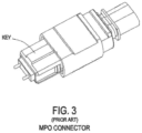
- keying The polarity of an MPO (Multiple-Fiber Push-On/Pull-off) style connector, whether it be method A or method B is determined by the relationship between the fibers and a "key" on the connector body, which is why polarity is sometimes referred to as "keying.”
- Prior art Figure 3 shows a standard prior art MPO connector that has a single fixed key on its body.
- the polarity is set at the time of manufacture.
- the present arrangement overcomes the drawbacks associated with the prior art and provides for a reversible polarity MPO type connector that can be applied without worry of previous installation types or designs.
- the reversible polarity connector reduces installer's and customer's inventory, installation time, and ultimately lowers their cost.
- Such a connector employs a movable key that allows a user to reverse the polarity of the connector without the need to open the connector housing. Additionally, the present connector can be employed in conjunction with a universal connector pin arrangement that also allows a user to push forward or retract the MPO guide pins to assist in accommodating the use of such connectors in both polarities, again without the need for opening the connector.
- the present arrangement provides for a multi-fiber, fiber optic connector, having a housing having a first end for receiving a multi-fiber fiber optic cable and a second end having openings for the fibers from the cable.
- First and second keys for setting the polarity of the fibers within the connector located on opposing sides of the connector.
- the connector has either one of guide pins or guide pin receiving holes for guiding the connection with a second connector.
- the keys are movable between a first active position and a second retracted position, such that when one of the keys is in the first active position, the fibers are presented within the connector in a first polarity and when the second key is in the first active position, the fibers are presented within the connector in a second polarity reversed from the first polarity
- polarity changeable fiber optic assembly comprising:
- the first polarity configuration is a Method A configuration and the second polarity configuration is a Method B configuration.
- the at least two fiber optic connectors are removable from the adapter when the first polarity configuration is to be changed to the second polarity configuration.
- each of the at least two fiber optic connectors comprises a locking arrangement toward a front end of the housing such that the first polarity key and the second polarity key is operable without disassembly of each of the at least two fiber optic connector.
- each of the first polarity key and the second polarity key is adjustable via a respective tab engaged with each ones of the first polarity key and the second polarity key, the tab accessible via an opening defined in the housing.
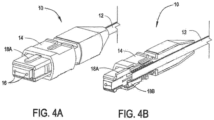
- a connector 10 is provided at the end of a multi fiber cable 12.
- Connector 10 has a housing 14, guide pins/guide pin openings 16 and keys 18A and 18B. It is noted that connector 10 is shown with guide pin openings 16 (female) but all of the features of the present arrangement are equally applicable to male/pins extended connectors 10 as well.
- the "key” sets the order for which the fibers in connector 10 are presented to an additional opposing connector 10. A key that is 'active' is one that is in position to engage with an adapter.
- a key is said to be reversed then it means that the key on the opposite side of the connector (that being the one that was not previously 'active') is now 'active'. If connectors of both regular and reversed active keys are compared, it would be found that the fibers in connector 10 are presented to an opposing connector in opposite order.
- the setting of the key 18 is what sets the polarity (arrangement of fibers from cable 12) for connector 10 from the perspective of an opposing connector.
- key 18A on the top of connector 10 is in a forward extended position.
- key 18A on the top of connector 10 is in a forward extended position with key 18B on the bottom of connector 10 in the retracted position within housing 14.
- Such an arrangement allows for keys 18A and 18B, on both sides of connector 10, to be alternately extended and retracted in order to achieve the desired polarity without disassembling the connector body.
- keys 18A and 18B on top and bottom can be adjusted to determine whether the assembly (cable with a MPO connector on each end) is a 'Method A' or 'Method B' as referred to in the standards.
- the user When a user wants a fiber optic segment to be polarity A, the user simply sets the keys 18A on the tops of connectors 10 on both ends of the segment to the same setting, i.e. both keys 18A forward and active with both keys 18B retracted within housing 14) so that fibers exhibit the same presentation order on both sides of the fiber optic segment.
- one of the keys such as a key 18A on one of the two connectors 10 is retracted into housing 14 and the other key 18B on that same connectors is pushed forward to active. This allows for the polarity of a single assembly or cable to be changed from A to B or B to A.
- Fiber position number is always referenced by holding the key up and looking from left to right.
- two keys 18A/18B on opposing sides of connector 10 With the ability to activate one key or the other, this changes the definition of "up” for that connector.
- two movable keys 18A and 18B on connector 10 and the ability to easily change which key is active (used to determine which way is "up") a user can reverse the order of the fibers presentation on a connector 10 on one end of an assembly only, switching the segment from a Method A to a Method B or vice-versa.
- connector 10 shows top key 18A activated (extended out) and bottom key 18B retracted back into connector 10.
- keys 18A and 18B can be used to change the polarity of connector 10 without the need for opening any part of connector 10, such as housing 14, unlike the prior art configurations.
- FIG. 5 which shows two connectors 10 fitted into an adapter 20.
- Such keys 18A can be operated by simply sliding key 18A forward and backward, or by pressing the key below the surface of the housing and locking arrangement, located towards the front of housing 14 of connector 10.
- Each key 18A and 18B can thus be operated independently with non-specialized tools and without disassembly of the connector, as the tab for keys 18 is accessible through an opening in housing 14. It is noted that in Figure 5 , such a tab for adjusting keys 18, during a connection to another connector 10 via adapter 20, would actually fit within adapter 20.
- the other slide mechanism shown in Figure 5 is related to another feature regarding an adjustable guide pin arrangement discussed in more detail below.
- FIG. 6A One exemplary arrangement for demonstrating the usefulness of connectors 10 is shown in Figures 6A and 6B .
- a first equipment #1 is shown connected to a second equipment #2 using five spans of fiber with MPO type connectors on such spans at four locations (#1 - #4). That is, at each location #1 #4, there is an adapter 20 and two opposing MPO connectors, one for each segment on either side of the adapter.
- the connectors at points #1 through #3 each maintain the same polarity from the prior segment (Method A polarity), and at connector #4 the polarity reverses (Method B polarity) before entering equipment 2 as shown in the figure.
- connector 10 could simply be removed from the adapter 20 at location #2 have the appropriate key 18 retracted/moved forward, and reinserted into the adapter as shown in Figure 6B , changed from Method A to Method B polarity.
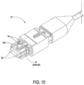
- connector 10 in addition to connector 10 being a reversible polarity connector 10 using keys 18A and 18B as explained above, such connectors 10 may also have a retractable guide pin arrangement 50 so that connector 10, in addition to having reversible polarity also can exchange between male (extended) and female (retracted) guide pin configurations.
- connector 10 has a guide pin arrangement 50 shown in the extended male configuration.
- Guide pin arrangement 50 includes an attached retraction tabs 52 (one opposing side not shown) located on either side of the connector.
- connector 10 has the same retractable guide pin arrangement 50 shown in the extended male configuration.
- guide pin arrangement 50 includes attached retraction tabs 52B located on the top of connector 10.
- connector 10 again has the same retractable guide pin arrangement 50.
- guide pin arrangement 50 includes a single attached retraction tab 52C located on the top of connector 10 in between a bifurcated arrangement of tab(s) 18C to change the polarity of key 18A.
- connector 10 has the same retractable guide pin arrangement 50.
- guide pin arrangement 50 are spring biased via biasing springs 51 (internal) and held in position using pin locks 54 on top of connector 10.
Landscapes
- Physics & Mathematics (AREA)
- General Physics & Mathematics (AREA)
- Optics & Photonics (AREA)
- Details Of Connecting Devices For Male And Female Coupling (AREA)
- Mechanical Coupling Of Light Guides (AREA)
Applications Claiming Priority (4)
| Application Number | Priority Date | Filing Date | Title |
|---|---|---|---|
| US14/319,132 US9829645B2 (en) | 2014-06-30 | 2014-06-30 | Reversible polarity MPO fiber optic connector |
| EP15770633.4A EP3161535B1 (de) | 2014-06-30 | 2015-06-04 | Umpolbarer faseroptischer mpo-stecker |
| PCT/IB2015/001127 WO2016001744A1 (en) | 2014-06-30 | 2015-06-04 | Reversible polarity mpo fiber optic connector |
| EP20188175.2A EP3761091B1 (de) | 2014-06-30 | 2015-06-04 | Umpolbarer faseroptischer mpo-stecker |
Related Parent Applications (2)
| Application Number | Title | Priority Date | Filing Date |
|---|---|---|---|
| EP20188175.2A Division EP3761091B1 (de) | 2014-06-30 | 2015-06-04 | Umpolbarer faseroptischer mpo-stecker |
| EP15770633.4A Division EP3161535B1 (de) | 2014-06-30 | 2015-06-04 | Umpolbarer faseroptischer mpo-stecker |
Publications (3)
| Publication Number | Publication Date |
|---|---|
| EP4279970A2 true EP4279970A2 (de) | 2023-11-22 |
| EP4279970A3 EP4279970A3 (de) | 2024-02-07 |
| EP4279970B1 EP4279970B1 (de) | 2026-04-08 |
Family
ID=54197000
Family Applications (3)
| Application Number | Title | Priority Date | Filing Date |
|---|---|---|---|
| EP20188175.2A Active EP3761091B1 (de) | 2014-06-30 | 2015-06-04 | Umpolbarer faseroptischer mpo-stecker |
| EP23197931.1A Active EP4279970B1 (de) | 2014-06-30 | 2015-06-04 | Mpo-glasfaserverbinder mit umkehrbarer polarität |
| EP15770633.4A Active EP3161535B1 (de) | 2014-06-30 | 2015-06-04 | Umpolbarer faseroptischer mpo-stecker |
Family Applications Before (1)
| Application Number | Title | Priority Date | Filing Date |
|---|---|---|---|
| EP20188175.2A Active EP3761091B1 (de) | 2014-06-30 | 2015-06-04 | Umpolbarer faseroptischer mpo-stecker |
Family Applications After (1)
| Application Number | Title | Priority Date | Filing Date |
|---|---|---|---|
| EP15770633.4A Active EP3161535B1 (de) | 2014-06-30 | 2015-06-04 | Umpolbarer faseroptischer mpo-stecker |
Country Status (5)
| Country | Link |
|---|---|
| US (6) | US9829645B2 (de) |
| EP (3) | EP3761091B1 (de) |
| CN (2) | CN106471409B (de) |
| CA (1) | CA2950522C (de) |
| WO (1) | WO2016001744A1 (de) |
Families Citing this family (74)
| Publication number | Priority date | Publication date | Assignee | Title |
|---|---|---|---|---|
| US10031296B2 (en) | 2013-07-03 | 2018-07-24 | Nexans | Reversible polarity MPO fiber optic connector with a removable key |
| US9829645B2 (en) | 2014-06-30 | 2017-11-28 | Nexans | Reversible polarity MPO fiber optic connector |
| US9658409B2 (en) | 2015-03-03 | 2017-05-23 | Senko Advanced Components, Inc. | Optical fiber connector with changeable polarity |
| US9684139B2 (en) | 2015-05-29 | 2017-06-20 | Senko Advanced Components, Inc. | Optical fiber connector with changeable gender |
| USD800660S1 (en) * | 2015-06-05 | 2017-10-24 | Corning Optical Communications LLC | Fiber optic connector |
| USD800659S1 (en) * | 2015-06-05 | 2017-10-24 | Corning Optical Communications LLC | Fiber optic connector |
| US10712507B2 (en) | 2015-12-19 | 2020-07-14 | US Conec, Ltd | Field changeable fiber optic connector polarity keying |
| US9880361B2 (en) | 2015-12-19 | 2018-01-30 | Us Conec Ltd. | Field changeable fiber optic connector polarity keying with color coding |
| US10158194B2 (en) | 2016-01-15 | 2018-12-18 | Senko Advanced Components, Inc. | Narrow width adapters and connectors with spring loaded remote release |
| EP3430452B1 (de) | 2016-03-16 | 2022-03-09 | Berk-Tek LLC | Mpo-glasfaserstecker mit reversibler polarität und entfernbarem schlüssel |
| US9726830B1 (en) | 2016-06-28 | 2017-08-08 | Senko Advanced Components, Inc. | Connector and adapter system for two-fiber mechanical transfer type ferrule |
| US9939589B2 (en) * | 2016-07-08 | 2018-04-10 | Senko Advanced Components, Inc. | Polarity changeable connector |
| CN106154432A (zh) * | 2016-08-23 | 2016-11-23 | 深圳市特发信息光网科技股份有限公司 | 一种组装防呆式lc型活动连接器 |
| US10921529B2 (en) * | 2016-11-13 | 2021-02-16 | USConec, Ltd | Long push pull sleeve indicating orientation |
| US10228521B2 (en) | 2016-12-05 | 2019-03-12 | Senko Advanced Components, Inc. | Narrow width adapters and connectors with modular latching arm |
| US10078188B1 (en) | 2016-12-05 | 2018-09-18 | Senko Advanced Components, Inc. | Springless push/pull fiber optic connector |
| US10185100B2 (en) | 2017-01-30 | 2019-01-22 | Senko Advanced Components, Inc | Modular connector and adapter assembly using a removable anchor device |
| US10416394B2 (en) | 2017-01-30 | 2019-09-17 | Senko Advanced Components, Inc. | Fiber optic receptacle with integrated device therein |
| US11333836B2 (en) | 2017-01-30 | 2022-05-17 | Senko Advanced Components, Inc. | Adapter for optical connectors |
| US10725248B2 (en) | 2017-01-30 | 2020-07-28 | Senko Advanced Components, Inc. | Fiber optic receptacle with integrated device therein incorporating a behind-the-wall fiber optic receptacle |
| US10444444B2 (en) | 2017-01-30 | 2019-10-15 | Senko Advanced Components, Inc. | Remote release tab connector assembly |
| EP3574356A4 (de) | 2017-01-30 | 2020-08-19 | Senko Advanced Components Inc. | Optische verbinder mit reversibler polarität |
| US10359583B2 (en) | 2017-04-07 | 2019-07-23 | Senko Advanced Components, Inc. | Behind the wall optical connector with reduced components |
| US10209461B2 (en) | 2017-04-07 | 2019-02-19 | Senko Advanced Components | Behind the wall optical connector with reduced components |
| US10989884B2 (en) | 2017-04-07 | 2021-04-27 | Senko Advanced Components, Inc. | Behind the wall optical connector with reduced components |
| US10754098B2 (en) | 2017-04-07 | 2020-08-25 | Senko Advanced Components, Inc. | Behind the wall optical connector with reduced components |
| US10718910B2 (en) | 2017-05-03 | 2020-07-21 | Senko Advanced Components, Inc | Field terminated ruggedized fiber optic connector system |
| US10146016B1 (en) | 2017-05-10 | 2018-12-04 | Senko Advanced Components, Inc | MPO micro-latchlock connector |
| US10401576B2 (en) | 2017-05-10 | 2019-09-03 | Senko Advanced Components, Inc. | MPO micro-latch-lock connector |
| US10295759B2 (en) | 2017-05-18 | 2019-05-21 | Senko Advanced Components, Inc. | Optical connector with forward-biasing projections |
| US10359576B2 (en) | 2017-06-15 | 2019-07-23 | Senko Advanced Components, Inc. | SC low profile connector with optional boot |
| US10281668B2 (en) | 2017-07-14 | 2019-05-07 | Senko Advanced Components, Inc. | Ultra-small form factor optical connectors |
| US12001064B2 (en) | 2017-07-14 | 2024-06-04 | Senko Advanced Components, Inc. | Small form factor fiber optic connector with multi-purpose boot |
| US10718911B2 (en) | 2017-08-24 | 2020-07-21 | Senko Advanced Components, Inc. | Ultra-small form factor optical connectors using a push-pull boot receptacle release |
| US11822133B2 (en) | 2017-07-14 | 2023-11-21 | Senko Advanced Components, Inc. | Ultra-small form factor optical connector and adapter |
| US10641972B2 (en) | 2017-08-17 | 2020-05-05 | Senko Advanced Components, Inc | Anti-jam alignment sleeve holder or connector housing for a ferrule assembly |
| CN107590059B (zh) * | 2017-09-20 | 2021-04-09 | 郑州云海信息技术有限公司 | 一种存储控制器的安装系统及方法 |
| CN107577013A (zh) * | 2017-09-30 | 2018-01-12 | 上海传输线研究所(中国电子科技集团公司第二十三研究所) | 一种穿舱用光纤连接器及光纤连接器穿舱组件 |
| US10444442B2 (en) | 2017-11-03 | 2019-10-15 | Senko Advanced Components, Inc. | MPO optical fiber connector |
| US11002923B2 (en) | 2017-11-21 | 2021-05-11 | Senko Advanced Components, Inc. | Fiber optic connector with cable boot release having a two-piece clip assembly |
| CN115201974B (zh) * | 2017-12-19 | 2024-04-30 | 美国康涅克有限公司 | 具有推拉极性机构和载体的微型双工连接器 |
| US11112566B2 (en) | 2018-03-19 | 2021-09-07 | Senko Advanced Components, Inc. | Removal tool for removing a plural of micro optical connectors from an adapter interface |
| EP3776038B1 (de) | 2018-03-28 | 2024-07-03 | Senko Advanced Components Inc. | Faseroptischer steckverbinder mit kleinem formfaktor und multifunktionalem knickschutz |
| US11041993B2 (en) | 2018-04-19 | 2021-06-22 | Senko Advanced Components, Inc. | Fiber optic adapter with removable insert for polarity change and removal tool for the same |
| US10921528B2 (en) | 2018-06-07 | 2021-02-16 | Senko Advanced Components, Inc. | Dual spring multi-fiber optic connector |
| ES3016433T3 (en) * | 2018-06-19 | 2025-05-09 | Commscope Technologies Llc | Multi-fiber fiber optic connector having enhanced functionality |
| CN112088327A (zh) | 2018-07-15 | 2020-12-15 | 扇港元器件股份有限公司 | 超小型光学连接器和适配器 |
| US10444441B1 (en) | 2018-08-10 | 2019-10-15 | Senko Advanced Components, Inc. | Pivotable housing for a fiber optic connector |
| US11073664B2 (en) | 2018-08-13 | 2021-07-27 | Senko Advanced Components, Inc. | Cable boot assembly for releasing fiber optic connector from a receptacle |
| TWM569855U (zh) * | 2018-08-16 | 2018-11-11 | 大陸商深圳望得源科技有限公司 | The optical fiber connector |
| CN112955797B (zh) | 2018-09-12 | 2022-11-11 | 扇港元器件股份有限公司 | 具有用于利用缆线护套将连接器从插座释放的夹式推/拉舌片的lc型连接器 |
| US10921530B2 (en) | 2018-09-12 | 2021-02-16 | Senko Advanced Components, Inc. | LC type connector with push/pull assembly for releasing connector from a receptacle using a cable boot |
| US10921531B2 (en) | 2018-09-12 | 2021-02-16 | Senko Advanced Components, Inc. | LC type connector with push/pull assembly for releasing connector from a receptacle using a cable boot |
| US11806831B2 (en) | 2018-11-21 | 2023-11-07 | Senko Advanced Components, Inc. | Fixture and method for polishing fiber optic connector ferrules |
| US11175464B2 (en) | 2018-11-25 | 2021-11-16 | Senko Advanced Components, Inc. | Open ended spring body for use in an optical fiber connector |
| WO2020118176A1 (en) * | 2018-12-06 | 2020-06-11 | Senko Advanced Components, Inc | Ultra-small form factor optical connectors with polarity change and method of use |
| US11579379B2 (en) | 2019-03-28 | 2023-02-14 | Senko Advanced Components, Inc. | Fiber optic adapter assembly |
| US12038613B2 (en) | 2019-03-28 | 2024-07-16 | Senko Advanced Components, Inc. | Behind-the-wall optical connector and assembly of the same |
| WO2020214762A1 (en) | 2019-04-16 | 2020-10-22 | Corning Research & Development Corporation | Preconnectorized cable assemblies for indoor/outdoor/datacenter applications |
| US11340406B2 (en) | 2019-04-19 | 2022-05-24 | Senko Advanced Components, Inc. | Small form factor fiber optic connector with resilient latching mechanism for securing within a hook-less receptacle |
| CN114026480B (zh) | 2019-06-13 | 2023-05-26 | 扇港元器件有限公司 | 用于从插座端口释放光纤连接器的杆驱动闩锁臂和使用方法 |
| CN114600018B (zh) | 2019-07-23 | 2024-04-09 | 扇港元器件有限公司 | 用于接收与插芯组件相对的光纤连接器的超小型插座 |
| CN110376684B (zh) * | 2019-07-31 | 2024-10-29 | 新确精密科技(深圳)有限公司 | 一种极性可变的光纤连接器 |
| US11353664B1 (en) | 2019-08-21 | 2022-06-07 | Senko Advanced Components, Inc. | Fiber optic connector |
| CN114787677A (zh) | 2019-11-13 | 2022-07-22 | 扇港元器件有限公司 | 光纤连接器 |
| BR112022007939A2 (pt) | 2019-11-20 | 2022-07-12 | Senko Advanced Components Inc | Conector de fibra óptica de polaridade reversível |
| CN111552036B (zh) * | 2020-06-09 | 2025-06-27 | 江苏宇特光电科技股份有限公司 | 一种变极性连接器 |
| US12047117B2 (en) | 2020-07-30 | 2024-07-23 | Exfo Inc. | Optical-fiber device for one-cord reference optical power loss measurement |
| WO2022046624A1 (en) * | 2020-08-28 | 2022-03-03 | Commscope Technologies Llc | Multi-fiber semi-permanent splicing systems |
| US11841289B2 (en) * | 2020-11-11 | 2023-12-12 | Lifodas, Uab | Polarity receive module |
| US12523821B2 (en) | 2021-04-08 | 2026-01-13 | Commscope Technologies Llc | Telecommunications connector with latch release mechanism |
| US20250116827A1 (en) * | 2022-01-10 | 2025-04-10 | Commscope Technologies Llc | Connectivity system integrating keying elements |
| US12442719B2 (en) | 2022-01-19 | 2025-10-14 | Exfo Inc. | Duplex optical power loss measurement using an adaptor device |
| US20240039224A1 (en) * | 2022-07-29 | 2024-02-01 | Methode Electronics, Inc. | Single-pair ethernet pluggable module |
Family Cites Families (25)
| Publication number | Priority date | Publication date | Assignee | Title |
|---|---|---|---|---|
| DE3601115A1 (de) * | 1986-01-16 | 1987-07-23 | Fraunhofer Ges Forschung | Unverwechselbare steckverbindung |
| JPH02146511A (ja) | 1988-11-29 | 1990-06-05 | Nippon Telegr & Teleph Corp <Ntt> | 光ファイバ切替コネクタ |
| US4979792A (en) * | 1989-08-21 | 1990-12-25 | Amp Incorporated | Means for keeping keying elements with a connector assembly |
| US5041025A (en) * | 1990-01-31 | 1991-08-20 | Thomas & Betts Corporation | Interconnectable components employing a multi-positionable key |
| US5167542A (en) * | 1990-01-31 | 1992-12-01 | Thomas & Betts Corporation | Interconnectable components employing a multi-positionable key |
| US5335301A (en) * | 1993-05-05 | 1994-08-02 | Methode Electronics, Inc. | Fiber optic connector with sliding key |
| US5521997A (en) * | 1995-02-28 | 1996-05-28 | The Whitaker Corporation | Rotatably polarizing keying element for a polarized connector |
| EP0800100A1 (de) * | 1996-04-04 | 1997-10-08 | US Conec Ltd | Muffenanordnung zum Einführen eines Führungszapfen ohne Spiel |
| US6371658B2 (en) | 1998-02-24 | 2002-04-16 | Jds Fitel Inc. | Tuned multiple fiber optic connector |
| US6464408B1 (en) * | 1998-12-28 | 2002-10-15 | Computer Crafts, Inc. | Fiber optic connectors |
| US6634796B2 (en) * | 1999-06-30 | 2003-10-21 | Corning Cable Systems Llc | Polarity reversal for fiber optic connections |
| JP2001116955A (ja) * | 1999-08-09 | 2001-04-27 | Sumitomo Electric Ind Ltd | 光コネクタ及び光結合構造 |
| US6364537B1 (en) * | 2000-02-08 | 2002-04-02 | The Siemon Company | Dual polarity fiber optic adapter |
| JP4158895B2 (ja) | 2001-11-08 | 2008-10-01 | 古河電気工業株式会社 | 機能性光ファイバコネクタ |
| US8046030B2 (en) | 2005-07-29 | 2011-10-25 | Sony Ericsson Mobile Communications Ab | Methods, devices and computer program products for operating mobile devices responsive to user input through movement thereof |
| JP5735248B2 (ja) * | 2010-09-30 | 2015-06-17 | 株式会社フジクラ | 光コネクタ、光コネクタの接続方法、コネクタアダプタ、光線路、光通信システム |
| US8636424B2 (en) * | 2010-10-22 | 2014-01-28 | Panduit Corp. | Optical communication connector |
| US8676022B2 (en) * | 2012-04-13 | 2014-03-18 | Corning Cable Systems Llc | Adapter for fiber optic connectors |
| US8770863B2 (en) * | 2012-06-04 | 2014-07-08 | Corning Cable Systems Llc | Multi-fiber fiber-optic connector with switchable polarity key |
| US9417406B2 (en) | 2012-08-31 | 2016-08-16 | Corning Cable Systems Llc | Cable assemblies and optical connector assemblies employing a unitary alignment pin and translating element |
| US10031296B2 (en) * | 2013-07-03 | 2018-07-24 | Nexans | Reversible polarity MPO fiber optic connector with a removable key |
| US9046660B2 (en) * | 2013-07-03 | 2015-06-02 | Nexans | Fiber optic connector |
| US9310569B2 (en) * | 2014-02-21 | 2016-04-12 | Alliance Fiber Optic Products, Inc. | Reconfigurable fiber optic adapter |
| US9829645B2 (en) * | 2014-06-30 | 2017-11-28 | Nexans | Reversible polarity MPO fiber optic connector |
| EP3430452B1 (de) * | 2016-03-16 | 2022-03-09 | Berk-Tek LLC | Mpo-glasfaserstecker mit reversibler polarität und entfernbarem schlüssel |
-
2014
- 2014-06-30 US US14/319,132 patent/US9829645B2/en active Active
-
2015
- 2015-06-04 EP EP20188175.2A patent/EP3761091B1/de active Active
- 2015-06-04 CN CN201580036051.2A patent/CN106471409B/zh active Active
- 2015-06-04 CA CA2950522A patent/CA2950522C/en active Active
- 2015-06-04 EP EP23197931.1A patent/EP4279970B1/de active Active
- 2015-06-04 EP EP15770633.4A patent/EP3161535B1/de active Active
- 2015-06-04 WO PCT/IB2015/001127 patent/WO2016001744A1/en not_active Ceased
- 2015-06-04 CN CN201810917393.0A patent/CN109061808B/zh active Active
-
2017
- 2017-11-01 US US15/800,883 patent/US10495823B2/en active Active
-
2019
- 2019-10-02 US US16/591,590 patent/US10690861B2/en active Active
-
2020
- 2020-05-26 US US16/883,156 patent/US11256038B2/en active Active
-
2022
- 2022-02-15 US US17/671,653 patent/US11662529B2/en active Active
-
2023
- 2023-05-29 US US18/202,994 patent/US12181717B2/en active Active
Also Published As
| Publication number | Publication date |
|---|---|
| US11662529B2 (en) | 2023-05-30 |
| CN109061808B (zh) | 2021-03-12 |
| CN106471409A (zh) | 2017-03-01 |
| EP3161535A1 (de) | 2017-05-03 |
| EP3761091B1 (de) | 2023-09-20 |
| CN109061808A (zh) | 2018-12-21 |
| US20180128987A1 (en) | 2018-05-10 |
| US20220171141A1 (en) | 2022-06-02 |
| US9829645B2 (en) | 2017-11-28 |
| CA2950522A1 (en) | 2016-01-07 |
| US12181717B2 (en) | 2024-12-31 |
| EP4279970B1 (de) | 2026-04-08 |
| CA2950522C (en) | 2023-01-24 |
| EP4279970A3 (de) | 2024-02-07 |
| EP3161535B1 (de) | 2020-08-19 |
| US11256038B2 (en) | 2022-02-22 |
| EP3761091A1 (de) | 2021-01-06 |
| US10690861B2 (en) | 2020-06-23 |
| US20200033539A1 (en) | 2020-01-30 |
| US20150378113A1 (en) | 2015-12-31 |
| US10495823B2 (en) | 2019-12-03 |
| WO2016001744A1 (en) | 2016-01-07 |
| CN106471409B (zh) | 2018-08-28 |
| US20200284995A1 (en) | 2020-09-10 |
| US20230314724A1 (en) | 2023-10-05 |
Similar Documents
| Publication | Publication Date | Title |
|---|---|---|
| US11662529B2 (en) | Reversible polarity MPO fiber optic connector | |
| US10031296B2 (en) | Reversible polarity MPO fiber optic connector with a removable key | |
| US11822132B2 (en) | Optical communications connectors | |
| US9046660B2 (en) | Fiber optic connector | |
| US10712506B2 (en) | Field changeable fiber optic connector polarity keying with color coding | |
| US10627580B2 (en) | Reversible polarity MPO fiber optic connector with a removable key | |
| US20250060541A1 (en) | Optical Communications Connectors |
Legal Events
| Date | Code | Title | Description |
|---|---|---|---|
| PUAI | Public reference made under article 153(3) epc to a published international application that has entered the european phase |
Free format text: ORIGINAL CODE: 0009012 |
|
| STAA | Information on the status of an ep patent application or granted ep patent |
Free format text: STATUS: THE APPLICATION HAS BEEN PUBLISHED |
|
| AC | Divisional application: reference to earlier application |
Ref document number: 3161535 Country of ref document: EP Kind code of ref document: P Ref document number: 3761091 Country of ref document: EP Kind code of ref document: P |
|
| AK | Designated contracting states |
Kind code of ref document: A2 Designated state(s): AL AT BE BG CH CY CZ DE DK EE ES FI FR GB GR HR HU IE IS IT LI LT LU LV MC MK MT NL NO PL PT RO RS SE SI SK SM TR |
|
| PUAL | Search report despatched |
Free format text: ORIGINAL CODE: 0009013 |
|
| AK | Designated contracting states |
Kind code of ref document: A3 Designated state(s): AL AT BE BG CH CY CZ DE DK EE ES FI FR GB GR HR HU IE IS IT LI LT LU LV MC MK MT NL NO PL PT RO RS SE SI SK SM TR |
|
| RIC1 | Information provided on ipc code assigned before grant |
Ipc: G02B 6/38 20060101AFI20240102BHEP |
|
| P01 | Opt-out of the competence of the unified patent court (upc) registered |
Free format text: CASE NUMBER: APP_37223/2024 Effective date: 20240621 |
|
| STAA | Information on the status of an ep patent application or granted ep patent |
Free format text: STATUS: REQUEST FOR EXAMINATION WAS MADE |
|
| 17P | Request for examination filed |
Effective date: 20240805 |
|
| RBV | Designated contracting states (corrected) |
Designated state(s): AL AT BE BG CH CY CZ DE DK EE ES FI FR GB GR HR HU IE IS IT LI LT LU LV MC MK MT NL NO PL PT RO RS SE SI SK SM TR |
|
| GRAP | Despatch of communication of intention to grant a patent |
Free format text: ORIGINAL CODE: EPIDOSNIGR1 |
|
| STAA | Information on the status of an ep patent application or granted ep patent |
Free format text: STATUS: GRANT OF PATENT IS INTENDED |
|
| INTG | Intention to grant announced |
Effective date: 20251105 |
|
| GRAS | Grant fee paid |
Free format text: ORIGINAL CODE: EPIDOSNIGR3 |
|
| GRAA | (expected) grant |
Free format text: ORIGINAL CODE: 0009210 |
|
| STAA | Information on the status of an ep patent application or granted ep patent |
Free format text: STATUS: THE PATENT HAS BEEN GRANTED |
|
| AC | Divisional application: reference to earlier application |
Ref document number: 3761091 Country of ref document: EP Kind code of ref document: P Ref document number: 3161535 Country of ref document: EP Kind code of ref document: P |
|
| AK | Designated contracting states |
Kind code of ref document: B1 Designated state(s): AL AT BE BG CH CY CZ DE DK EE ES FI FR GB GR HR HU IE IS IT LI LT LU LV MC MK MT NL NO PL PT RO RS SE SI SK SM TR |
|
| REG | Reference to a national code |
Ref country code: CH Ref legal event code: F10 Free format text: ST27 STATUS EVENT CODE: U-0-0-F10-F00 (AS PROVIDED BY THE NATIONAL OFFICE) Effective date: 20260408 Ref country code: GB Ref legal event code: FG4D |
|
| REG | Reference to a national code |
Ref country code: DE Ref legal event code: R096 Ref document number: 602015093241 Country of ref document: DE |