EP4283733A1 - Batterie secondaire de type poche et son procédé de fabrication - Google Patents
Batterie secondaire de type poche et son procédé de fabrication Download PDFInfo
- Publication number
- EP4283733A1 EP4283733A1 EP23740438.9A EP23740438A EP4283733A1 EP 4283733 A1 EP4283733 A1 EP 4283733A1 EP 23740438 A EP23740438 A EP 23740438A EP 4283733 A1 EP4283733 A1 EP 4283733A1
- Authority
- EP
- European Patent Office
- Prior art keywords
- pouch
- average thickness
- resin layer
- area
- unsealed area
- Prior art date
- Legal status (The legal status is an assumption and is not a legal conclusion. Google has not performed a legal analysis and makes no representation as to the accuracy of the status listed.)
- Pending
Links
Images




Classifications
-
- H—ELECTRICITY
- H01—ELECTRIC ELEMENTS
- H01M—PROCESSES OR MEANS, e.g. BATTERIES, FOR THE DIRECT CONVERSION OF CHEMICAL ENERGY INTO ELECTRICAL ENERGY
- H01M50/00—Constructional details or processes of manufacture of the non-active parts of electrochemical cells other than fuel cells, e.g. hybrid cells
- H01M50/10—Primary casings; Jackets or wrappings
- H01M50/102—Primary casings; Jackets or wrappings characterised by their shape or physical structure
- H01M50/105—Pouches or flexible bags
-
- H—ELECTRICITY
- H01—ELECTRIC ELEMENTS
- H01M—PROCESSES OR MEANS, e.g. BATTERIES, FOR THE DIRECT CONVERSION OF CHEMICAL ENERGY INTO ELECTRICAL ENERGY
- H01M50/00—Constructional details or processes of manufacture of the non-active parts of electrochemical cells other than fuel cells, e.g. hybrid cells
- H01M50/10—Primary casings; Jackets or wrappings
- H01M50/116—Primary casings; Jackets or wrappings characterised by the material
- H01M50/124—Primary casings; Jackets or wrappings characterised by the material having a layered structure
- H01M50/126—Primary casings; Jackets or wrappings characterised by the material having a layered structure comprising three or more layers
- H01M50/129—Primary casings; Jackets or wrappings characterised by the material having a layered structure comprising three or more layers with two or more layers of only organic material
-
- B—PERFORMING OPERATIONS; TRANSPORTING
- B29—WORKING OF PLASTICS; WORKING OF SUBSTANCES IN A PLASTIC STATE IN GENERAL
- B29C—SHAPING OR JOINING OF PLASTICS; SHAPING OF MATERIAL IN A PLASTIC STATE, NOT OTHERWISE PROVIDED FOR; AFTER-TREATMENT OF THE SHAPED PRODUCTS, e.g. REPAIRING
- B29C65/00—Joining or sealing of preformed parts, e.g. welding of plastics materials; Apparatus therefor
- B29C65/02—Joining or sealing of preformed parts, e.g. welding of plastics materials; Apparatus therefor by heating, with or without pressure
- B29C65/18—Joining or sealing of preformed parts, e.g. welding of plastics materials; Apparatus therefor by heating, with or without pressure using heated tools
-
- B—PERFORMING OPERATIONS; TRANSPORTING
- B29—WORKING OF PLASTICS; WORKING OF SUBSTANCES IN A PLASTIC STATE IN GENERAL
- B29C—SHAPING OR JOINING OF PLASTICS; SHAPING OF MATERIAL IN A PLASTIC STATE, NOT OTHERWISE PROVIDED FOR; AFTER-TREATMENT OF THE SHAPED PRODUCTS, e.g. REPAIRING
- B29C66/00—General aspects of processes or apparatus for joining preformed parts
- B29C66/40—General aspects of joining substantially flat articles, e.g. plates, sheets or web-like materials; Making flat seams in tubular or hollow articles; Joining single elements to substantially flat surfaces
- B29C66/41—Joining substantially flat articles ; Making flat seams in tubular or hollow articles
- B29C66/43—Joining a relatively small portion of the surface of said articles
- B29C66/433—Casing-in, i.e. enclosing an element between two sheets by an outlined seam
-
- H—ELECTRICITY
- H01—ELECTRIC ELEMENTS
- H01M—PROCESSES OR MEANS, e.g. BATTERIES, FOR THE DIRECT CONVERSION OF CHEMICAL ENERGY INTO ELECTRICAL ENERGY
- H01M10/00—Secondary cells; Manufacture thereof
- H01M10/04—Construction or manufacture in general
-
- H—ELECTRICITY
- H01—ELECTRIC ELEMENTS
- H01M—PROCESSES OR MEANS, e.g. BATTERIES, FOR THE DIRECT CONVERSION OF CHEMICAL ENERGY INTO ELECTRICAL ENERGY
- H01M10/00—Secondary cells; Manufacture thereof
- H01M10/04—Construction or manufacture in general
- H01M10/0404—Machines for assembling batteries
-
- H—ELECTRICITY
- H01—ELECTRIC ELEMENTS
- H01M—PROCESSES OR MEANS, e.g. BATTERIES, FOR THE DIRECT CONVERSION OF CHEMICAL ENERGY INTO ELECTRICAL ENERGY
- H01M10/00—Secondary cells; Manufacture thereof
- H01M10/04—Construction or manufacture in general
- H01M10/0436—Small-sized flat cells or batteries for portable equipment
-
- H—ELECTRICITY
- H01—ELECTRIC ELEMENTS
- H01M—PROCESSES OR MEANS, e.g. BATTERIES, FOR THE DIRECT CONVERSION OF CHEMICAL ENERGY INTO ELECTRICAL ENERGY
- H01M10/00—Secondary cells; Manufacture thereof
- H01M10/04—Construction or manufacture in general
- H01M10/049—Processes for forming or storing electrodes in the battery container
-
- H—ELECTRICITY
- H01—ELECTRIC ELEMENTS
- H01M—PROCESSES OR MEANS, e.g. BATTERIES, FOR THE DIRECT CONVERSION OF CHEMICAL ENERGY INTO ELECTRICAL ENERGY
- H01M10/00—Secondary cells; Manufacture thereof
- H01M10/05—Accumulators with non-aqueous electrolyte
- H01M10/058—Construction or manufacture
-
- H—ELECTRICITY
- H01—ELECTRIC ELEMENTS
- H01M—PROCESSES OR MEANS, e.g. BATTERIES, FOR THE DIRECT CONVERSION OF CHEMICAL ENERGY INTO ELECTRICAL ENERGY
- H01M50/00—Constructional details or processes of manufacture of the non-active parts of electrochemical cells other than fuel cells, e.g. hybrid cells
- H01M50/10—Primary casings; Jackets or wrappings
- H01M50/116—Primary casings; Jackets or wrappings characterised by the material
- H01M50/117—Inorganic material
- H01M50/119—Metals
-
- H—ELECTRICITY
- H01—ELECTRIC ELEMENTS
- H01M—PROCESSES OR MEANS, e.g. BATTERIES, FOR THE DIRECT CONVERSION OF CHEMICAL ENERGY INTO ELECTRICAL ENERGY
- H01M50/00—Constructional details or processes of manufacture of the non-active parts of electrochemical cells other than fuel cells, e.g. hybrid cells
- H01M50/10—Primary casings; Jackets or wrappings
- H01M50/116—Primary casings; Jackets or wrappings characterised by the material
- H01M50/121—Organic material
-
- H—ELECTRICITY
- H01—ELECTRIC ELEMENTS
- H01M—PROCESSES OR MEANS, e.g. BATTERIES, FOR THE DIRECT CONVERSION OF CHEMICAL ENERGY INTO ELECTRICAL ENERGY
- H01M50/00—Constructional details or processes of manufacture of the non-active parts of electrochemical cells other than fuel cells, e.g. hybrid cells
- H01M50/10—Primary casings; Jackets or wrappings
- H01M50/116—Primary casings; Jackets or wrappings characterised by the material
- H01M50/124—Primary casings; Jackets or wrappings characterised by the material having a layered structure
- H01M50/126—Primary casings; Jackets or wrappings characterised by the material having a layered structure comprising three or more layers
-
- H—ELECTRICITY
- H01—ELECTRIC ELEMENTS
- H01M—PROCESSES OR MEANS, e.g. BATTERIES, FOR THE DIRECT CONVERSION OF CHEMICAL ENERGY INTO ELECTRICAL ENERGY
- H01M50/00—Constructional details or processes of manufacture of the non-active parts of electrochemical cells other than fuel cells, e.g. hybrid cells
- H01M50/10—Primary casings; Jackets or wrappings
- H01M50/131—Primary casings; Jackets or wrappings characterised by physical properties, e.g. gas permeability, size or heat resistance
-
- H—ELECTRICITY
- H01—ELECTRIC ELEMENTS
- H01M—PROCESSES OR MEANS, e.g. BATTERIES, FOR THE DIRECT CONVERSION OF CHEMICAL ENERGY INTO ELECTRICAL ENERGY
- H01M50/00—Constructional details or processes of manufacture of the non-active parts of electrochemical cells other than fuel cells, e.g. hybrid cells
- H01M50/10—Primary casings; Jackets or wrappings
- H01M50/131—Primary casings; Jackets or wrappings characterised by physical properties, e.g. gas permeability, size or heat resistance
- H01M50/133—Thickness
-
- H—ELECTRICITY
- H01—ELECTRIC ELEMENTS
- H01M—PROCESSES OR MEANS, e.g. BATTERIES, FOR THE DIRECT CONVERSION OF CHEMICAL ENERGY INTO ELECTRICAL ENERGY
- H01M50/00—Constructional details or processes of manufacture of the non-active parts of electrochemical cells other than fuel cells, e.g. hybrid cells
- H01M50/10—Primary casings; Jackets or wrappings
- H01M50/172—Arrangements of electric connectors penetrating the casing
- H01M50/174—Arrangements of electric connectors penetrating the casing adapted for the shape of the cells
- H01M50/178—Arrangements of electric connectors penetrating the casing adapted for the shape of the cells for pouch or flexible bag cells
-
- H—ELECTRICITY
- H01—ELECTRIC ELEMENTS
- H01M—PROCESSES OR MEANS, e.g. BATTERIES, FOR THE DIRECT CONVERSION OF CHEMICAL ENERGY INTO ELECTRICAL ENERGY
- H01M50/00—Constructional details or processes of manufacture of the non-active parts of electrochemical cells other than fuel cells, e.g. hybrid cells
- H01M50/10—Primary casings; Jackets or wrappings
- H01M50/183—Sealing members
-
- B—PERFORMING OPERATIONS; TRANSPORTING
- B29—WORKING OF PLASTICS; WORKING OF SUBSTANCES IN A PLASTIC STATE IN GENERAL
- B29L—INDEXING SCHEME ASSOCIATED WITH SUBCLASS B29C, RELATING TO PARTICULAR ARTICLES
- B29L2031/00—Other particular articles
- B29L2031/712—Containers; Packaging elements or accessories, Packages
- B29L2031/7146—Battery-cases
-
- Y—GENERAL TAGGING OF NEW TECHNOLOGICAL DEVELOPMENTS; GENERAL TAGGING OF CROSS-SECTIONAL TECHNOLOGIES SPANNING OVER SEVERAL SECTIONS OF THE IPC; TECHNICAL SUBJECTS COVERED BY FORMER USPC CROSS-REFERENCE ART COLLECTIONS [XRACs] AND DIGESTS
- Y02—TECHNOLOGIES OR APPLICATIONS FOR MITIGATION OR ADAPTATION AGAINST CLIMATE CHANGE
- Y02E—REDUCTION OF GREENHOUSE GAS [GHG] EMISSIONS, RELATED TO ENERGY GENERATION, TRANSMISSION OR DISTRIBUTION
- Y02E60/00—Enabling technologies; Technologies with a potential or indirect contribution to GHG emissions mitigation
- Y02E60/10—Energy storage using batteries
-
- Y—GENERAL TAGGING OF NEW TECHNOLOGICAL DEVELOPMENTS; GENERAL TAGGING OF CROSS-SECTIONAL TECHNOLOGIES SPANNING OVER SEVERAL SECTIONS OF THE IPC; TECHNICAL SUBJECTS COVERED BY FORMER USPC CROSS-REFERENCE ART COLLECTIONS [XRACs] AND DIGESTS
- Y02—TECHNOLOGIES OR APPLICATIONS FOR MITIGATION OR ADAPTATION AGAINST CLIMATE CHANGE
- Y02P—CLIMATE CHANGE MITIGATION TECHNOLOGIES IN THE PRODUCTION OR PROCESSING OF GOODS
- Y02P70/00—Climate change mitigation technologies in the production process for final industrial or consumer products
- Y02P70/50—Manufacturing or production processes characterised by the final manufactured product
Definitions
- the present disclosure relates to a pouch-type secondary battery and a manufacturing method thereof, and it relates to a pouch-type secondary battery in which there is almost no difference in average thickness between the lower and upper pouches in the sealed area even after the upper and lower pouches go through a sealing process of heat-sealing by introducing upper and lower pouches with different thicknesses, and a manufacturing method thereof.
- secondary batteries can be classified into cylindrical batteries and prismatic batteries in which electrode assemblies are embedded in cylindrical and prismatic metal cans, respectively, and pouch-type batteries in which electrode assemblies are embedded in pouch-type cases made of aluminum laminate sheets.
- lithium secondary batteries such as lithium-ion batteries, lithium-ion polymer batteries, etc., which are excellent in terms of high energy density, discharge voltage, and output stability.
- the pouch-type battery in high demand due to its advantages in terms of being made with a thin thickness, being easy to stack and arrange, and being able to partially change its shape.
- the pouch-type battery has a structure in which an electrode assembly and an electrolyte are embedded in a pouch-shaped laminate sheet capable of accommodating the electrode assembly, and a resin layer of a laminate sheet is heat-sealable.
- the pouch-type battery is heat-sealed by applying heat and pressure to laminate sheets overlapping vertically along the circumference of the battery case, so that the electrode assembly is not exposed to the outside and there is no leakage of an electrolyte.
- electrode leads protrude outside the battery case of the pouch-type battery, and a lead film is attached to the surface of the electrode lead, and the lead film made of an insulating resin material is heat-sealed together with a laminate sheet, that is, the pouch, to seal the surroundings of the electrode lead more tightly.
- the relatively thin lower pouch becomes more vulnerable to pressure.
- the pressure below the prescribed endurance limit is applied to the pouch-type battery, the upper pouch endures but the lower pouch bursts, or the resin layer of the lower pouch is elongated and broken due to the internal pressure applied by the gas generated in the pouch, causing a problem in which the sealing part opens.
- the present disclosure is directed to solve the above-mentioned problems, and is directed to provide a pouch-type secondary battery in which the thickness of an upper pouch and a lower pouch of a sealed area can form a uniform thickness with little deviation even after a sealing process of heat-sealing by introducing a battery case in which the thickness of the lower pouch is thicker than the thickness of the upper pouch, and a manufacturing method thereof.
- a pouch-type secondary battery includes: an electrode assembly; an electrode lead extending from an electrode tab of the electrode assembly; an upper pouch covering upper surfaces of the electrode assembly and the electrode lead; and a lower pouch covering lower surfaces of the electrode assembly and the electrode lead.
- the upper pouch and the lower pouch include a sealed area where the edges are sealed.
- the average thickness of the sealed area of the upper pouch and the average thickness of the sealed area of the lower pouch satisfy Equation 1 below. 0.95 ⁇ D 1 TOP / D 1 BOTTOM ⁇ 1.05
- D 1 TOP represents the average thickness of the sealed area of the upper pouch
- D 1 BOTTOM represents the average thickness of the sealed area of the lower pouch
- the average thickness of the unsealed area of the upper pouch and the average thickness of the unsealed area of the lower pouch satisfy Equation 2 below. 0.65 ⁇ D 2 TOP / D 2 BOTTOM ⁇ 0.95
- D 2 TOP represents the average thickness of the unsealed area of the top pouch
- D 2 BOTTOM represents the average thickness of the unsealed area of the bottom pouch
- the deviation between the average thickness of the sealed area of the upper pouch and the average thickness of the sealed area of the lower pouch is within 10% or within 5%, and the average thickness of the unsealed area of the upper pouch is smaller than the average thickness of the unsealed area of the lower pouch.
- the average thickness of the sealed area of the upper pouch and the average thickness of the sealed area of the lower pouch are equal to each other.
- the present disclosure provides a manufacturing method of a pouch-type secondary battery.
- the manufacturing method of a pouch-type secondary battery according to the present disclosure includes: preparing an electrode assembly, an electrode lead extending from an electrode tab of the electrode assembly, an upper pouch covering upper surfaces of the electrode assembly and the electrode tab, and a lower pouch covering lower surfaces of the electrode assembly and the electrode tab; and positioning the electrode lead and the electrode assembly between the upper pouch and the lower pouch, and sealing the edges of the upper pouch and the lower pouch by pressing and heating with a sealing device.
- the average thickness of the sealed area of the upper pouch and the average thickness of the sealed area of the lower pouch satisfy Equation 1 below. 0.95 ⁇ D 1 TOP / D 1 BOTTOM ⁇ 1.05
- D 1 TOP represents the average thickness of the sealed area of the upper pouch
- D 1 BOTTOM represents the average thickness of the sealed area of the lower pouch
- the average thickness of the unsealed area of the upper pouch and the average thickness of the unsealed area of the lower pouch satisfy Equation 2. 0.65 ⁇ D 2 TOP / D 2 BOTTOM ⁇ 0.95
- D 2 TOP represents the average thickness of the unsealed area of the top pouch
- D 2 BOTTOM represents the average thickness of the unsealed area of the bottom pouch
- the deviation between the average thickness of the sealed area of the upper pouch and the average thickness of the sealed area of the lower pouch is within 10% or within 5%, and the average thickness of the unsealed area of the upper pouch is smaller than the average thickness of the unsealed area of the lower pouch.
- the pouch-type secondary battery of the present disclosure having the above configuration, by introducing a battery case in which the thickness of the lower pouch is thicker than that of the upper pouch, even if the thickness of the lower pouch is reduced during the sealing process of heat-sealing, the upper pouch and the lower pouch in the sealed area after the sealing process can be formed uniformly with almost no thickness deviation.
- the thickness of the lower pouch is formed relatively thin compared to the upper pouch after sealing, so that the lower pouch is more vulnerable to pressure, and due to the internal pressure of the gas generated in the battery case, the resin layer of the lower pouch is elongated and broken, so it is possible to improve structural stability by effectively preventing the conventional problem of the sealing part opening.
- a pouch-type secondary battery includes: an electrode assembly; an electrode lead extending from an electrode tab of the electrode assembly; an upper pouch covering upper surfaces of the electrode assembly and the electrode lead; and a lower pouch covering lower surfaces of the electrode assembly and the electrode lead.
- the upper pouch and the lower pouch include a sealed area where the edges are sealed.
- the average thickness of the sealed area of the upper pouch and the average thickness of the sealed area of the lower pouch satisfy Equation 1 below. 0.95 ⁇ D 1 TOP / D 1 BOTTOM ⁇ 1.05
- D 1 TOP represents the average thickness of the sealed area of the upper pouch
- D 1 BOTTOM represents the average thickness of the sealed area of the lower pouch
- D 2 TOP represents the average thickness of the unsealed area of the top pouch
- D 2 BOTTOM represents the average thickness of the unsealed area of the bottom pouch
- the numerical value according to Equation 2 is in the range of 0.65 to 0.95, specifically in the range of 0.75 to 0.85.
- the deviation between the average thickness of the sealed area of the upper pouch and the average thickness of the sealed area of the lower pouch is within 10% or within 5%, and the average thickness of the unsealed area of the upper pouch is smaller than the average thickness of the unsealed area of the lower pouch.
- the average thickness of the sealed area of the upper pouch and the average thickness of the sealed area of the lower pouch are equal to each other.
- the average thickness D 2 TOP of the unsealed area of the upper pouch ranges from 130 to 165 ⁇ m.
- the average thickness D 2 TOP of the unsealed area of the upper pouch ranges from 150 to 160 ⁇ m.
- the average thickness D 2 BOTTOM of the unsealed area of the lower pouch ranges from 175 to 200 ⁇ m.
- the average thickness D 2 BOTTOM of the unsealed area of the lower pouch ranges from 180 to 190 ⁇ m.
- the upper pouch and the lower pouch has a three-layer structure each including a metal thin film layer, a first resin layer formed on the inside of the metal thin film layer facing the electrode assembly or the electrode lead, and a second resin layer formed on the outside of the metal thin film layer.
- the deviation between the average thickness of the metal thin film layer and the second resin layer in the unsealed area of the upper pouch and the average thickness of the metal thin film layer and the second resin layer in the unsealed area of the lower pouch is 5% or less, and the average thickness of the first resin layer in the unsealed area of the upper pouch may be smaller than the average thickness of the first resin layer in the unsealed area of the lower pouch.
- the average thickness of the first resin layer in the unsealed area of the upper pouch and the average thickness of the first resin layer in the unsealed area of the lower pouch satisfy Equation 3 below. 0.55 ⁇ D 3 TOP / D 3 BOTTOM ⁇ 0.85
- D 3 TOP represents the average thickness of the first resin layer in the unsealed area of the upper pouch
- D 3 BOTTOM represents the average thickness of the first resin layer in the unsealed area of the lower pouch
- the average thickness D 3 TOP of the first resin layer in the unsealed area of the upper pouch may range from 70 to 85 ⁇ m
- the average thickness D 3 BOTTOM of the first resin layer in the unsealed area of the lower pouch may range from 100 to 125 ⁇ m.
- the first resin layer may be a polypropylene (PP) resin
- the second resin layer may include a polyethylene terephthalate (PET) resin.
- the average thickness of the sealed area of the upper pouch and the sealed area of the lower pouch may be mainly influenced by the thickness of the first resin layer.
- the elongation rate of the first resin layer of the lower pouch may be smaller than the elongation rate of the first resin layer of the upper pouch.
- the thermal conductivity of the metal thin film layer of the lower pouch may be greater than the thermal conductivity of the metal thin film layer of the upper pouch.
- the present disclosure provides a manufacturing method of a pouch-type secondary battery.
- the manufacturing method of a pouch-type secondary battery according to the present disclosure includes preparing an electrode assembly, an electrode lead extending from an electrode tab of the electrode assembly, an upper pouch covering upper surfaces of the electrode assembly and the electrode tab, and a lower pouch covering the lower surfaces of the electrode tab and the electrode assembly; and positioning the electrode lead and the electrode assembly between the upper pouch and the lower pouch, and sealing the edges of the upper pouch and the lower pouch by pressing and heating with a sealing device.
- the average thickness of the sealed area of the upper pouch and the average thickness of the sealed area of the lower pouch satisfy Equation 1 below. 0.95 ⁇ D 1 TOP / D 1 BOTTOM ⁇ 1.05
- D 1 TOP represents the average thickness of the sealed area of the upper pouch
- D 1 BOTTOM represents the average thickness of the sealed area of the lower pouch
- the average thickness of the unsealed area of the upper pouch and the average thickness of the unsealed area of the lower pouch satisfy Equation 2 below. 0.65 ⁇ D 2 TOP / D 2 BOTTOM ⁇ 0.95
- D 2 TOP represents the average thickness of the unsealed area of the top pouch
- D 2 BOTTOM represents the average thickness of the unsealed area of the bottom pouch
- the deviation between the average thickness of the sealed area of the upper pouch and the average thickness of the sealed area of the lower pouch is within 10% or within 5%, and the average thickness of the unsealed area of the upper pouch is smaller than the average thickness of the unsealed area of the lower pouch.
- the upper pouch and the lower pouch in the preparing step each includes a metal thin film layer, a first resin layer formed on the inside of the metal thin film layer facing the electrode assembly or the electrode lead, and a second resin layer formed on the outside of the metal thin film layer, wherein the deviation between the average thickness of the metal thin film layer and the second resin layer in the unsealed area of the upper pouch and the average thickness of the metal thin film layer and the second resin layer in the unsealed area of the lower pouch is 5% or less, and the average thickness of the first resin layer of the upper pouch is smaller than the average thickness of the first resin layer of the lower pouch.
- the average thickness of the first resin layer in the unsealed area of the upper pouch and the average thickness of the first resin layer in the unsealed area of the lower pouch may satisfy Equation 3 below. 0.55 ⁇ D 3 TOP / D 3 BOTTOM ⁇ 0.85
- D 3 TOP represents the average thickness of the first resin layer in the unsealed area of the upper pouch
- D 3 BOTTOM represents the average thickness of the first resin layer in the unsealed area of the lower pouch
- the sealing device includes an upper sealing block formed with a two-level upper sealing groove including a first upper step forming a bottom surface and a second upper step formed between the first upper step and the surface; and a lower sealing block formed with a two-level lower sealing groove including a first lower step forming a bottom surface and a second lower step formed between the first lower step and the surface, wherein the heights of the first upper step and the second upper step of the upper sealing block may be smaller than the heights of the first lower step and the second lower step of the lower sealing block.
- the present disclosure relates to a pouch-type secondary battery, and it relates to a pouch-type secondary battery in which the thicknesses of the upper pouch and the lower pouch after the sealing process of heat-sealing can be formed uniformly with almost no deviation by introducing a battery case in which the thickness of the lower pouch is thicker than that of the upper pouch.
- the present disclosure provides an electrode assembly, an electrode lead extending from an electrode tab of the electrode assembly, an upper pouch covering upper surfaces of the electrode assembly and the electrode lead, and a lower pouch covering the lower surfaces of the electrode assembly and the electrode lead, and the upper pouch and the lower pouch include sealed areas where the edges are sealed, wherein the average thickness of the sealed area of the upper pouch and the average thickness of the sealed area of the lower pouch are equal to each other, and the average thickness of the unsealed area of the upper pouch is smaller than the average thickness of the unsealed area of the lower pouch.
- the deviation between the average thickness of the sealed area of the upper pouch and the average thickness of the sealed area of the lower pouch is within 10%, or within 5%, in the range of 0.01 to 10%, or in the range of 0.1 to 5%.
- the lower sealing block of the sealing device rises during the sealing process to support the lower pouch and the electrode lead and then the upper sealing block descends to apply heat and pressure, even if the thickness of the lower pouch that first contacts the lower sealing block becomes thinner, by applying a battery case in which the thickness of the lower pouch is asymmetrically thicker than that of the upper pouch, there is almost no thickness deviation between the upper pouch and the lower pouch after the sealing process, so that the thickness imbalance between the sealed areas of the upper and lower pouches is resolved.
- the conventional lower pouch having a small thickness may improve the problem in which the sealing part of the lower pouch opens due to not being able to withstand the internal pressure.
- the present disclosure provides a pouch-type secondary battery in which the upper pouch and the lower pouch in the sealed area have the same level of thickness after a sealing process using a lower pouch having a thickness thicker than that of the upper pouch.
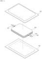
- FIG. 1 is a diagram of a pouch-type secondary battery before being sealed by a sealing device
- FIG. 2 is a diagram of a pouch-type secondary battery sealed by a sealing device.
- an upper pouch 100 and a lower pouch 100' are each disposed in the upper and lower parts of an electrode assembly 300 electrically connected to an electrode tab 420 and an electrode lead 400 wrapped around with a lead film 410 by being extended from the electrode tab 420, and the electrode lead 400 is protruded to the outside in a state in which the electrode assembly 300 is accommodated between the upper pouch 100 and the lower pouch 100' to seal the edges of the upper pouch 100 and the lower pouch 100'.
- the upper pouch 100 and the lower pouch 100' include sealed areas 101, 101' in which their respective edges are heat-sealed by the sealing device 500, and unsealed areas 102, 102' that are unsealed.
- the pouch-type secondary battery 10 has a structure in which the electrode assembly 300 and the electrolyte are embedded in a pouch-shaped laminate sheet capable of accommodating the electrode assembly 300, and it performs heat-sealing in which heat and pressure are applied to the upper pouch 100 and the lower pouch 100' including the laminate sheets so that the electrode assembly 300 is not exposed to the outside and there is no leakage of electrolyte.
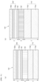
- FIG. 3 shows an electrode lead and upper and lower pouches before being pressed and heated with a sealing device
- FIG. 4 shows upper and lower pouches surrounding an electrode lead after being pressed and heated with a sealing device.
- the sealing device 500 which is an exemplary embodiment, includes an upper sealing block 510 and a lower sealing block 520 to pressurize and heat a laminated structure in which an upper pouch 100 and a lower pouch 100' are disposed in the upper and lower parts of an electrode lead 400 from both upper and lower directions.
- the upper sealing block 510 has a two-level upper sealing groove 513 including a first upper step 511 forming the bottom surface and a second upper step 512 formed between the first upper step 511 and the surface.
- the bottom surface means the lowest surface of the upper sealing groove 513, and the surface means the highest surface.
- the upper sealing groove 513 forms two steps with respect to the upper sealing block 510.
- the lower sealing block 520 also has a lower sealing groove 523 similar thereto.
- the lower sealing groove 523 forms a two-level step including a first lower step 521 constituting the bottom surface and a second lower step 522 formed between the first lower step 521 and the surface.
- the lower sealing block 520 rises to support the lower pouch 100' and the electrode lead 400, and then the upper sealing block 510 descends to apply heat and pressure. Since more heat is applied by the lower sealing block 520 first contacting the lower pouch 100', the sealing process of the pouch-type secondary battery 10 essentially applies more heat to the lower pouch 100'. That is, the lower pouch 100 ' to which more heat is supplied is more elongated than the upper pouch 100. For this reason, the sealed area 101' of the lower pouch is asymmetrically thinner than the sealed area 101 of the upper pouch.
- the present disclosure intentionally sets the thickness of the lower pouch 100' thicker than the thickness of the upper pouch 100 before the sealing treatment to alleviate or correct this essential asymmetry. Meanwhile, the thickness of the upper and lower pouches 100, 100' before the sealing process can be interpreted as equivalent to the thickness of the upper and lower pouches 100, 100' in the unsealed area after the sealing process, respectively.
- the first upper step 511 of the upper sealing block 510 corresponds to the upper part of the electrode lead 400
- the second upper step 512 corresponds to the upper part of the lead film 410
- the first lower step 521 of the lower sealing block 520 corresponds to the lower part of the electrode lead 400
- the second lower step 522 corresponds to the lower part of the lead film 410.
- the thickness of the lower pouch 100' is relatively thinner than the upper pouch 100 after sealing, so the lower pouch 100' is more vulnerable to pressure, and in order to solve the conventional problem of the sealed area of the lower pouch opening when the pouch 100' breaks due to the internal pressure of the gas generated in the pouch-type battery case, the thickness of the lower pouch 100' is made thicker than the thickness of the upper pouch 100 before sealing, so it is possible to form a uniform thickness by almost eliminating the deviation between the average thicknesses of the sealed area 101 of the upper pouch and the sealed area 101' of the lower pouch after sealing.
- the average thickness of the sealed area 101 of the upper pouch and the average thickness of the sealed area 101' of the lower pouch may satisfy Equation 1 below, and the average thickness of the unsealed area 102 of the upper pouch and the average thickness of the unsealed area 102' of the lower pouch may satisfy Equation 2 below. 0.95 ⁇ D 1 TOP / D 1 BOTTOM ⁇ 1.05
- D 1 TOP represents the average thickness of the sealed area of the upper pouch
- D 1 BOTTOM represents the average thickness of the sealed area of the lower pouch. 0.65 ⁇ D 2 TOP / D 2 BOTTOM ⁇ 0.95
- D 2 TOP represents the average thickness of the unsealed area 102 of the top pouch
- D 2 BOTTOM represents the average thickness of the unsealed area 102' of the bottom pouch.
- the sealed areas 101 and 101' of the upper and lower pouches refer to areas heated and pressurized by the sealing device 500.
- the average thickness D 1 TOP of the sealed area 101 of the upper pouch and the average thickness D 1 BOTTOM of the sealed area 101' of the lower pouch are the average thickness of the area heated and pressed by the sealing device 500, and its margin of error is about 5% or less.
- the unsealed areas 102, 102' of the upper and lower pouches refers to areas that are not heated and pressurized by the sealing device 500
- the average thickness D 2 TOP of the unsealed area 102 of the upper pouch and the average thickness D 2 BOTTOM of the unsealed area 102' of the lower pouch is the average thickness of the area not heated and pressurized by the sealing device 500, and is also the average thickness of the first upper and lower pouches before sealing.
- the average thickness D 1 BOTTOM of the sealed area 101' of the lower pouch and the average thickness D 1 TOP of the sealed area 101 of the upper pouch after the sealing process are not formed at an equivalent level (margin of error of average thickness is 5% or less), so it is difficult to achieve the intended purpose.
- the sealing process is performed using the upper and lower pouches 100, 100' having a thickness within the range described in the above Equation 2, it is possible to form thicknesses with an equivalent level in which there is little deviation between the average thicknesses of the upper and lower pouches 100, 100' in the sealed area after the sealing process.
- ranges of "D 1 TOP / D 1 BOTTOM” in 1 above and “D 2 TOP / D 2 BOTTOM” in 2 above are not limited to the ranges described above, and may be appropriately selected in consideration of the materials of the upper and lower pouches 100, 100', the heating temperature and the heating time of the sealing device 500, the thickness of the electrode assembly 300, and the like.
- the average thickness D 2 TOP of the unsealed area 102 of the upper pouch may be in the range of 130 to 165 ⁇ m
- the average thickness D 2 BOTTOM of the unsealed area 102' of the lower pouch may be in the range of 175 to 200 ⁇ m. This may also be appropriately selected in consideration of the material of the upper and lower pouches 100, 100', the heating temperature and the heating time of the sealing device 500, the thickness of the electrode assembly 300, and the like.
- the first upper step of the upper sealing block 510 is configured to have a smaller height A than the height A' of the first upper step of the lower sealing block 520
- the second upper step of the upper sealing block 510 is also configured to have a smaller height B than the height B' of the second upper step of the lower sealing block 520.
- the first and second lower steps 522 of the lower sealing block 520 are made deeper than the first and second upper steps 512 of the upper sealing block 510.
- the present disclosure provides a pouch-type secondary battery in which the upper pouch and the lower pouch in the sealed area have the same level of thickness after a sealing process is performed using a lower pouch having a thicker thickness than the upper pouch.
- FIG. 5 is a partially enlarged view of the "X-X” cross section of FIG. 2
- FIG. 6(a) and (b) are partially enlarged views of "Y" and "Z” of FIG. 5 , respectively.
- the upper pouch 100 and the lower pouch 100' may have a three-layer structure each including metal thin film layers 120, 120', first resin layers 110, 110' formed on the inside of the metal thin film layers 120, 120' facing the electrode assembly 300 or the electrode lead 400, and second resin layers 130, 130' formed on the outside of the metal thin film layers 120, 120'.
- the first resin layers 110, 110' include a polypropylene (PP) resin
- the second resin layers 130, 130' include a polyethylene terephthalate (PET) resin.
- first resin layers 110, 110' may further include acid- modified polypropylene (PPa), and PPa may refer to a material having a structure in which maleic acid is grafted to polypropylene (PP).
- PPa acid- modified polypropylene
- the second resin layer may further include a nylon (oriented nylon).
- the first resin layers 110, 110' are resin layers in contact with the electrode lead 400 coated with a lead film 410, and the melting point of the first resin layers 110, 110' is lower than that of the second resin layers 130, 130' in order to firmly fuse the upper and lower pouches 100, 100' to the electrode lead 400 or between the upper pouch 100 and the lower pouch 100'.
- the polypropylene (PP) resin has a melting point lower than that of the polyethylene terephthalate (PET) resin by about 100° C .
- the deviation between the average thicknesses D, E of the metal thin film layer 120 of the unsealed area of the upper pouch and the average thicknesses D, E of the second resin layer 130 and the average thicknesses D, E' of the metal thin film layer 120' and the second resin layer 130' is less than 5%, and the average thickness C of the first resin layer 110 of the unsealed area of the upper pouch is smaller than the average thickness C' of the first resin layer 110' of the unsealed area of the lower pouch (refer to FIG. 6 ).
- the average thicknesses of the sealed area 101 of the upper pouch and the sealed area 101' of the lower pouch area mainly influenced by the thicknesses C, C' of the first resin layer (that is, because the greatest change in the thickness of the first resin layer occurs before and after molding by the sealing device), so the overall thickness of the pouch can be easily controlled by controlling only the thicknesses C, C' of the first resin layer.
- the average thickness C of the first resin layer C in the unsealed area of the upper pouch and the average thickness C' of the first resin layer 110' in the unsealed area 102' of the lower pouch may satisfy Equation 3 below. 0.55 ⁇ D 3 TOP / D 3 BOTTOM ⁇ 0.85
- D 3 TOP represents the average thickness of the first resin layer in the unsealed area of the upper pouch
- D 3 BOTTOM represents the average thickness of the first resin layer in the unsealed area of the lower pouch
- the average thickness of the sealed area 101 of the upper pouch and the sealed area 101' of the lower pouch is mainly influenced by the thicknesses C, C' of the first resin layers
- the range of "D 3 TOP /D 3 BOTTOM " of the above Equation 3 is less than 0.55
- the average thickness of the first resin layer 110' of the unsealed area of the lower pouch is excessively thicker than the average thickness of the first resin layer 110 in the unsealed area of the upper pouch, which may cause an imbalance in internal pressure generated inside the battery case, and after the sealing process, the sealed area 101 of the upper pouch may not withstand the internal pressure.
- the average thickness D 1 BOTTOM of the sealed area 101' of the lower pouch and the average thickness D 1 TOP of the sealed area 101 of the upper pouch after the sealing process are not formed in an equivalent level of thickness (margin of error of average thickness is 5% or less), so it is difficult to achieve the intended purpose.
- the range of "D 3 TOP /D 3 BOTTOM " in the above Equation 3 is not limited to the described range, and may be appropriately selected in consideration of the components of the first resin layers 110, 110', the heating temperature and the heating time of the sealing device 500, the thickness of the electrode assembly 300, and the like.
- the average thickness D 3 TOP of the first resin layer 110 of the unsealed area 102 of the upper pouch of the present disclosure may be in the range of 70 to 85 ⁇ m
- the average thickness D 3 BOTTOM of the first resin layer 110' of the unsealed area 102' of the lower pouch may be in the range of 100 to 125 ⁇ m.
- This also may be appropriately selected in consideration of the components of the first resin layer 110, 110', the heating temperature and the heating time of the sealing device 500, the thickness of the electrode assembly 300, and the like.
- FIG. 6(a) is an enlarged view of "Y” in FIG. 5
- FIG. 6(b) is an enlarged view of "Z” in FIG. 5
- the first resin layers 110, 110' of the upper pouch and the lower pouch may include PP layers 110a, 110a' and PPa layers 110b, 110b'
- the second resin layer may include PET layers 130b, 130b', adhesive layers 140, 140', and nylon layers 130a, 130a'.
- the PP layers 110a, 110a' of the first resin layers 110, 110' formed on the outer side facing the sealing device 500 they may be stacked in the order of: the PPa layers 110b, 110b', the metal thin film layers 120, 120', the nylon layers 130a, 130a', and the PET layers 130b, 130b'.
- Adhesive layers 140, 140' can be formed between the metal thin film layers 120, 120' and the nylon layers 130a, 130a', and the adhesive layers 140, 140' may also be formed between the nylon layers 130a, 130a' and the PET layers 130b, 130b'.
- the thickness of the unsealed area 102 of the upper pouch is smaller than the thickness of the unsealed area 102' of the lower pouch.
- the thickness E of the second resin layer 130 of the upper pouch and the thickness D of the metal thin film layer 120 are equal to the thickness E' of the second resin layer 130' and the thickness D' of the metal thin film layer, but the thickness C' of the first resin layer 110 of the lower pouch is thicker than the thickness C of the first resin layer 110 of the upper pouch. This is because, as described above, the average thickness of the sealed areas 101, 101' of the upper and lower pouches is mainly influenced by the thicknesses C, C' of the first resin layers 110, 110', respectively.
- the thickness of the unsealed area 102 of the upper pouch may be 153 ⁇ m, and the thickness of the unsealed area 102' of the lower pouch may be 183 ⁇ m.
- the thickness C of the first resin layer of the unsealed area 102 of the upper pouch may be 80 ⁇ m
- the thickness D of the metal thin film layer may be 40 ⁇ m
- the thickness of the second resin layer including the adhesive layer E may be 33 ⁇ m.
- the thickness C' of the first resin layer of the unsealed area 102' of the lower pouch may be 110 ⁇ m
- the thicknesses of the metal thin film layer and the second resin layer may have the same thickness as the thicknesses D and E of the metal thin film layer and the second resin layer of the unsealed area 102 of the upper pouch. This is just one example, and may be appropriately changed according to the purpose.
- the present disclosure provides a pouch-type secondary battery in which the upper pouch and the lower pouch in the sealed area have the same level of thickness after a sealing process.
- the third embodiment basically relates to another exemplary embodiment for resolving thermal imbalance more effectively while maintaining the first shape.
- FIG. 7(a) and (b) are partially enlarged views of upper and lower pouches according to another exemplary embodiment of the present disclosure, respectively.
- the elongation rate of the first resin layer 110 of the upper pouch and the first resin layer 110' of the lower pouch are different, and specifically, the elongation rate of the first resin layer 110 of the upper pouch is lower than that of the first resin layer 110 of the upper pouch. Because the elongation rate of the first resin layer 110' of the lower pouch is smaller than the elongation rate of the first resin layer 110 of the upper porch, even when heat and pressure are applied by the sealing device 500, it is possible to reduce the amount of change in thickness of the lower pouch 100'.
- the first resin layer 110 may be a silylated first resin layer 150.
- the silylated first resin layer 150 may include a silane compound capable of forming a silane cross-linked polypropylene resin through silylation with polypropylene (PP).
- PP polypropylene
- the vinyl group of the silane compound reacts with the radical portion of the polypropylene resin to graft the polypropylene (PP) resin.
- a silane compound is included in the first resin layer 110', a cross-linked structure is formed through chemical bonding with the polypropylene (PP) of the first resin layer 110', thereby increasing the melt strength of the polypropylene (PP), improving the viscoelasticity at high temperature, and increasing the mechanical strength at the same time, which makes it possible to lower the elongation rate.
- PP polypropylene
- silane compound examples include one or more selected from the group consisting of vinylsilane, vinylmethoxysilane, vinyldimethoxysilane, vinyltrimethoxysilane, vinylethoxysilane, vinyldiethoxysilane, vinyltriethoxysilane, vinylpropoxysilane, vinyldipropoxysilane, and vinyltripropoxysilane. More preferably, it may be one or more among vinylsilane, vinylmethoxysilane, vinyldimethoxysilane, and vinyltrimethoxysilane.
- a crosslinking accelerator may be further included in order to partially promote a cross-link between polypropylene (PP) resins that have formed a silane cross-link.
- An organotin compound may be used as the crosslinking accelerator, and preferably an octyl tin-based compound or a butyl tin-based compound may be used.
- the present disclosure provides a pouch-type secondary battery in which the upper pouch and the lower pouch in the sealed area have the same thickness after a sealing process.
- the fourth embodiment basically relates to another exemplary embodiment for resolving thermal imbalance more effectively while maintaining the first shape.
- FIG. 8(a) and (b) are partially enlarged views of the upper and lower pouches, respectively, according to another exemplary embodiment of the present disclosure.
- the exemplary embodiment of FIG. 8 is characterized in that the thermal conductivity of the metal thin film layer 120' of the lower pouch is greater than the thermal conductivity of the metal thin film layer 120 of the upper pouch.
- Heat supplied from the lower sealing groove 523 of the sealing device 500 to the second resin layer 130' of the lower pouch is transmitted to the first resin layer 110' by passing through the metal thin film layer 120' of the lower pouch.
- the amount of heat transferred from the second resin layer 130' to the first resin layer 110' can be reduced by lowering the thermal conductivity of the metal thin film layer 120' of the lower pouch. Therefore, by lowering the amount of heat supplied from the sealing device 500 to the first resin layer 110' by lowering the thermal conductivity of the metal thin film layer 120' of the lower pouch, the retention rate of the first resin layer 110' can be increased.
- the second resin layer 130' of the lower pouch absorbs most of the heat supplied from the lower sealing groove 523 and rather reduces the thickness of the second resin layer 130', reducing the retention rate of the second resin layer 130', so it is preferable to select the metal thin film layer 120' having an appropriate thermal conductivity.
- the metal thin film layers 120, 120' may be composed of any one or more among alloys of iron (Fe), carbon (C), chromium (Cr), and manganese (Mn), alloys of iron (Fe), carbon (C), chromium (Cr), and nickel (Ni), aluminum (Al), and copper (Cu).
- the present disclosure does not limit the material, but preferably, it is preferable to use aluminum (Al) in terms of flexibility.
- the metal thin film layer 120 of the upper pouch may be composed of aluminum (Al)
- the metal thin film layer 120' of the lower pouch may be composed of an alloy including aluminum (Al) and iron (Fe).
- the metal thin film layer 120' of the lower pouch is made of an alloy containing aluminum (Al) and iron (Fe), thereby relatively reducing the thermal conductivity compared to the metal thin film layer 120 of the upper pouch.
- the metal thin film layer 120' of the lower pouch may be composed of aluminum (Al)
- the metal thin film layer 120 of the upper pouch may be composed of an alloy including aluminum (Al) and copper (Cu).
- the metal thin film layer 120 of the upper pouch is made of an alloy containing aluminum (Al) and copper (Cu), thereby relatively reducing the thermal conductivity compared to the metal thin film layer 120' of the lower pouch.
- the present disclosure provides a manufacturing method of a pouch-type secondary battery in which the upper pouch and the lower pouch in the sealed area have the same thickness after a sealing process.
- the manufacturing method of the pouch-type secondary battery 10 includes preparing an electrode assembly 300, an electrode lead 400 extending from an electrode tab 420 of the electrode assembly 300, an upper pouch 100 covering the upper surfaces of the electrode assembly 300 and the electrode tab 420, the electrode assembly 300, and a lower pouch 100' covering the lower surfaces of the electrode assembly 300 and the electrode tab 420.
- it may include positioning the electrode lead 400 and the electrode assembly 300 between the upper pouch 100 and the lower pouch 100' and sealing by pressurizing and heating the edges of the upper pouch 100 and the lower pouch 100' using a sealing device 500.
- the average thickness of the sealed area 101 of the upper pouch and the average thickness of the sealed area 101' of the lower pouch may be equal to each other, and the average thickness of the unsealed area 102 of the upper pouch may be smaller than the average thickness of the unsealed area 102' of the lower pouch.
- the average thickness of the sealed area 101 of the upper pouch and the average thickness of the sealed area 101' of the lower pouch may satisfy Equation 1 below, and the average thickness of the unsealed area 102 of the upper pouch and the average thickness of the unsealed area 102' of the lower pouch may satisfy Equation 2 below. 0.95 ⁇ D 1 TOP / D 1 BOTTOM ⁇ 1.05
- D 1 TOP represents the average thickness of the sealed area of the upper pouch
- D 1 BOTTOM represents the average thickness of the sealed area of the lower pouch. 0.65 ⁇ D 2 TOP / D 2 BOTTOM ⁇ 0.95
- D 2 TOP represents the average thickness of the unsealed area of the top pouch
- D 2 BOTTOM represents the average thickness of the unsealed area of the bottom pouch
- the upper pouch and the lower pouch in the preparing step each may include metal thin film layers 120, 120', second resin layers 130, 130' formed on the inside facing the electrode lead 400 or the electrode assembly 300 with respect to the metal thin film layers 120, 120', and first resin layers 110, 110' formed on the outer side with respect to the metal thin film layers 120, 120'.
- the deviation between the average thickness of the metal thin film layer 120 and the second resin layer 130 of the unsealed area 102 of the upper pouch and the average thickness of the metal thin film layer 120' and the second resin layer 130' of the unsealed area 102' of the lower pouch may be 5% or less, and the average thickness of the first resin layer 110 of the upper pouch may be smaller than the average thickness of the first resin layer 110' of the lower pouch.
- the average thickness of the first resin layer 110 in the unsealed area 102 of the upper pouch and the average thickness of the first resin layer 110' in the unsealed area 102' of the lower pouch may satisfy Equation 3 below. 0.55 ⁇ D 3 TOP / D 3 BOTTOM ⁇ 0.85
- D 3 TOP represents the average thickness of the first resin layer in the unsealed area of the upper pouch
- D 3 BOTTOM represents the average thickness of the first resin layer in the unsealed area of the lower pouch
- the sealed areas 101, 101' of the upper pouch and the lower pouch may have equal thicknesses. Accordingly, an imbalance, in which the sealing part opens due to an internal pressure concentrated only in the sealed area 101' of the lower pouch having a conventionally thin thickness, can be improved.
Landscapes
- Chemical & Material Sciences (AREA)
- Chemical Kinetics & Catalysis (AREA)
- Electrochemistry (AREA)
- General Chemical & Material Sciences (AREA)
- Engineering & Computer Science (AREA)
- Manufacturing & Machinery (AREA)
- Mechanical Engineering (AREA)
- Inorganic Chemistry (AREA)
- Sealing Battery Cases Or Jackets (AREA)
- Secondary Cells (AREA)
Applications Claiming Priority (2)
| Application Number | Priority Date | Filing Date | Title |
|---|---|---|---|
| KR1020220005802A KR102900633B1 (ko) | 2022-01-14 | 2022-01-14 | 파우치형 이차전지 및 이의 제조방법 |
| PCT/KR2023/000475 WO2023136594A1 (fr) | 2022-01-14 | 2023-01-11 | Batterie secondaire de type poche et son procédé de fabrication |
Publications (2)
| Publication Number | Publication Date |
|---|---|
| EP4283733A1 true EP4283733A1 (fr) | 2023-11-29 |
| EP4283733A4 EP4283733A4 (fr) | 2025-04-16 |
Family
ID=87279445
Family Applications (1)
| Application Number | Title | Priority Date | Filing Date |
|---|---|---|---|
| EP23740438.9A Pending EP4283733A4 (fr) | 2022-01-14 | 2023-01-11 | Batterie secondaire de type poche et son procédé de fabrication |
Country Status (6)
| Country | Link |
|---|---|
| US (1) | US20240145830A1 (fr) |
| EP (1) | EP4283733A4 (fr) |
| JP (1) | JP7662165B2 (fr) |
| KR (2) | KR102900633B1 (fr) |
| CN (1) | CN116918118A (fr) |
| WO (1) | WO2023136594A1 (fr) |
Families Citing this family (3)
| Publication number | Priority date | Publication date | Assignee | Title |
|---|---|---|---|---|
| WO2025080035A1 (fr) * | 2023-10-13 | 2025-04-17 | 주식회사 엘지에너지솔루션 | Ensemble électrode et batterie secondaire au lithium le comprenant |
| KR102833983B1 (ko) * | 2023-12-22 | 2025-07-14 | 율촌화학 주식회사 | 이차 전지용 파우치 외장재 및 이차 전지 |
| KR102914708B1 (ko) * | 2023-12-22 | 2026-01-19 | 율촌화학 주식회사 | 이차 전지용 파우치 외장재 및 이차 전지 |
Family Cites Families (19)
| Publication number | Priority date | Publication date | Assignee | Title |
|---|---|---|---|---|
| JP2007048669A (ja) * | 2005-08-11 | 2007-02-22 | Nissan Motor Co Ltd | 電池 |
| JP5793788B2 (ja) * | 2009-05-21 | 2015-10-14 | エルジー ケム. エルティーディ. | 耐水性パウチ型二次電池 |
| JP2013026173A (ja) * | 2011-07-26 | 2013-02-04 | Sanyo Electric Co Ltd | ラミネート外装電池 |
| KR101459179B1 (ko) * | 2011-12-08 | 2014-11-10 | 주식회사 엘지화학 | 파우치형 이차 전지 |
| KR20140062294A (ko) * | 2012-11-14 | 2014-05-23 | 주식회사 엘지화학 | 파우치형 폴리머 전지 및 그의 제조방법 |
| KR101578794B1 (ko) * | 2013-03-04 | 2015-12-22 | 주식회사 엘지화학 | 우수한 결합력의 전극리드-전극 탭 결합부를 포함하는 전지셀 |
| EP2899769B1 (fr) * | 2013-11-27 | 2019-01-30 | LG Chem, Ltd. | Pochette pour batterie rechargeable et batterie rechargeable comprenant cette pochette |
| KR102175038B1 (ko) * | 2014-03-24 | 2020-11-06 | 에스케이이노베이션 주식회사 | 방습성이 개선된 이차전지용 파우치 |
| KR101852662B1 (ko) * | 2015-01-22 | 2018-04-26 | 주식회사 엘지화학 | 이차전지용 파우치 외장재 및 이를 포함하는 파우치형 이차전지 |
| KR101852250B1 (ko) * | 2015-04-02 | 2018-04-26 | 주식회사 엘지화학 | 파우치형 이차전지의 실링 장치 |
| KR20160120089A (ko) * | 2015-04-07 | 2016-10-17 | 주식회사 엘지화학 | 이차 전지용 리드 부재 및 이를 포함하는 파우치형 이차 전지 |
| JP2016225186A (ja) * | 2015-06-01 | 2016-12-28 | オートモーティブエナジーサプライ株式会社 | リチウムイオン二次電池 |
| KR101925982B1 (ko) | 2015-11-11 | 2018-12-06 | 주식회사 엘지화학 | 파우치형 이차전지 및 그의 제조방법 |
| JP6786802B2 (ja) * | 2016-01-15 | 2020-11-18 | 大日本印刷株式会社 | 電池用包装材料 |
| KR102038308B1 (ko) * | 2016-01-29 | 2019-10-30 | 주식회사 엘지화학 | 서로 다른 열전도성의 케이스들을 포함하고 있는 전지셀 |
| KR102065128B1 (ko) * | 2016-03-29 | 2020-01-10 | 주식회사 엘지화학 | 파우치형 이차 전지 |
| JP7024540B2 (ja) * | 2018-03-22 | 2022-02-24 | Tdk株式会社 | 電気化学素子 |
| KR102835332B1 (ko) * | 2019-12-09 | 2025-07-17 | 주식회사 엘지에너지솔루션 | 보호필름을 이용한 파우치형 전지셀의 제조방법 및 이를 이용하여 제조된 파우치형 전지셀 |
| KR102405843B1 (ko) | 2020-07-07 | 2022-06-07 | 송원용 | 선반장치 |
-
2022
- 2022-01-14 KR KR1020220005802A patent/KR102900633B1/ko active Active
-
2023
- 2023-01-11 EP EP23740438.9A patent/EP4283733A4/fr active Pending
- 2023-01-11 CN CN202380010166.9A patent/CN116918118A/zh active Pending
- 2023-01-11 US US18/279,360 patent/US20240145830A1/en active Pending
- 2023-01-11 JP JP2023550668A patent/JP7662165B2/ja active Active
- 2023-01-11 WO PCT/KR2023/000475 patent/WO2023136594A1/fr not_active Ceased
-
2025
- 2025-12-09 KR KR1020250193806A patent/KR20260005125A/ko active Pending
Also Published As
| Publication number | Publication date |
|---|---|
| JP2024507547A (ja) | 2024-02-20 |
| KR102900633B1 (ko) | 2025-12-15 |
| KR20260005125A (ko) | 2026-01-09 |
| CN116918118A (zh) | 2023-10-20 |
| EP4283733A4 (fr) | 2025-04-16 |
| WO2023136594A1 (fr) | 2023-07-20 |
| JP7662165B2 (ja) | 2025-04-15 |
| KR20230109941A (ko) | 2023-07-21 |
| US20240145830A1 (en) | 2024-05-02 |
Similar Documents
| Publication | Publication Date | Title |
|---|---|---|
| US20240145830A1 (en) | Pouch-Type Secondary Battery and Manufacturing Method Therefor | |
| KR100708023B1 (ko) | 필름 외장 전기 디바이스 및 그 제조 방법 | |
| CN101904029B (zh) | 具有改进的安全性的袋型二次电池 | |
| EP2012376B1 (fr) | Batterie secondaire | |
| US20090263703A1 (en) | Cap assembly and secondary battery using the same | |
| KR102667401B1 (ko) | 파우치 성형 장치 및 방법 | |
| CN104488108B (zh) | 蓄电池单池和用于封闭蓄电池单池的方法 | |
| EP4094928B1 (fr) | Dispositif et procédé pour plier un côté | |
| CN116349064B (zh) | 软包型电池壳体、其成型设备及软包型二次电池 | |
| EP4037049A1 (fr) | Batterie secondaire et bloc d'étanchéité | |
| JP4235990B2 (ja) | 二次電池 | |
| CN115428239B (zh) | 电池单元和包括该电池单元的电池模块 | |
| EP4261016B1 (fr) | Batterie de type poche et dispositif de scellage pour batterie de type poche | |
| US20250149694A1 (en) | Battery Case, Battery Case Shaping Apparatus, and Secondary Battery Manufacturing Method | |
| EP4742388A1 (fr) | Procédé et moule pour sceller des batteries de type poche et batterie de type poche | |
| US20260135212A1 (en) | Method and mold for sealing pouch-type batteries and pouch-type battery | |
| KR100522683B1 (ko) | 리튬 2차전지 | |
| EP4712221A1 (fr) | Batterie et procédé de fabrication de la batterie | |
| KR102558420B1 (ko) | 이차전지 | |
| US20260066311A1 (en) | Secondary battery and manufacturing method thereof | |
| EP4539218A1 (fr) | Dispositif d'étanchéité de batterie secondaire | |
| KR20260034591A (ko) | 이차 전지 | |
| CN120435791A (zh) | 二次电池和用于制造该二次电池的密封装置 | |
| KR20260026909A (ko) | 파우치형 이차 전지, 이의 프레스 장치 및 이의 제조 방법 | |
| KR20250144087A (ko) | 이차 전지 |
Legal Events
| Date | Code | Title | Description |
|---|---|---|---|
| STAA | Information on the status of an ep patent application or granted ep patent |
Free format text: STATUS: THE INTERNATIONAL PUBLICATION HAS BEEN MADE |
|
| PUAI | Public reference made under article 153(3) epc to a published international application that has entered the european phase |
Free format text: ORIGINAL CODE: 0009012 |
|
| STAA | Information on the status of an ep patent application or granted ep patent |
Free format text: STATUS: REQUEST FOR EXAMINATION WAS MADE |
|
| 17P | Request for examination filed |
Effective date: 20230821 |
|
| AK | Designated contracting states |
Kind code of ref document: A1 Designated state(s): AL AT BE BG CH CY CZ DE DK EE ES FI FR GB GR HR HU IE IS IT LI LT LU LV MC ME MK MT NL NO PL PT RO RS SE SI SK SM TR |
|
| A4 | Supplementary search report drawn up and despatched |
Effective date: 20250317 |
|
| RIC1 | Information provided on ipc code assigned before grant |
Ipc: H01M 50/133 20210101ALI20250311BHEP Ipc: H01M 10/058 20100101ALI20250311BHEP Ipc: H01M 50/131 20210101ALI20250311BHEP Ipc: H01M 50/129 20210101ALI20250311BHEP Ipc: H01M 50/105 20210101ALI20250311BHEP Ipc: H01M 50/124 20210101ALI20250311BHEP Ipc: H01M 50/126 20210101ALI20250311BHEP Ipc: H01M 50/178 20210101ALI20250311BHEP Ipc: H01M 50/176 20210101ALI20250311BHEP Ipc: H01M 50/184 20210101ALI20250311BHEP Ipc: H01M 50/183 20210101ALI20250311BHEP Ipc: H01M 10/04 20060101AFI20250311BHEP |
|
| DAV | Request for validation of the european patent (deleted) | ||
| DAX | Request for extension of the european patent (deleted) |