EP4285471B1 - Endkappe für elektromotoren und motoreinheit mit einem mit der endkappe verbundenen elektromotor - Google Patents
Endkappe für elektromotoren und motoreinheit mit einem mit der endkappe verbundenen elektromotor Download PDFInfo
- Publication number
- EP4285471B1 EP4285471B1 EP22705470.7A EP22705470A EP4285471B1 EP 4285471 B1 EP4285471 B1 EP 4285471B1 EP 22705470 A EP22705470 A EP 22705470A EP 4285471 B1 EP4285471 B1 EP 4285471B1
- Authority
- EP
- European Patent Office
- Prior art keywords
- end cap
- housing
- electric motor
- motor
- coupling seat
- Prior art date
- Legal status (The legal status is an assumption and is not a legal conclusion. Google has not performed a legal analysis and makes no representation as to the accuracy of the status listed.)
- Active
Links
Images


Classifications
-
- H—ELECTRICITY
- H02—GENERATION; CONVERSION OR DISTRIBUTION OF ELECTRIC POWER
- H02K—DYNAMO-ELECTRIC MACHINES
- H02K5/00—Casings; Enclosures; Supports
- H02K5/04—Casings or enclosures characterised by the shape, form or construction thereof
- H02K5/16—Means for supporting bearings, e.g. insulating supports or means for fitting bearings in the bearing-shields
- H02K5/173—Means for supporting bearings, e.g. insulating supports or means for fitting bearings in the bearing-shields using bearings with rolling contact, e.g. ball bearings
- H02K5/1732—Means for supporting bearings, e.g. insulating supports or means for fitting bearings in the bearing-shields using bearings with rolling contact, e.g. ball bearings radially supporting the rotary shaft at both ends of the rotor
-
- H—ELECTRICITY
- H02—GENERATION; CONVERSION OR DISTRIBUTION OF ELECTRIC POWER
- H02K—DYNAMO-ELECTRIC MACHINES
- H02K5/00—Casings; Enclosures; Supports
- H02K5/04—Casings or enclosures characterised by the shape, form or construction thereof
- H02K5/15—Mounting arrangements for bearing-shields or end plates
-
- H—ELECTRICITY
- H02—GENERATION; CONVERSION OR DISTRIBUTION OF ELECTRIC POWER
- H02K—DYNAMO-ELECTRIC MACHINES
- H02K11/00—Structural association of dynamo-electric machines with electric components or with devices for shielding, monitoring or protection
- H02K11/30—Structural association with control circuits or drive circuits
- H02K11/33—Drive circuits, e.g. power electronics
-
- H—ELECTRICITY
- H02—GENERATION; CONVERSION OR DISTRIBUTION OF ELECTRIC POWER
- H02K—DYNAMO-ELECTRIC MACHINES
- H02K5/00—Casings; Enclosures; Supports
- H02K5/04—Casings or enclosures characterised by the shape, form or construction thereof
- H02K5/06—Cast metal casings
-
- H—ELECTRICITY
- H02—GENERATION; CONVERSION OR DISTRIBUTION OF ELECTRIC POWER
- H02K—DYNAMO-ELECTRIC MACHINES
- H02K5/00—Casings; Enclosures; Supports
- H02K5/04—Casings or enclosures characterised by the shape, form or construction thereof
- H02K5/18—Casings or enclosures characterised by the shape, form or construction thereof with ribs or fins for improving heat transfer
-
- H—ELECTRICITY
- H02—GENERATION; CONVERSION OR DISTRIBUTION OF ELECTRIC POWER
- H02K—DYNAMO-ELECTRIC MACHINES
- H02K5/00—Casings; Enclosures; Supports
- H02K5/04—Casings or enclosures characterised by the shape, form or construction thereof
- H02K5/22—Auxiliary parts of casings not covered by groups H02K5/06-H02K5/20, e.g. shaped to form connection boxes or terminal boxes
- H02K5/225—Terminal boxes or connection arrangements
-
- H—ELECTRICITY
- H02—GENERATION; CONVERSION OR DISTRIBUTION OF ELECTRIC POWER
- H02K—DYNAMO-ELECTRIC MACHINES
- H02K11/00—Structural association of dynamo-electric machines with electric components or with devices for shielding, monitoring or protection
- H02K11/20—Structural association of dynamo-electric machines with electric components or with devices for shielding, monitoring or protection for measuring, monitoring, testing, protecting or switching
- H02K11/21—Devices for sensing speed or position, or actuated thereby
- H02K11/215—Magnetic effect devices, e.g. Hall-effect or magneto-resistive elements
-
- H—ELECTRICITY
- H02—GENERATION; CONVERSION OR DISTRIBUTION OF ELECTRIC POWER
- H02K—DYNAMO-ELECTRIC MACHINES
- H02K5/00—Casings; Enclosures; Supports
- H02K5/04—Casings or enclosures characterised by the shape, form or construction thereof
Definitions
- the invention relates to an end cap for electric motors, preferably for brushless motors.
- the present invention relates to a motor unit comprising an electric motor associated with the above-mentioned end cap.
- motor units of the electric type comprise an electric motor, in particular a brushless motor, which in turn generally includes a containment case for a stator body and a rotor with a motor shaft.
- the motor unit generally comprises an output cap with an output for the motor shaft and an end cap, opposite the output cap, on which an electronic control unit for the electric motor is possibly housed.
- the electronic control unit is positioned outside the end cap, inside a protective shroud which extends externally to the cap itself in the axial direction.
- Document US 2018/115224 discloses an end cap for electric motors, configured to be associated with one of said electric motors at the axial end opposite the output end of the motor shaft, wherein said end cap comprises, made as a single body, a coupling seat for associating said electric motor in the axial direction and a housing for an electronic control unit; said housing extending from a perimeter portion of said coupling seat, in an axial direction and in the coupling direction of said coupling seat with said electric motor, so that when the electric motor is coupled to the coupling seat, the housing faces the electric motor; the outer surface of the housing having in the central part a concave shape in the radial direction facing downwards towards the containment case of the electric motor so as to follow the course of said containment case of said electric motor.
- the present invention is intended to overcome the aforesaid drawbacks of the prior art.
- a first aim of the invention is the realisation of an end cap for electric motors which enables the axial and radial dimensions of the motor unit in which it is used to be reduced.
- a further aim of the invention is the realisation of an end cap for electric motors which makes it easier to assemble the motor units in which such a cap is used.
- a further aim of the invention is the realisation of an end cap for electric motors which allows easy and quick access by an operator to its internal components.
- the aim of the invention is to realise an end cap that makes it possible to reduce the number of components of a motor unit in which it is used.
- the motor unit comprising an electric motor and the above-mentioned end cap according to claim 17 is also part of the invention.
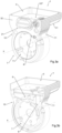
- the end cap of the invention for electric motors preferably for brushless motors, is shown in isolation in figs. 1 to 9 , wherein it is indicated overall by 1, and is shown assembled in a motor unit 100 in figs. 10 to 17 .
- the end cap 1 of the invention is configured to be associated with an electric motor 101 at the axial end 102 thereof, opposite the output end 103 of the motor shaft 104.
- the end cap 1 comprises, made as a single body, a coupling seat 2 for association with said electric motor 101 in the axial direction and a housing 3 for an electronic control unit 105.
- such end cap 1 is made as a single body by means of a die-casting process. More specifically, such end cap 1 is made of die-cast aluminium.
- the central part of the coupling seat 2 has a housing for a slewing bearing 22.
- said housing 3 extends, starting from a perimeter portion 21 of the coupling seat 2, in an axial direction and in the coupling direction of the coupling seat 2 with the electric motor 101, as clearly visible in figs. 4 , 6 and 14 .
- this housing 3 when the electric motor 101 is coupled to the aforementioned coupling seat 2, faces the electric motor 101 as shown in fig. 10 .
- said housing 3 extends, from said perimeter portion 21 of the coupling seat 2, in an axial direction and exclusively in the coupling direction of the coupling seat 2.
- the end cap 1 has the same dimensions both in its portion axially opposite the coupling seat 2, and in correspondence with the radially extending wall 32 delimiting the housing 3, on the opposite side of said coupling seat 2.
- the motor unit 100 advantageously, makes it possible to keep the motor unit 100 essentially composed of the aforementioned end cap 1 and of the electric motor 101 extremely compact.
- the motor unit 100 comprising the aforementioned end cap 1, substantially has the same dimensions as the electric motor 101.
- this makes it possible to use the same end cap 1 also in the event that it is required to equip the motor unit 100 with further functional components, such as, for example, a cooling fan 112, as shown in figs. 16a and 16b , or a brake 113, as shown in fig. 17 , which can be associated on the same end cap 1 on the opposite side of the aforesaid coupling seat 2.
- a cooling fan 112 as shown in figs. 16a and 16b
- a brake 113 as shown in fig. 17
- the end cap 1 provides for not defining within it an area in which to place such external functional components, but the end cap 1 itself is configured to associate the aforementioned external components to the rear of said coupling seat 2, in particular, as will be seen shortly, at the edge of a containment recess 7.
- this housing 3 is accessible in a radial direction, on the opposite side of the aforesaid coupling seat 2.
- such a set of features of the end cap 1 allows easy access, by an operator, to its internal components, in particular it allows easy installation of the electronic control unit 105 and, if necessary, easy intervention thereon without having to disassociate the same end cap 1 from the electric motor 101.
- this electrical/electronic connection assembly 107 is preferably, but not necessarily, oriented in the axial direction.
- the end cap 1 further comprises a first closing element 4, which can be reversibly coupled to the housing 3 and in proximity to the same to prevent access thereto. Conversely, once this first closing element 4 has been disassociated from the single body of the end cap 1, as indicated above, it is possible to access the housing 3 in a radial direction.
- the contact surfaces of the first closing element 4 and the housing 3 for their coupling are flat surfaces, so that they can be easily closed with a gasket and thus achieve increased IP protection.
- such first closing element 4 may be made of another material, for example plastic, provided that it is capable of appropriately dissipating the thermal energy generated by the electronic control unit 105 arranged in said housing 3.
- such fastening means are threaded holes made in the bottom of said housing 3, used to fasten the electronic control unit 105 by means of screws.
- the bottom of the housing 3 is defined as substantially continuous and planar in such a way as, advantageously, to allow direct and extensive contact with the bottom of the electronic control unit 105 located within the housing 3 itself. This further optimises the dissipation of the heat generated by the electronic control unit 105 itself.
- fastening means are made on the inner wall of the first closing element 4, which is adapted to face the housing 3 when the same closing element 4 is placed in the closure of the latter.
- the fact that the electronic control unit 105 can be fastened to said inner wall of the first closing element 4 facilitates the dissipation of the thermal energy generated by the electronic control unit 105 itself.
- said outer surface 31 of the housing 3 is shaped in such a way as to be distanced from the containment case 106 of the electric motor 101, thus not coming into contact with said containment case when the same electric motor 101 is coupled to the coupling seat 2 of the end cap 1.
- said spacing between said outer surface 31 and the containment case 106 is comprised between 1 and 30 mm.
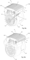
- this outer surface 31 of the housing 3 adapted to face the electric motor 101, spaced apart from the same and thus not in contact with such electric motor when the latter is associated with the seat, has a plurality of cooling fins 5. This feature allows the structure of the housing 3 to be used as a heat sink for the heat generated by the electronic control unit 105 and by the electric motor 101, as well as allowing the internal arrangement of the electronic control unit itself.
- such outer surface 31 has in the central part 31a said concavity facing downwards, i.e. towards the containment case 106 of the electric motor 101, so as to follow the course of such containment case 106 and optimise heat dissipation.
- said outer surface 31 exhibits, in correspondence with both lateral parts 31b and 31c , a concavity facing upwards; therefore, such lateral parts 31b and 31c of the outer surface 31 exhibit a downwards convexity.
- such particular shaping of the outer surface 31 advantageously allows, as mentioned above, to optimise, in correspondence with its central part 31a, a heat exchange effect of the heat generated by the electric motor 101 and by the electronic control unit 105, and on the other hand, the concavities facing upwards, made in correspondence with the lateral parts 31b and 31c of such outer surface 31, allow the size of the same outer surface 31 to be increased and also the circulation of air flows around the latter to be promoted, further maximising heat dispersion.
- the housing 3 in correspondence with the section extending from the perimeter portion 21 of the coupling seat 2 presents on both sides two curvilinear areas 10 and 11 recessed with respect to the width presented by the same housing 3 in the section extending in the axial direction and in the coupling direction of the coupling seat 2.
- said two recessed curvilinear areas 10 and 11 in case a cooling fan 112 is provided in correspondence with the rear part of the end cap 1, advantageously allow the flow of cooling air towards said outer surface 31 to be promoted, further optimising the thermal dissipation of the heat produced both by the electric motor 101 and by the electronic control unit 105.
- the end cap 1 In order to electrically/electronically connect the electronic control unit 105 to the electric motor 101, in order to control the latter, the end cap 1 provides a first internal communication channel 6 between the housing 3 and the area in which the aforementioned coupling seat 2 is defined, as can be seen in fig. 3b and in fig. 7 .
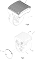
- the end cap 1 further has a containment recess 7 defined to curve inwards in the axial direction on the opposite side of the coupling seat 2.
- such containment recess 7 is defined by a cavity 71 with a circular profile which extends in an axial direction towards the coupling seat 2.
- the presence of the aforementioned containment recess 7 allows the insertion, within the footprint of the end cap 1, of an encoder 110 coaxially to the axis X of the motor shaft 104 of the electric motor 101.
- an encoder 110 is a Hall sensor 111.
- the fact that the encoder 110 is arranged within the aforementioned recessed containment recess 7 allows an operator to access it easily, without the need to disassemble the end cap 1 from the electric motor 101.
- a second closing element 9 of substantially discoidal shape is provided, which can be reversibly coupled to the containment recess 7 and in proximity to the same in order to prevent access thereto.
- the motor unit 100 is also part of the invention, a first preferred embodiment of which is shown in figs. 10 to 14 .
- Said motor unit 100 comprises an electric motor 101, in particular a brushless motor, provided with a containment case 106 for a stator body and a rotor, not shown in the figures, with a motor shaft 104 and an electronic control unit 105 configured to control said electric motor 101.
- the motor unit 100 also comprises an end cap 1 of the invention, the features of which have been described above.
- Such end cap 1 is associated with the coupling seat 2 thereof with the electric motor 101, at the axial end 102 of the latter, opposite the output end 103 of the motor shaft 104.
- the electronic control unit 105 as shown in fig. 11 , is inserted in the housing 3 of the same end cap 1.
- the motor unit 100 of the invention provides a first electrical/electronic connection 108 between the electronic control unit 105 and the electric motor 101, via the first internal communication channel 6.
- an encoder 110 is also located within the containment recess 7.
- a second preferred embodiment of the motor unit 100 of the invention is depicted in figs. 16a and 16b .
- This second embodiment of the motor unit 100 includes all the features described for the first embodiment represented by fig. 10 to fig. 14 , except that, instead of including the second closing element 9 arranged to close the containment recess 7, it provides for the installation of a cooling fan 112, behind said containment recess 7, as represented in fig. 16a , and of a protective shroud 113 arranged externally to such cooling fan 112, as shown in fig. 16b .
- cooling fan 112 is directly fitted onto the motor shaft 104 and turns solidly constrained to the electric motor 101.
- the distinctive shaping of the end cap 1 of the invention in particular the presence of the aforementioned two recessed curvilinear areas 10 and 11, and, moreover, the proximity of the housing 3 with respect to the cooling fan 112, allow to direct part of the cooling air flow generated by the same fan 112 towards the outer surface 31, as well as towards the lateral surfaces of the same housing 3, as represented by the arrows of fig. 16a .
- cooling air flow is advantageously able to increase and speed up the heat exchange between the internal high-temperature part of the housing 3, due to the heat generated by the electronic control unit 105, and the cooling air flow itself.
- a brake 113 electrically connected to the same electronic control unit 105 could be associated with the end cap 1, to the rear of the aforesaid containment recess 7, by means of a connector or a terminal board at said wall 32. This means that, even when such a brake 113 is installed, the IP degree of protection provided by the end cap 1 of the invention is maintained unchanged.
- a further advantageous aspect of the end cap 1 of the invention consists of the fact that it has a great degree of versatility, in the sense that its size and shape remain unchanged regardless of whether a cooling fan 112 and/or a brake 113 is associated with it at the rear, or whether said containment recess 7 is closed with the second closing element 9 of substantially discoidal shape.
- the aforesaid end cap 1 is, on the one hand, configured in order to be able to associate an external functional element therewith, such as a cooling fan 112 or a brake 113, and on the other hand it is defined in such a way as to have minimal dimensions in case it is not associated with any external functional element, as is clearly observed in fig. 15 .
- the end cap 1 of the invention and the motor unit 100 achieve all the above-mentioned purposes.
- a further aim achieved by the invention is the realisation of an end cap for electric motors which allows easy access by an operator to its internal components.
- Another aim reached by the invention is the realisation of an end cap for electric motors which makes it easier to assemble the motor units in which such a cap is used.
Landscapes
- Engineering & Computer Science (AREA)
- Power Engineering (AREA)
- Microelectronics & Electronic Packaging (AREA)
- Physics & Mathematics (AREA)
- Thermal Sciences (AREA)
- Motor Or Generator Frames (AREA)
- Power-Operated Mechanisms For Wings (AREA)
Claims (18)
- Endkappe (1) für Elektromotoren (101), vorzugsweise für bürstenlose Motoren, die so konfiguriert ist, dass sie mit einem der besagten Elektromotoren (101) am axialen Ende (102) gegenüber dem Ausgangsende (103) der Motorwelle (104) verbunden wird, wobei die besagte Endkappe (1) als Einzelkörper ausgeführt Folgendes umfasst:- einen Kupplungssitz (2) zum Verbinden des besagten Elektromotors (101) in der Axialrichtung;- ein Gehäuse (3) für eine elektronische Steuereinheit (105), wobei sich das besagte Gehäuse (3) von einem Umfangsabschnitt (21) des besagten Kupplungssitzes (2) in einer Axialrichtung und in der Kupplungsrichtung des besagten Kupplungssitzes (2) mit dem besagten Elektromotor (101) erstreckt, sodass, wenn der besagte Elektromotor (101) mit dem besagten Kupplungssitz (2) gekoppelt ist, das besagte Gehäuse (3) zum besagten Elektromotor (101) zeigt, wobei die Außenfläche (31) des besagten Gehäuses (3) im mittleren Teil (31a) eine konkave Form in der Radialrichtung aufweist, die nach unten zum Einschlussraum (106) des besagten Elektromotors (101) zeigt, sodass sie dem Verlauf des Einschlussraums (106) des besagten Elektromotors (101) folgt;dadurch gekennzeichnet, dass die besagte Außenfläche (31) des besagten Gehäuses (3) so konfiguriert ist, dass sie, wenn die besagte Endkappe (1) mit dem besagten Elektromotor (101) verbunden ist, vom besagten Einschlussraum (106) des besagten Elektromotors (101) beabstandet ist, wobei der besagte Abstand vorzugsweise zwischen 1 und 30 mm liegt, wobei die besagte Außenfläche (31) in Übereinstimmung mit den beiden Seitenteilen (31b, 31c) davon eine nach oben zeigende Konkavität aufweist, um die Größe der besagten Außenfläche (31) zu vergrößern und die Zirkulation von Luftströmen um die besagte Außenfläche (31) herum zu fördern; wobei das besagte Gehäuse (3) in Übereinstimmung mit der Sektion, die sich vom besagten Umfangsabschnitt (21) des besagten Kupplungssitzes (2) erstreckt, auf jeder Seite einen krummlinigen Bereich (10, 11) aufweist, der in Bezug auf die Breite, die das besagte Gehäuse (3) in Übereinstimmung mit der sich in der Axialrichtung erstreckenden Sektion aufweist, ausgespart ist.
- Endkappe (1) nach Patentanspruch 1, dadurch gekennzeichnet, dass die besagte Außenfläche (31) des besagten Gehäuses (3), die dazu geeignet ist, zum besagten Elektromotor (101) zu zeigen, wenn er mit dem besagten Kupplungssitz (2) verbunden ist, eine Vielzahl von Kühlrippen (5) aufweist.
- Endkappe (1) nach jeglichem der vorhergehenden Patentansprüche, dadurch gekennzeichnet, dass sie als Einzelkörper aus Aluminiumdruckguss ausgeführt ist.
- Endkappe (1) nach jeglichem der vorhergehenden Patentansprüche, dadurch gekennzeichnet, dass die besagte im Inneren des besagten Gehäuses (3) angeordnete elektronische Steuereinheit (105) zumindest in der Radialrichtung zugänglich ist.
- Endkappe (1) nach jeglichem der vorhergehenden Patentansprüche 1 bis 3, dadurch gekennzeichnet, dass die besagte im Inneren des besagten Gehäuses (3) angeordnete elektronische Steuereinheit (105) zumindest in der Axialrichtung zugänglich ist.
- Endkappe (1) nach jeglichem der vorhergehenden Patentansprüche, dadurch gekennzeichnet, dass sich das besagte Gehäuse (3) von einem Umfangsabschnitt (21) des besagten Kupplungssitzes (2) in einer Axialrichtung und ausschließlich in der Kupplungsrichtung des besagten Kupplungssitzes (2) mit dem besagten Elektromotor (101) erstreckt.
- Endkappe (1) nach jeglichem der vorhergehenden Patentansprüche, dadurch gekennzeichnet, dass ein erstes Verschlusselement (4) vorgesehen ist, das reversibel mit dem besagten Gehäuse (3) und in der Nähe davon gekoppelt werden kann, um den Zugang dazu zu verhindern.
- Endkappe (1) nach Patentanspruch 7, dadurch gekennzeichnet, dass das besagte erste Verschlusselement (4) an seiner Außenfläche (41) eine Vielzahl von Kühlrippen (42) aufweist.
- Endkappe (1) nach jeglichem der Patentansprüche 7 oder 8, dadurch gekennzeichnet, dass die Kontaktflächen des besagten ersten Verschlusselements (4) und des besagten Gehäuses (3) für die Kupplung davon ebene Flächen sind, um ein relatives Verschließen mit einer Dichtung zu erleichtern.
- Endkappe (1) nach jeglichem der vorhergehenden Patentansprüche, dadurch gekennzeichnet, dass sie eine elektrische/elektronische Verbindungsanordnung (107) umfasst, die zumindest einen elektrischen/ elektronischen Steckverbinder bzw. einen Anschlussblock umfasst und auf der sich radial erstreckenden Wand (32), die das besagte Gehäuse (3) begrenzt, auf der gegenüberliegenden Seite des besagten Kupplungssitzes (2) definiert ist, wobei die besagte elektrische/elektronische Verbindungsanordnung (107) vorzugsweise in einer Axialrichtung ausgerichtet ist.
- Endkappe (1) nach jeglichem der vorangehenden Patentansprüche, dadurch gekennzeichnet, dass der Boden des besagten Gehäuses (3) im Wesentlichen durchgängig und flach definiert ist, sodass ein direkter und umfassender Kontakt zwischen dem besagten Boden und der besagten im Inneren des besagten Gehäuses (3) angeordneten elektronischen Steuereinheit (105) möglich ist.
- Endkappe (1) nach jeglichem der vorhergehenden Patentansprüche, dadurch gekennzeichnet, dass sie einen ersten inneren Kommunikationskanal (6) zwischen dem besagten Gehäuse (3) und dem Bereich, in dem der besagte Kupplungssitz (2) definiert ist, aufweist.
- Endkappe (1) nach jeglichem der vorhergehenden Patentansprüche, dadurch gekennzeichnet, dass sie eine Einschlussaussparung (7) aufweist, die so definiert ist, dass sie sich in der Axialrichtung auf der gegenüberliegenden Seite des Elektromotors (101) des besagten Kupplungssitzes (2) nach innen krümmt.
- Endkappe (1) nach Patentanspruch 13, dadurch gekennzeichnet, dass die besagte Einschlussaussparung (7) durch einen Hohlraum (71) mit einem kreisförmigen Profil definiert ist, der sich in einer Axialrichtung zum besagten Kupplungssitz (2) erstreckt.
- Endkappe (1) nach jeglichem der Patentansprüche 13 oder 14, dadurch gekennzeichnet, dass sie einen zweiten inneren Kommunikationskanal (8) zwischen dem besagten Gehäuse (3) und der besagten Einschlussaussparung (7) aufweist.
- Endkappe (1) nach jeglichem der Patentansprüche 13 bis 15, dadurch gekennzeichnet, dass sie ein zweites Verschlusselement (9) von im Wesentlichen scheibenartiger Form umfasst, das reversibel mit der besagten Einschlussaussparung (7) und in der Nähe davon gekoppelt werden kann, um den Zugang dazu zu verhindern.
- Motoreinheit (100), umfassend:- einen Elektromotor (101), insbesondere einen bürstenlosen Motor, der mit einem Einschlussraum (106) für einen Statorkörper und einen Rotor mit einer Motorwelle (104) vorgesehen ist;- eine elektronische Steuereinheit (105), die so konfiguriert ist, dass sie den besagten Elektromotor (101) steuert;dadurch gekennzeichnet, dass sie eine Endkappe (1) nach jeglichem der vorhergehenden Patentansprüche umfasst, wobei die besagte Endkappe (1) mit dem besagten Elektromotor (101) am axialen Ende (102) gegenüber dem Ausgangsende (103) der Motorwelle (104) verbunden ist, wobei die besagte elektronische Steuereinheit (105) in das besagte Gehäuse (3) der besagten Endkappe (1) eingesetzt ist.
- Motoreinheit (100) nach Patentanspruch 17 in Kombination mit jeglichem der Patentansprüche 13-16, dadurch gekennzeichnet, dass sie ein reversibles Einbauen eines Kühlgebläses (112) oder einer Bremse (113) an der Rückseite der besagten Einschlussaussparung (7) vorsieht.
Applications Claiming Priority (2)
| Application Number | Priority Date | Filing Date | Title |
|---|---|---|---|
| IT102021000001841A IT202100001841A1 (it) | 2021-01-29 | 2021-01-29 | Calotta di chiusura per motori elettrici, e gruppo motore comprendente un motore elettrico associato alla suddetta calotta di chiusura |
| PCT/IB2022/050749 WO2022162599A1 (en) | 2021-01-29 | 2022-01-28 | End cap for electric motors, and motor unit comprising an electric motor associated with said end cap |
Publications (3)
| Publication Number | Publication Date |
|---|---|
| EP4285471A1 EP4285471A1 (de) | 2023-12-06 |
| EP4285471C0 EP4285471C0 (de) | 2025-03-12 |
| EP4285471B1 true EP4285471B1 (de) | 2025-03-12 |
Family
ID=75850443
Family Applications (1)
| Application Number | Title | Priority Date | Filing Date |
|---|---|---|---|
| EP22705470.7A Active EP4285471B1 (de) | 2021-01-29 | 2022-01-28 | Endkappe für elektromotoren und motoreinheit mit einem mit der endkappe verbundenen elektromotor |
Country Status (5)
| Country | Link |
|---|---|
| US (1) | US12401251B2 (de) |
| EP (1) | EP4285471B1 (de) |
| CN (1) | CN116762263A (de) |
| IT (1) | IT202100001841A1 (de) |
| WO (1) | WO2022162599A1 (de) |
Family Cites Families (19)
| Publication number | Priority date | Publication date | Assignee | Title |
|---|---|---|---|---|
| US6205644B1 (en) * | 1997-12-04 | 2001-03-27 | Emerson Electric Co. | Method of assembling an electric motor |
| EP1146625A3 (de) * | 2000-04-10 | 2004-04-28 | Kabushiki Kaisha MORIC | Rotierende elektrische Maschine |
| JP3593102B2 (ja) * | 2002-01-08 | 2004-11-24 | 三菱電機株式会社 | 電動パワーステアリング装置 |
| US20050023912A1 (en) * | 2003-07-28 | 2005-02-03 | A.O. Smith Corporation | Electric motor for hydromassage bathtubs |
| DK1735893T3 (da) * | 2004-04-01 | 2008-11-24 | Sew Eurodrive Gmbh & Co | Elektromotor og serie af elektromotorer |
| DE102005032968A1 (de) * | 2005-07-14 | 2007-02-08 | Siemens Ag | Umrichtermotor |
| DE102008028622B4 (de) * | 2008-06-18 | 2025-05-15 | Sew-Eurodrive Gmbh & Co Kg | Elektromotor |
| US8912698B2 (en) * | 2011-10-03 | 2014-12-16 | Elco Motor Yachts, LLC | Motor assembly with integrated cooling means and enclosed compartment for electronic circuitry |
| EP2607707B2 (de) * | 2011-12-23 | 2022-11-23 | Grundfos Holding A/S | Elektromotor |
| CN203251543U (zh) | 2013-05-15 | 2013-10-23 | 安波电机(宁德)有限公司 | 一种具有散热设计的电机控制器外壳及集成调速电机 |
| JP6447048B2 (ja) * | 2014-11-20 | 2019-01-09 | 日本電産株式会社 | モータ |
| CN104467298B (zh) | 2014-12-11 | 2017-02-22 | 范兆军 | 一体结构的电机 |
| JP2016192832A (ja) * | 2015-03-30 | 2016-11-10 | 日本電産株式会社 | モータ |
| WO2017026128A1 (ja) * | 2015-08-11 | 2017-02-16 | 三菱電機株式会社 | モータ装置 |
| CN205141934U (zh) * | 2015-10-20 | 2016-04-06 | 卧龙电气集团股份有限公司 | 新型一体式变频电机 |
| CN105840527B (zh) * | 2016-05-17 | 2018-06-15 | 中山宝扇电器有限公司 | 方便维护的吊扇 |
| CN109114007B (zh) | 2018-08-23 | 2025-01-10 | 浙江东欣节能科技有限公司 | 电动水泵 |
| DE102020006366A1 (de) * | 2020-10-16 | 2022-04-21 | KSB SE & Co. KGaA | Kreiselpumpe mit einem Antrieb |
| EP4480071A1 (de) * | 2022-02-15 | 2024-12-25 | SEW-EURODRIVE GmbH & Co. KG | Elektromotor mit einem anschlusskasten |
-
2021
- 2021-01-29 IT IT102021000001841A patent/IT202100001841A1/it unknown
-
2022
- 2022-01-28 US US18/256,718 patent/US12401251B2/en active Active
- 2022-01-28 WO PCT/IB2022/050749 patent/WO2022162599A1/en not_active Ceased
- 2022-01-28 EP EP22705470.7A patent/EP4285471B1/de active Active
- 2022-01-28 CN CN202280012039.8A patent/CN116762263A/zh active Pending
Also Published As
| Publication number | Publication date |
|---|---|
| US20240048017A1 (en) | 2024-02-08 |
| IT202100001841A1 (it) | 2022-07-29 |
| EP4285471C0 (de) | 2025-03-12 |
| WO2022162599A1 (en) | 2022-08-04 |
| US12401251B2 (en) | 2025-08-26 |
| CN116762263A (zh) | 2023-09-15 |
| EP4285471A1 (de) | 2023-12-06 |
Similar Documents
| Publication | Publication Date | Title |
|---|---|---|
| EP2973957B1 (de) | Luftgekühlte elektrische maschine und verfahren zur montage davon | |
| US8016574B2 (en) | Cooling fan for a motor vehicle | |
| US6439862B2 (en) | Fan with improved electric motor and mounting | |
| JP7285266B2 (ja) | 電気モータ並びに電気モータを製造するための方法 | |
| CN111010856B (zh) | Pcb电路板散热结构及具有其的烹饪器具 | |
| US20160006325A1 (en) | Electric machine, in particular an engine | |
| US9667115B2 (en) | Electronic housing for an electric motor with protection against accidental contact | |
| US6364004B1 (en) | Cooling fan, in particular a radiator fan for motor vehicles | |
| CN204706978U (zh) | 电机壳体及电机 | |
| JPH09252563A (ja) | 制御装置一体型モータ | |
| EP4285471B1 (de) | Endkappe für elektromotoren und motoreinheit mit einem mit der endkappe verbundenen elektromotor | |
| EP3539202B1 (de) | Elektrische maschine mit flüssigkeitskühlung | |
| CN110319011B (zh) | 电动压缩机 | |
| JP4755177B2 (ja) | 自動車用回転電機 | |
| KR100193936B1 (ko) | 블레이드 부싱형 전동기 | |
| KR20160135042A (ko) | 차량용 공조장치 및 이의 블로어 유닛 제조방법 | |
| CN213757929U (zh) | 料理机基座和料理机 | |
| JP4768737B2 (ja) | 空冷式の電子回路を有する電動機 | |
| CA3108557A1 (en) | Operator control unit for a steering wheel, and steering wheel having the same | |
| US12155290B2 (en) | Electronically commutated rotating electrical machine with a gap in a housing for cooling air flow | |
| US20240055950A1 (en) | Rotating electrical machine | |
| NO20211451A1 (en) | Electric motor with integrated cooling | |
| JP2001132697A (ja) | モータファン | |
| CN121461670A (zh) | 一种导风结构及一体式电机 |
Legal Events
| Date | Code | Title | Description |
|---|---|---|---|
| STAA | Information on the status of an ep patent application or granted ep patent |
Free format text: STATUS: UNKNOWN |
|
| STAA | Information on the status of an ep patent application or granted ep patent |
Free format text: STATUS: THE INTERNATIONAL PUBLICATION HAS BEEN MADE |
|
| PUAI | Public reference made under article 153(3) epc to a published international application that has entered the european phase |
Free format text: ORIGINAL CODE: 0009012 |
|
| STAA | Information on the status of an ep patent application or granted ep patent |
Free format text: STATUS: REQUEST FOR EXAMINATION WAS MADE |
|
| 17P | Request for examination filed |
Effective date: 20230806 |
|
| AK | Designated contracting states |
Kind code of ref document: A1 Designated state(s): AL AT BE BG CH CY CZ DE DK EE ES FI FR GB GR HR HU IE IS IT LI LT LU LV MC MK MT NL NO PL PT RO RS SE SI SK SM TR |
|
| DAV | Request for validation of the european patent (deleted) | ||
| DAX | Request for extension of the european patent (deleted) | ||
| GRAP | Despatch of communication of intention to grant a patent |
Free format text: ORIGINAL CODE: EPIDOSNIGR1 |
|
| STAA | Information on the status of an ep patent application or granted ep patent |
Free format text: STATUS: GRANT OF PATENT IS INTENDED |
|
| INTG | Intention to grant announced |
Effective date: 20241004 |
|
| GRAS | Grant fee paid |
Free format text: ORIGINAL CODE: EPIDOSNIGR3 |
|
| GRAA | (expected) grant |
Free format text: ORIGINAL CODE: 0009210 |
|
| STAA | Information on the status of an ep patent application or granted ep patent |
Free format text: STATUS: THE PATENT HAS BEEN GRANTED |
|
| AK | Designated contracting states |
Kind code of ref document: B1 Designated state(s): AL AT BE BG CH CY CZ DE DK EE ES FI FR GB GR HR HU IE IS IT LI LT LU LV MC MK MT NL NO PL PT RO RS SE SI SK SM TR |
|
| REG | Reference to a national code |
Ref country code: GB Ref legal event code: FG4D |
|
| REG | Reference to a national code |
Ref country code: CH Ref legal event code: EP |
|
| REG | Reference to a national code |
Ref country code: DE Ref legal event code: R096 Ref document number: 602022011711 Country of ref document: DE |
|
| REG | Reference to a national code |
Ref country code: IE Ref legal event code: FG4D |
|
| U01 | Request for unitary effect filed |
Effective date: 20250326 |
|
| U07 | Unitary effect registered |
Designated state(s): AT BE BG DE DK EE FI FR IT LT LU LV MT NL PT RO SE SI Effective date: 20250401 |
|
| PG25 | Lapsed in a contracting state [announced via postgrant information from national office to epo] |
Ref country code: RS Free format text: LAPSE BECAUSE OF FAILURE TO SUBMIT A TRANSLATION OF THE DESCRIPTION OR TO PAY THE FEE WITHIN THE PRESCRIBED TIME-LIMIT Effective date: 20250612 |
|
| PG25 | Lapsed in a contracting state [announced via postgrant information from national office to epo] |
Ref country code: ES Free format text: LAPSE BECAUSE OF FAILURE TO SUBMIT A TRANSLATION OF THE DESCRIPTION OR TO PAY THE FEE WITHIN THE PRESCRIBED TIME-LIMIT Effective date: 20250312 |
|
| PG25 | Lapsed in a contracting state [announced via postgrant information from national office to epo] |
Ref country code: NO Free format text: LAPSE BECAUSE OF FAILURE TO SUBMIT A TRANSLATION OF THE DESCRIPTION OR TO PAY THE FEE WITHIN THE PRESCRIBED TIME-LIMIT Effective date: 20250612 |
|
| PG25 | Lapsed in a contracting state [announced via postgrant information from national office to epo] |
Ref country code: HR Free format text: LAPSE BECAUSE OF FAILURE TO SUBMIT A TRANSLATION OF THE DESCRIPTION OR TO PAY THE FEE WITHIN THE PRESCRIBED TIME-LIMIT Effective date: 20250312 |
|
| PG25 | Lapsed in a contracting state [announced via postgrant information from national office to epo] |
Ref country code: GR Free format text: LAPSE BECAUSE OF FAILURE TO SUBMIT A TRANSLATION OF THE DESCRIPTION OR TO PAY THE FEE WITHIN THE PRESCRIBED TIME-LIMIT Effective date: 20250613 |
|
| PG25 | Lapsed in a contracting state [announced via postgrant information from national office to epo] |
Ref country code: SM Free format text: LAPSE BECAUSE OF FAILURE TO SUBMIT A TRANSLATION OF THE DESCRIPTION OR TO PAY THE FEE WITHIN THE PRESCRIBED TIME-LIMIT Effective date: 20250312 |
|
| PG25 | Lapsed in a contracting state [announced via postgrant information from national office to epo] |
Ref country code: PL Free format text: LAPSE BECAUSE OF FAILURE TO SUBMIT A TRANSLATION OF THE DESCRIPTION OR TO PAY THE FEE WITHIN THE PRESCRIBED TIME-LIMIT Effective date: 20250312 |
|
| PG25 | Lapsed in a contracting state [announced via postgrant information from national office to epo] |
Ref country code: CZ Free format text: LAPSE BECAUSE OF FAILURE TO SUBMIT A TRANSLATION OF THE DESCRIPTION OR TO PAY THE FEE WITHIN THE PRESCRIBED TIME-LIMIT Effective date: 20250312 |
|
| PG25 | Lapsed in a contracting state [announced via postgrant information from national office to epo] |
Ref country code: SK Free format text: LAPSE BECAUSE OF FAILURE TO SUBMIT A TRANSLATION OF THE DESCRIPTION OR TO PAY THE FEE WITHIN THE PRESCRIBED TIME-LIMIT Effective date: 20250312 |
|
| PG25 | Lapsed in a contracting state [announced via postgrant information from national office to epo] |
Ref country code: IS Free format text: LAPSE BECAUSE OF FAILURE TO SUBMIT A TRANSLATION OF THE DESCRIPTION OR TO PAY THE FEE WITHIN THE PRESCRIBED TIME-LIMIT Effective date: 20250712 |
|
| PLBE | No opposition filed within time limit |
Free format text: ORIGINAL CODE: 0009261 |
|
| STAA | Information on the status of an ep patent application or granted ep patent |
Free format text: STATUS: NO OPPOSITION FILED WITHIN TIME LIMIT |
|
| REG | Reference to a national code |
Ref country code: CH Ref legal event code: L10 Free format text: ST27 STATUS EVENT CODE: U-0-0-L10-L00 (AS PROVIDED BY THE NATIONAL OFFICE) Effective date: 20260121 |
|
| 26N | No opposition filed |
Effective date: 20251215 |
|
| U20 | Renewal fee for the european patent with unitary effect paid |
Year of fee payment: 5 Effective date: 20260129 |