EP4285871A2 - Fremdkraftbetätigbare prothese - Google Patents
Fremdkraftbetätigbare prothese Download PDFInfo
- Publication number
- EP4285871A2 EP4285871A2 EP23205304.1A EP23205304A EP4285871A2 EP 4285871 A2 EP4285871 A2 EP 4285871A2 EP 23205304 A EP23205304 A EP 23205304A EP 4285871 A2 EP4285871 A2 EP 4285871A2
- Authority
- EP
- European Patent Office
- Prior art keywords
- prosthesis
- control device
- operated
- microcontroller
- gripping process
- Prior art date
- Legal status (The legal status is an assumption and is not a legal conclusion. Google has not performed a legal analysis and makes no representation as to the accuracy of the status listed.)
- Granted
Links
Images


Classifications
-
- A—HUMAN NECESSITIES
- A61—MEDICAL OR VETERINARY SCIENCE; HYGIENE
- A61F—FILTERS IMPLANTABLE INTO BLOOD VESSELS; PROSTHESES; DEVICES PROVIDING PATENCY TO, OR PREVENTING COLLAPSING OF, TUBULAR STRUCTURES OF THE BODY, e.g. STENTS; ORTHOPAEDIC, NURSING OR CONTRACEPTIVE DEVICES; FOMENTATION; TREATMENT OR PROTECTION OF EYES OR EARS; BANDAGES, DRESSINGS OR ABSORBENT PADS; FIRST-AID KITS
- A61F2/00—Filters implantable into blood vessels; Prostheses, i.e. artificial substitutes or replacements for parts of the body; Appliances for connecting them with the body; Devices providing patency to, or preventing collapsing of, tubular structures of the body, e.g. stents
- A61F2/50—Prostheses not implantable in the body
- A61F2/68—Operating or control means
- A61F2/70—Operating or control means electrical
-
- A—HUMAN NECESSITIES
- A61—MEDICAL OR VETERINARY SCIENCE; HYGIENE
- A61F—FILTERS IMPLANTABLE INTO BLOOD VESSELS; PROSTHESES; DEVICES PROVIDING PATENCY TO, OR PREVENTING COLLAPSING OF, TUBULAR STRUCTURES OF THE BODY, e.g. STENTS; ORTHOPAEDIC, NURSING OR CONTRACEPTIVE DEVICES; FOMENTATION; TREATMENT OR PROTECTION OF EYES OR EARS; BANDAGES, DRESSINGS OR ABSORBENT PADS; FIRST-AID KITS
- A61F2/00—Filters implantable into blood vessels; Prostheses, i.e. artificial substitutes or replacements for parts of the body; Appliances for connecting them with the body; Devices providing patency to, or preventing collapsing of, tubular structures of the body, e.g. stents
- A61F2/50—Prostheses not implantable in the body
- A61F2/54—Artificial arms or hands or parts thereof
- A61F2/58—Elbows; Wrists ; Other joints; Hands
- A61F2/583—Hands; Wrist joints
- A61F2/586—Fingers
-
- A—HUMAN NECESSITIES
- A61—MEDICAL OR VETERINARY SCIENCE; HYGIENE
- A61F—FILTERS IMPLANTABLE INTO BLOOD VESSELS; PROSTHESES; DEVICES PROVIDING PATENCY TO, OR PREVENTING COLLAPSING OF, TUBULAR STRUCTURES OF THE BODY, e.g. STENTS; ORTHOPAEDIC, NURSING OR CONTRACEPTIVE DEVICES; FOMENTATION; TREATMENT OR PROTECTION OF EYES OR EARS; BANDAGES, DRESSINGS OR ABSORBENT PADS; FIRST-AID KITS
- A61F2/00—Filters implantable into blood vessels; Prostheses, i.e. artificial substitutes or replacements for parts of the body; Appliances for connecting them with the body; Devices providing patency to, or preventing collapsing of, tubular structures of the body, e.g. stents
- A61F2/50—Prostheses not implantable in the body
- A61F2/68—Operating or control means
- A61F2/70—Operating or control means electrical
- A61F2/72—Bioelectric control, e.g. myoelectric
-
- A—HUMAN NECESSITIES
- A61—MEDICAL OR VETERINARY SCIENCE; HYGIENE
- A61F—FILTERS IMPLANTABLE INTO BLOOD VESSELS; PROSTHESES; DEVICES PROVIDING PATENCY TO, OR PREVENTING COLLAPSING OF, TUBULAR STRUCTURES OF THE BODY, e.g. STENTS; ORTHOPAEDIC, NURSING OR CONTRACEPTIVE DEVICES; FOMENTATION; TREATMENT OR PROTECTION OF EYES OR EARS; BANDAGES, DRESSINGS OR ABSORBENT PADS; FIRST-AID KITS
- A61F2/00—Filters implantable into blood vessels; Prostheses, i.e. artificial substitutes or replacements for parts of the body; Appliances for connecting them with the body; Devices providing patency to, or preventing collapsing of, tubular structures of the body, e.g. stents
- A61F2/50—Prostheses not implantable in the body
- A61F2/78—Means for protecting prostheses or for attaching them to the body, e.g. bandages, harnesses, straps, or stockings for the limb stump
- A61F2/80—Sockets, e.g. of suction type
-
- A—HUMAN NECESSITIES
- A61—MEDICAL OR VETERINARY SCIENCE; HYGIENE
- A61F—FILTERS IMPLANTABLE INTO BLOOD VESSELS; PROSTHESES; DEVICES PROVIDING PATENCY TO, OR PREVENTING COLLAPSING OF, TUBULAR STRUCTURES OF THE BODY, e.g. STENTS; ORTHOPAEDIC, NURSING OR CONTRACEPTIVE DEVICES; FOMENTATION; TREATMENT OR PROTECTION OF EYES OR EARS; BANDAGES, DRESSINGS OR ABSORBENT PADS; FIRST-AID KITS
- A61F2/00—Filters implantable into blood vessels; Prostheses, i.e. artificial substitutes or replacements for parts of the body; Appliances for connecting them with the body; Devices providing patency to, or preventing collapsing of, tubular structures of the body, e.g. stents
- A61F2/50—Prostheses not implantable in the body
- A61F2/68—Operating or control means
- A61F2002/6881—Operating or control means optical
-
- A—HUMAN NECESSITIES
- A61—MEDICAL OR VETERINARY SCIENCE; HYGIENE
- A61F—FILTERS IMPLANTABLE INTO BLOOD VESSELS; PROSTHESES; DEVICES PROVIDING PATENCY TO, OR PREVENTING COLLAPSING OF, TUBULAR STRUCTURES OF THE BODY, e.g. STENTS; ORTHOPAEDIC, NURSING OR CONTRACEPTIVE DEVICES; FOMENTATION; TREATMENT OR PROTECTION OF EYES OR EARS; BANDAGES, DRESSINGS OR ABSORBENT PADS; FIRST-AID KITS
- A61F2/00—Filters implantable into blood vessels; Prostheses, i.e. artificial substitutes or replacements for parts of the body; Appliances for connecting them with the body; Devices providing patency to, or preventing collapsing of, tubular structures of the body, e.g. stents
- A61F2/50—Prostheses not implantable in the body
- A61F2/68—Operating or control means
- A61F2002/689—Alarm means, e.g. acoustic
-
- A—HUMAN NECESSITIES
- A61—MEDICAL OR VETERINARY SCIENCE; HYGIENE
- A61F—FILTERS IMPLANTABLE INTO BLOOD VESSELS; PROSTHESES; DEVICES PROVIDING PATENCY TO, OR PREVENTING COLLAPSING OF, TUBULAR STRUCTURES OF THE BODY, e.g. STENTS; ORTHOPAEDIC, NURSING OR CONTRACEPTIVE DEVICES; FOMENTATION; TREATMENT OR PROTECTION OF EYES OR EARS; BANDAGES, DRESSINGS OR ABSORBENT PADS; FIRST-AID KITS
- A61F2/00—Filters implantable into blood vessels; Prostheses, i.e. artificial substitutes or replacements for parts of the body; Appliances for connecting them with the body; Devices providing patency to, or preventing collapsing of, tubular structures of the body, e.g. stents
- A61F2/50—Prostheses not implantable in the body
- A61F2/68—Operating or control means
- A61F2/70—Operating or control means electrical
- A61F2002/704—Operating or control means electrical computer-controlled, e.g. robotic control
-
- A—HUMAN NECESSITIES
- A61—MEDICAL OR VETERINARY SCIENCE; HYGIENE
- A61F—FILTERS IMPLANTABLE INTO BLOOD VESSELS; PROSTHESES; DEVICES PROVIDING PATENCY TO, OR PREVENTING COLLAPSING OF, TUBULAR STRUCTURES OF THE BODY, e.g. STENTS; ORTHOPAEDIC, NURSING OR CONTRACEPTIVE DEVICES; FOMENTATION; TREATMENT OR PROTECTION OF EYES OR EARS; BANDAGES, DRESSINGS OR ABSORBENT PADS; FIRST-AID KITS
- A61F2/00—Filters implantable into blood vessels; Prostheses, i.e. artificial substitutes or replacements for parts of the body; Appliances for connecting them with the body; Devices providing patency to, or preventing collapsing of, tubular structures of the body, e.g. stents
- A61F2/50—Prostheses not implantable in the body
- A61F2/68—Operating or control means
- A61F2/70—Operating or control means electrical
- A61F2002/705—Electromagnetic data transfer
-
- A—HUMAN NECESSITIES
- A61—MEDICAL OR VETERINARY SCIENCE; HYGIENE
- A61F—FILTERS IMPLANTABLE INTO BLOOD VESSELS; PROSTHESES; DEVICES PROVIDING PATENCY TO, OR PREVENTING COLLAPSING OF, TUBULAR STRUCTURES OF THE BODY, e.g. STENTS; ORTHOPAEDIC, NURSING OR CONTRACEPTIVE DEVICES; FOMENTATION; TREATMENT OR PROTECTION OF EYES OR EARS; BANDAGES, DRESSINGS OR ABSORBENT PADS; FIRST-AID KITS
- A61F2/00—Filters implantable into blood vessels; Prostheses, i.e. artificial substitutes or replacements for parts of the body; Appliances for connecting them with the body; Devices providing patency to, or preventing collapsing of, tubular structures of the body, e.g. stents
- A61F2/50—Prostheses not implantable in the body
- A61F2/76—Means for assembling, fitting or testing prostheses, e.g. for measuring or balancing, e.g. alignment means
- A61F2002/7615—Measuring means
- A61F2002/7635—Measuring means for measuring force, pressure or mechanical tension
-
- A—HUMAN NECESSITIES
- A61—MEDICAL OR VETERINARY SCIENCE; HYGIENE
- A61F—FILTERS IMPLANTABLE INTO BLOOD VESSELS; PROSTHESES; DEVICES PROVIDING PATENCY TO, OR PREVENTING COLLAPSING OF, TUBULAR STRUCTURES OF THE BODY, e.g. STENTS; ORTHOPAEDIC, NURSING OR CONTRACEPTIVE DEVICES; FOMENTATION; TREATMENT OR PROTECTION OF EYES OR EARS; BANDAGES, DRESSINGS OR ABSORBENT PADS; FIRST-AID KITS
- A61F2/00—Filters implantable into blood vessels; Prostheses, i.e. artificial substitutes or replacements for parts of the body; Appliances for connecting them with the body; Devices providing patency to, or preventing collapsing of, tubular structures of the body, e.g. stents
- A61F2/50—Prostheses not implantable in the body
- A61F2/76—Means for assembling, fitting or testing prostheses, e.g. for measuring or balancing, e.g. alignment means
- A61F2002/7615—Measuring means
- A61F2002/769—Displaying measured values
-
- B—PERFORMING OPERATIONS; TRANSPORTING
- B25—HAND TOOLS; PORTABLE POWER-DRIVEN TOOLS; MANIPULATORS
- B25J—MANIPULATORS; CHAMBERS PROVIDED WITH MANIPULATION DEVICES
- B25J13/00—Controls for manipulators
Definitions
- the present invention describes a prosthesis that can be actuated by external force, comprising a prosthesis shaft and an exoprosthesis with at least one prosthesis motor that can be actuated by means of a prosthesis control device and a joint, the prosthesis control device comprising a housing, a microcontroller arranged therein and display means, so that a gripping process is carried out by the prosthesis motor that can be controlled by the prosthesis control device can be replicated and parameters of the gripping process can be displayed by the display means, with the recording and evaluation of electromyography signals being dispensed with.
- prostheses are in demand, comprising a prosthetic shaft with an exoprosthesis in the form of a hand or foot prosthesis, which are operated by external power.
- a prosthesis control device is connected to the exoprosthesis, by means of which at least one prosthesis motor is controlled so that at least one joint on the exoprosthesis can be moved.
- the movement of at least one finger joint is simulated, making a gripping movement possible.
- EMG electromyography
- the at least one prosthesis motor of the exoprosthesis is controlled by means of surface electrodes on the skin in the area of the limb stump of a prosthesis wearer.
- the muscle signals that can be picked up along the prosthesis shaft are recorded by the prosthesis control device using sensors and converted into movements of the exoprosthesis.
- WO2013038187 describes a method for controlling an EMG prosthesis, which allows the prosthesis wearer to train prosthesis movements even if the prosthesis is not ready for use.
- the exoprosthesis can either be moved or movements can be simulated in a computer, with the prosthesis wearer being able to train real movements using the latter.
- the prosthesis wearer can start predefined programs, for example for different gripping processes, using the correct muscle signals via computer and thus execute them through the exoprosthesis.
- gripping programs can run with computer support. However, this is associated with correspondingly increased technical effort.
- a prosthesis wearer can only have the stored programs carried out by the prosthesis, controlled by their EMG signals, which is not very flexible.
- the sensors, actuators and electronics for controlling the prostheses described are cost-intensive and very complex.
- the present invention has the task of creating a simple and cost-effective prosthesis that can be operated by external power, which can be operated without extensive training and requires few components.
- This prosthesis enables reproducible, non-destructive and safe gripping controlled by external force Objects of different hardness can be achieved, without the evaluation of electromyography signals and grip force sensors.
- the prosthesis control device of the prosthesis can be manipulated from the outside by a prosthesis wearer before and during the gripping movement, the grip force and the grip duration being easily and reliably adjusted by the prosthesis wearer and also being adjustable in real time by the prosthesis wearer during the gripping movement .
- the set grip strength and grip duration are transmitted to the prosthesis wearer optically, tactilely and/or acoustically.
- an external force-controlled prosthesis 1 comprising a prosthesis shaft 2, a coupling 3, an exoprosthesis 4 and a prosthesis control device 5 is shown and explained using the example of a hand prosthesis.
- the prosthesis shaft 2 is placed over an extremity stump 0 in the form of a forearm stump 0, indicated by dashed lines, and is releasably fastened.
- the hand prosthesis 4 is connected to the prosthesis shaft 2 by means of the coupling 3.
- a prosthesis motor is not shown here, but is designed in such a way that it can be controlled by the prosthesis control device 5, thereby forming a gripping process.
- the prosthesis control device 5 has a housing 50.
- the housing 50 is attached to a bracelet 51, which is placed around the prosthesis shaft 2, so that the prosthesis control device 5 is in the form of a wristwatch ( Fig. 1a ) or a sports armband ( Fig. 1b ) can be trained.
- the prosthesis control device 5 is attached to the outer surface of the prosthesis shaft 2 and is therefore spaced from the skin of the prosthesis wearer. This is easily possible since no myoelectric signals are recorded by the prosthesis control device 5.
- the prosthesis control device 5 and the housing 50 have input means 52 and display means 53.
- the input means 52 can also consist of virtual input buttons arranged on a user interface 520.
- the user interface 520 of the prosthesis control device 5 is from an outer surface Exoprosthesis 4, the prosthesis shaft 2 or the coupling 3 are arranged to project away and are therefore easily accessible.
- All input means 52 can be operated mechanically by a prosthesis wearer manually, i.e. with a finger. The operation is preferably carried out with at least one finger of the intact hand, but could also be operated using an aid held in the intact hand.
- a screen is designed as a display means 53 with a display area, while the input means 52 are buttons next to the screen 53.
- the prosthesis control device 5 enables the current grip force and the grip duration to be displayed on the screen 53, so that a prosthesis wearer can easily read the parameters with which the next gripping movement will take place.
- the display means 53 can be used to visually track how the gripping movement will or is taking place.
- the prosthesis control device 5 on the prosthesis shaft 2, as in Figure 1b shown, has a housing 50 with a bracelet 51 in the form of a sports bracelet or fitness bracelet.
- the prosthesis wearer can enter parameters into the prosthesis control device 5 via buttons 52, which can also be designed as capacitive or resistive switches 52 or pressure elements.
- Selection keys 521 are provided as input means 52, with which a mode or a parameter to be set can be set.
- size selection buttons 522 are provided.
- the display means 53 used here can be LEDs. The number of illuminated LEDs or the color of the illuminated LEDs can visually display the set parameters, such as grip strength or grip duration.
- the prosthesis control device 5 is integrated into the exoprosthesis 4, so that a prosthesis wearer can set the parameters and read the values directly on the hand prosthesis 4.
- the housing 50 is correspondingly integrated into the exoprosthesis 4 or a part of the hand prosthesis 4 forms the housing 50 of the prosthesis control device 5.
- the display means 53 can also be designed as a touch-sensitive screen, as in Figure 3 shown.
- An operating software (firmware) or application (app) is preferably operated on the prosthesis control device 5, which controls and displays the display means 53 and the input means 52.
- a user interface 520 is provided on the touch-sensitive screen as an input means 52.
- the user interface 520 here includes input means 52 in the form of virtual selection buttons 521 and virtual size selection buttons 522 in the form of sliders.
- the prosthesis control device 5 preferably comprises a single-board computer, for example an iOS board or a Raspberry Pi
- the prosthesis control device 5 can, in addition to controlling the exoprosthesis, also be used to operate other apps, as is known from smartphones and smartwatches. This means that, in addition to controlling the power-operated prosthesis, a prosthesis wearer can run apps for music or video playback, gaming applications, messaging or even making phone calls. Natural is a multi-process operation important, with the prosthesis control always taking priority over the other functions.
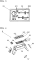
- a prosthesis control device 5 is shown in detail Figure 4 shown.
- a microcontroller 54 is stored in the housing 50 as the heart of the prosthesis control device 5, connected to a power supply 55.
- the power supply 55 is in the form of a rechargeable battery or one or more button batteries.
- a user interface 520 represents the input means 52 and LEDs 53' represent the display means 53. After parameters have been entered via the microcontroller 54, the currently set parameters are displayed optically by means of the LEDs 53'.
- a haptic motor driver 56 and a vibration motor 57 is also connected to the microcontroller 54 . Triggered by the microcontroller 54, the vibration motor 57 carries out vibrations that the prosthesis wearer can feel when the prosthesis control device 5 is arranged on the prosthesis shaft 2 or directly on the hand prosthesis 4.
- the haptic motor driver 56 in conjunction with the vibration motor 57 enables the prosthesis wearer to detect the grip contact of the hand prosthesis 4 through vibrations.
- the aim is to communicate the set parameters to the prosthesis wearer in a tactile manner, whereby a vibration can occur as soon as the grip movement has taken place with the set grip force or when an object has been gripped.
- the user interface 520 is designed here as a touch-sensitive PCB component (printed circuit board), with input taking place on touch-sensitive surfaces (touch pads). Selected parameters can be increased or decreased on the size selection buttons 522, shown as arrow-shaped areas. The parameters to be set can be varied using selection buttons 521. The one on the Values entered on the user interface 520 are forwarded to the microcontroller for further processing.
- an acceleration sensor 58 can be integrated into the prosthesis control device 5, which is also connected to the microcontroller 54.
- the acceleration sensor 58 can be used to register the movements and accelerations of the prosthesis control device 5 carried on the prosthesis shaft 2 and/or the exoprosthesis 4.
- the prosthesis control device 5 controls a gripping process using a microcontroller 54 on which operating software runs. Parameters are transmitted from the user interface 520 to the microcontroller 54 by input means 52, processed by the microcontroller 54 and displayed with the display means 53. Controlled by the microcontroller 54, the prosthesis motor movement is controlled as set. Even during the gripping process, the parameters can be readjusted in real time by the prosthesis wearer using input means 52.
- the power supply 55 is arranged in the prosthesis shaft 2, on the exoprosthesis 4, but could also be stored elsewhere on the body of the prosthesis wearer, for example in a trouser pocket.
- the prosthesis control device 5 can be arranged to at least partially cover the coupling 3 between the prosthesis shaft 2 and the exoprosthesis 4.
- What is sketched here is a connection from the prosthesis control device 5 to at least one finger joint of the hand prosthesis 4, which can be moved by the prosthesis control device 5.
- a prosthetic motor that can carry out the handle movement is indicated by dashed lines.
- the connection between prosthesis control device 5 and Hand prosthesis 4 or the at least one prosthesis motor can be done via a cable or wirelessly, for example via Bluetooth.
- the at least one prosthesis motor is controlled by the prosthesis control device 5 after entering the parameters, in particular the grip duration and the grip force.
- the at least one prosthesis motor is operated in a controlled manner by the microcontroller 54, and the parameters can also be changed in real time during the gripping process.
- the described prosthesis control device 5 is used to control and display the grip force or the grip duration of hand prostheses 4 operated by external power.
- the prosthesis wearer will manually set the grip force to be achieved and possibly a grip duration using the at least one prosthesis motor on the user interface 520.
- This setting is done with a finger of the intact hand, with the parameters being selected using selection buttons 521 and the size being defined using size selection buttons 522.
- the display means 53 indicate to the prosthesis wearer whether the desired settings have been made.
- the settings are passed from the input means 52 to the microcontroller 54, which subsequently controls the output means 53 and the movement of the hand prosthesis 4.
- the desired movement begins, which can be triggered, for example, by a defined position of the hand prosthesis 4 relative to the prosthesis shaft 2.
- the prosthesis wearer tracks the movement themselves, but also receives tactile feedback, for example about the beginning and end of the gripping movement using vibrations.
- the display means 53 also visually display the movement parameters and/or the course of the movement.
- the control of the at least one prosthesis motor based on the previously entered parameters is triggered and controlled by the microcontroller 54.
- the prosthesis wearer realizes that the gripping movement does not correspond to his wishes, he has the option of changing the parameters in real time via the user interface 520 while the hand prosthesis 4 is moving.
- the prosthesis wearer can also change the parameters manually.
- Adapted target values for example the grip force, are transmitted to the microcontroller 54.
- the microcontroller 54 controls the at least one prosthesis motor in a modified form. For example, an infinite period of time or a specific time voltage less than infinity can be considered as the grip duration. Due to the possibility of subsequently changing the parameters, the gripping movement can be ended at any time, with the prosthesis motor releasing the grip and opening the joint.
- the prosthesis wearer can freely specify the grip strength of the hand prosthesis 4 at any time via an externally portable module.
- start parameters can be specified by the prosthesis wearer before triggering. If it is recognized during the gripping movement that the grip force is too high because the objects to be gripped are softer than expected, the grip force can easily be readjusted. In this way, destruction of the grasped object can be ruled out.
- the tactile feedback using the vibration motor 57 can, for example, indicate when the object to be gripped is touched, gripped and released again. This means that the gripping process can be approximated to natural gripping.
- the parameters or feedback signals set on the prosthesis control device 5 during movement can also be transmitted in the form of acoustic feedback instead of optical and haptic signals. Accordingly, at least one loudspeaker and an acoustic module must be connected to the microcontroller 54, from which acoustic feedback signals can be transmitted to the prosthesis wearer.
- the software operated on the microcontroller 54 can, for example, acoustically report the set grip force or the successful completion of a gripping movement.
- the prosthesis control device 5 can be designed in several parts, with the input means 52 and the display means 53 not being arranged at the location of the housing 50, but rather being spatially separated from one another.
- the input means 52 can be designed in the form of the acoustic module connected to the microcontroller 54, with voice commands received by the acoustic module being used to input the desired grip force and/or grip duration on the microcontroller 54 of the prosthesis control device 5.
- the prosthesis wearer speaks directly into the prosthesis control device 5 or the acoustic module before carrying out a gripping process and reports the gripping force and/or gripping duration.
- the understood voice command is then displayed by the display means 53 and the handle can be carried out. This would result in a correspondingly voice-controlled prosthesis 1.
- the prosthesis control device 5 or the housing 50 is worn as part of the prosthesis 1 on the limb stump 0, the prosthesis control device can also be worn on the healthy or intact hand. The operation then takes place, for example, with a prosthetic finger if the input means 52 are designed in the form of manually operated buttons.
Landscapes
- Health & Medical Sciences (AREA)
- Transplantation (AREA)
- Orthopedic Medicine & Surgery (AREA)
- Heart & Thoracic Surgery (AREA)
- Engineering & Computer Science (AREA)
- Biomedical Technology (AREA)
- Oral & Maxillofacial Surgery (AREA)
- Vascular Medicine (AREA)
- Life Sciences & Earth Sciences (AREA)
- Animal Behavior & Ethology (AREA)
- General Health & Medical Sciences (AREA)
- Public Health (AREA)
- Veterinary Medicine (AREA)
- Cardiology (AREA)
- Prostheses (AREA)
Abstract
Description
- Die vorliegende Erfindung beschreibt eine fremdkraftbetätigbare Prothese, umfassend einen Prothesenschaft und eine Exoprothese mit mindestens einem mittels einer Prothesensteuerungsvorrichtung betätigbaren Prothesenmotor und einem Gelenk, wobei die Prothesensteuerungsvorrichtung ein Gehäuse, einen darin angeordneten Mikrokontroller und Anzeigemittel umfasst, sodass ein Greifprozess durch den von der Prothesensteuerungsvorrichtung steuerbaren Prothesenmotor nachbildbar ist und Parameter des Greifprozesses von den Anzeigemitteln darstellbar sind, wobei auf die Aufnahme und Auswertung von Elektromyografie-Signalen verzichtet wird.
- Heute sind bevorzugt Prothesen, umfassend einen Prothesenschaft mit einer Exoprothese in Form einer Hand- oder Fussprothese gefragt, welche fremdkraftbetätigt sind. Dabei wird eine Prothesensteuerungsvorrichtung mit der Exoprothese verbunden, mittels welcher mindestens ein Prothesenmotor angesteuert wird, sodass mindestens ein Gelenk an der Exoprothese bewegt werden kann. Im Falle einer Handprothese wird so die Bewegung mindestens eines Fingergelenkes nachgebildet, womit eine Greifbewegung möglich ist.
- Da passende elektronische Bauteile erhältlich und erschwinglich sind und möglichst realistische Nachbildungen natürlicher Hand- und Fussbewegungen anvisiert werden, werden Prothesen verbreitet mit Myoelektrik zur Verwendung von Elektromyografie (EMG) ausgerüstet. Durch EMG kann die elektrische Muskelaktivität ermittelt werden, woraus Steuersignale für die Prothesensteuerungsvorrichtung generiert werden können. Mittels Oberflächenelektroden auf der Haut im Bereich des Extremitätenstumpfes eines Prothesenträgers wird der mindestens eine Prothesenmotor der Exoprothese gesteuert. Die abgreifbaren Muskelsignale im Verlauf des Prothesenschafts werden mit der Prothesensteuerungsvorrichtung mittels Sensoren erfasst und in Bewegungen der Exoprothese umgesetzt.
- Neben einem gesteigerten technischen Aufwand für derartige myoelektrisch gesteuerte fremdkraftbetätigte Prothesen ist es notwendig, dass der Prothesenträger die Ansteuerung mittels myoelektrischer Signale trainiert. Die Nutzung einer Prothese mit EMG ist daher generell nur mit einem Lernprozess zur Ansteuerung der Prothese möglich, welcher oftmals langwierig ist. Die Algorithmen zur Erkennung der Benutzereingabe sind schwierig einstellbar und oft nicht reproduzierbar, sodass die Ansteuerung oft Probleme bereitet, wenn der Prothesenträger beispielsweise schwitzt und/oder sich die Oberflächenelektroden verschieben. Zusätzlich kann bei längerem Tragen solcher Prothesen das EMG-Signal, durch das Ermüden einzelner Muskelpartien, markant absinken.
- Um die bekannten Nachteile der Prothesen auf Basis von EMG-Signalen zu beseitigen, werden immer aufwändigere Lösungsvorschläge gemacht, was die Komplexität dieser Art von Prothesen weiter erhöht. Oftmals werden weitere Sensoren verwendet, um beispielsweise eine Greifbewegung noch genauer zu detektieren. Entsprechend wird die Prothesensteuerungsvorrichtung noch aufwändiger und die Prothesen werden noch teurer, was beispielsweise den Einsatz der Prothesen in der dritten Welt erschwert.
- Beispielsweise ist in der
WO2013038187 ein Verfahren zur Steuerung einer EMG-Prothese beschrieben, welches dem Prothesenträger erlaubt Prothesenbewegungen zu trainieren, selbst wenn die Prothese nicht einsatzbereit ist. Mit den aufgenommenen EMG-Signalen können wahlweise die Exoprothese bewegt oder Bewegungen in einem Computer simuliert werden, wobei durch ein Prothesenträger durch letzteres reale Bewegungen trainieren kann. Der Prothesenträger kann vordefinierte Programme, beispielsweise für unterschiedliche Greifvorgänge durch die richtigen Muskelsignale via Computer starten und somit durch die Exoprothese ausführen. Neben einer Vielzahl von EMG-Sensoren, nach Programmierung der vordefinierten Programme und durch Nutzung einer entsprechenden Prothesensteuerungsvorrichtung, können Greifprogramme computerunterstützt ablaufen. Dies ist aber mit entsprechend weiter erhöhtem technischen Aufwand verbunden. Ausserdem kann ein Prothesenträger nur die gespeicherten Programme, angesteuert durch seine EMG-Signale von der Prothese durchführen lassen, was wenig flexibel ist. Die Sensorik, Aktorik und Elektronik für die Regelung der beschriebenen Prothesen ist kostenintensiv und sehr komplex. - Um vereinfachte und vor allem erschwingliche Prothesen zu schaffen, welche reproduzierbare Bewegungen bzw. Motoransteuerungen zeigen, wird versucht die Prothesensteuerungsvorrichtung und den Prothesenmotor noch einfacher zu gestalten und auf EMG-Sensoren und zusätzliche Computerunterstützung zu verzichten. Verzichtet der Fachmann auf EMG-Sensoren, ist nicht klar, wie reproduzierbare einfach durchführbare Greifbewegungen durchgeführt werden können. Vor allem zerbrechliche Objekte können mit dem Fachmann bekannten rudimentären Prothesen meist ohne Sensorunterstützung nicht mehr gegriffen werden.
- Die vorliegende Erfindung hat sich zur Aufgabe gestellt eine einfache fremdkraftbetätigbare und kostengünstige Prothese zu schaffen, welche ohne aufwändiges Training bedienbar ist und mit wenigen Bauteilen auskommt. Mit dieser Prothese ist ein reproduzierbares zerstörungsfreies und sicheres fremdkraftgesteuertes Greifen unterschiedlich harter Objekte erreichbar, wobei auf die Auswertung von Elektromyografie-Signalen und Griffkraftsensoren verzichtet wird.
- Diese Aufgabe wird dadurch gelöst, dass die Prothesensteuerungsvorrichtung der Prothese durch einen Prothesentäger vor und während der Greifbewegung von aussen manipulierbar ist, wobei die Griffkraft und die Griffdauer durch den Prothesenträger einfach und verlässlich eingestellt werden und auch während der Greifbewegung in Echtzeit durch den Prothesenträger regulierbar ist. Dabei werden unter anderem die eingestellte Griffkraft und Griffdauer dem Prothesenträger optisch, taktil und/oder akustisch übermittelt werden.
- Ein bevorzugtes Ausführungsbeispiel des Erfindungsgegenstandes wird nachstehend im Zusammenhang mit den anliegenden Zeichnungen beschrieben.
- Figur 1a
- zeigt eine Aufsicht auf eine Prothese mit Prothesensteuerungsvorrichtung an einem Armband, um den Prothesenschaft gelegt mit Vergrösserung der Anzeigemittel in Form eines Bildschirms, während
- Figur 1b
- eine Aufsicht auf eine Prothese mit Prothesensteuerungsvorrichtung in Form eines Sportarmbandes am Prothesenschaft befestigt zeigt.
- Figur 2
- zeigt eine perspektivische Ansicht einer Handprothese nach Abkopplung vom Prothesenschaft mit darin integrierter Prothesensteuerungsvorrichtung.
- Figur 3
- zeigt eine schematische Ansicht eines Touchdisplays als Eingabe- und Anzeigemittel, welches am Prothesenschaft oder der Handprothese befestigt werden kann.
- Figur 4
- zeigt eine Explosionsdarstellung einer Prothesensteuerungsvorrichtung allein, während
- Figur 5
- eine perspektivische Darstellung der Prothesensteuerungsvorrichtung, angeordnet zwischen Prothesenschaft und Handprothese, zeigt.
- Hier wird eine fremdkraftgesteuerte Prothese 1, umfassend einen Prothesenschaft 2, eine Kupplung 3, eine Exoprothese 4 und eine Prothesensteuerungsvorrichtung 5 am Beispiel einer Handprothese gezeigt und erläutert. Entsprechend ist hier der Prothesenschaft 2 über einen Extremitätenstumpf 0 in Form eines Unterarmstumpfes 0, mit gestrichelten Linien angedeutet, gestülpt und lösbar befestigt. Mittels der Kupplung 3 ist die Handprothese 4 mit dem Prothesenschaft 2 verbunden. An der Handprothese 4 befindet sich mindestens ein motorgetriebenes Gelenk, mittels welchem das Greifen eines Objektes realisierbar ist. Ein Prothesenmotor ist hier nicht dargestellt, wird aber derart ausgeführt, dass er von der Prothesensteuerungsvorrichtung 5 steuerbar ist, wodurch ein Greifprozess gebildet wird.
- Die Prothesensteuerungsvorrichtung 5 weist ein Gehäuse 50 auf. Das Gehäuse 50 ist an einem Armband 51 befestigt, welches um den Prothesenschaft 2 gelegt ist, sodass die Prothesensteuerungsvorrichtung 5 in Form einer Armbanduhr (
Fig. 1a ) oder eines Sportarmbandes (Fig. 1b ) ausbildbar ist. - Zur erleichterten Bedienung ist die Prothesensteuerungsvorrichtung 5 an der äusseren Oberfläche des Prothesenschafts 2 befestigt und damit beabstandet von der Haut des Prothesenträgers. Dies ist ohne weiteres möglich, da von der Prothesensteuerungsvorrichtung 5 keine myoelektrischen Signale aufgenommen werden.
- Die Prothesensteuerungsvorrichtung 5 bzw. das Gehäuse 50 weisen Eingabemittel 52 und Anzeigemittel 53 auf. Die Eingabemittel 52 können neben klassischen Druckschaltern, Tastern, Drehpotentiometern, Knöpfen oder Schaltern, auch aus auf einer Bedienoberfläche 520 angeordneten virtuellen Eingabeknöpfen bestehen. Die Bedienoberfläche 520 der Prothesensteuerungsvorrichtung 5 ist von einer Aussenfläche der Exoprothese 4, des Prothesenschafts 2 oder der Kupplung 3 wegragend angeordnet und damit leicht zugänglich. Alle Eingabemittel 52 sind mechanisch von einem Prothesenträger manuell, also mit einem Finger bedienbar. Die Bedienung erfolgt bevorzugt mit mindestens einem Finger der intakten Hand, könnte aber auch durch ein in der intakten Hand gehaltenes Hilfsmittel bedient werden.
- In
Figur 1a ist ein Bildschirm als Anzeigemittel 53 mit einer Anzeigefläche ausgeführt, während die Eingabemittel 52 Tasten neben dem Bildschirm 53 sind. - Die Prothesensteuerungsvorrichtung 5 ermöglicht die Anzeige der aktuellen Griffkraft und der Griffdauer auf dem Bildschirm 53, sodass ein Prothesenträger einfach ablesen kann, mit welchen Parametern die nächste Greifbewegung ablaufen wird. Durch die Anzeigemittel 53 kann optisch verfolgt werden, wie die Greifbewegung ablaufen wird oder abläuft.
- Die Prothesensteuerungsvorrichtung 5 am Prothesenschaft 2, wie in
Figur 1b dargestellt, weist ein Gehäuse 50 mit einem Armband 51 in Form eines Sportarmbandes oder Fitnessarmbandes auf. Über Taster 52, welche auch als kapazitive oder resistive Schalter 52 bzw. Druckelemente ausgebildet werden können, kann der Prothesenträger Parameter in die Prothesensteuerungsvorrichtung 5 eingeben. Als Eingabemittel 52 sind Auswahltasten 521 vorgesehen, mit welchen ein Modus oder ein einzustellender Parameter einstellbar ist. Um die Grösse des gewählten Parameters, beispielsweise der Griffkraft einzustellen, sind Grössenwahltasten 522 vorgesehen. Die hier verwendeten Anzeigemittel 53 können im einfachen Fall LEDs sein. Dabei kann die Anzahl leuchtender LEDs oder die Farbe der leuchtenden LEDs die eingestellten Parameter, wie Griffkraft oder Griffdauer optisch anzeigen. - In einer weiteren Abwandlung ist die Prothesensteuerungsvorrichtung 5 in die Exoprothese 4 intregriert, sodass ein Prothesenträger die Parametereinstellung und das Ablesen der Werte direkt an der Handprothese 4 vornehmen kann. Das Gehäuse 50 ist entsprechend in die Exoprothese 4 integriert bzw. ein Teil der Handprothese 4 bildet das Gehäuse 50 der Prothesensteuerungsvorrichtung 5. Die Eingabemittel 52 und Anzeigemittel 53 und gegebenenfalls optionale Anzeigemittel 53' befinden sich direkt auf der Exoprothese 4.
- Das Anzeigemittel 53 kann auch als berührungsempfindlicher Bildschirm ausgestaltet sein, wie in
Figur 3 dargestellt. Bevorzugt wird eine Betriebssoftware (firmware) oder Applikation (App) auf der Prothesensteuerungsvorrichtung 5 betrieben, welche die Anzeigemittel 53 und die Eingabemittel 52 steuert und darstellt. Als Eingabemittel 52 ist eine Bedienoberfläche 520 auf dem berührungsempfindlichen Bildschirm vorgesehen. Die Bedienoberfläche 520 umfasst hier Eingabemittel 52 in Form von virtuellen Auswahltasten 521 und virtuellen Grössenwahltasten 522 in Form von Schiebereglern. Bei Einsatz eines berührungsempfindlicher Bildschirms und einer App sind vielfältige Ergebnisse erreichbar, wobei Anzeigemittel 53 und Eingabemittel 52 auf dem berührungsempfindlichen Bildschirm vorgesehen sind. - Da die Prothesensteuerungsvorrichtung 5 bevorzugt einen Einplatinencomputer, beispielsweise ein Arduinoboard oder einen Raspberry Pi, umfasst, kann die Prothesensteuerungsvorrichtung 5 neben der Steuerung der Exoprothese auch zum Betrieb weiterer Apps verwendet werden, wie dies von Smartphones und Smartwatches bekannt ist. Damit kann ein Prothesenträger zusätzlich zur Steuerung der fremdkraftbetätigbaren Prothese Apps zur Musik- oder Videowiedergabe, Spieleanwendungen, Nachrichtenübermittlungen ausführen oder sogar telefonieren. Natürlich ist ein Mehrprozessbetrieb dabei wichtig, wobei die Prothesensteuerung immer Vorrang vor den anderen Funktionen hat.
- Eine Prothesensteuerungsvorrichtung 5 ist im Detail in
Figur 4 gezeigt. Im Gehäuse 50 lagert ein Mikrokontroller 54 als Herzstück der Prothesensteuerungsvorrichtung 5, verbunden mit einer Spannungsversorgung 55. Die Spannungsversorgung 55 ist in Fomr eines Akkus oder einer oder mehrerer Knopfbatterien gebidldet. Eine Bedienoberfläche 520 stellt das Eingabemittel 52 dar und LEDs 53' die Anzeigemittel 53. Über den Mikrokontroller 54 nach Eingabe von Parametern werden die aktuell eingestellten Parameter optisch mittels der LEDs 53' dargestellt. Ebenfalls mit dem Mikrokontroller 54 verbunden ist ein haptischer Motorentreiber 56 und ein Vibrationsmotor 57. Ausgelöst durch den Mikrokontroller 54 führt der Vibrationsmotor 57 Vibrationen aus, die der Prothesenträger fühlen kann, wenn die Prothesensteuerungsvorrichtung 5 am Prothesenschaft 2 oder direkt an der Handprothese 4 angeordnet ist. Durch den haptischen Motorentreiber 56 in Verbindung mit dem Vibrationsmotor 57 wird dem Prothesenträger das Erkennen des Griffkontaktes der Handprothese 4 durch Vibrationen ermöglicht. Das Ziel ist es die eingestellten Parameter dem Prothesenträger auch taktil mitzuteilen, wobei eine Vibration erfolgen kann, sobald die Griffbewegung mit der eingestellten Griffkraft erfolgt ist bzw. wenn ein Objekt gegriffen wurde. - Die Bedienoberfläche 520 ist hier als berührungsempfindliches PCB-Bauteil (gedruckte Schaltung auf einer Leiterplatte, printed circuit board) ausgebildet, wobei auf berührungsempfindlichen Flächen (touch-pads) die Eingabe erfolgt. Auf den Grössenwahltasten 522, als pfeilförmig gestaltete Flächen dargestellt, können gewählte Parameter vergrössert bzw. verkleinert werden. Mittels Auswahltasten 521 können die einzustellenden Parameter variiert werden. Die auf der Bedienoberfläche 520 eingegebenen Werte werden an den Mikrokontroller zur weiteren Verarbeitung weitergeleitet.
- Optional kann in die Prothesensteuerungsvorrichtung 5 ein Beschleunigungssensor 58 integriert sein, welcher ebenfalls an den Mikrokontroller 54 angeschlossen ist. Durch den Beschleunigungssensor 58 können die Bewegungen und Beschleunigungen der am Prothesenschaft 2 und/oder der Exoprothese 4 mitgeführten Prothesensteuerungsvorrichtung 5 registriert werden.
- Die Prothesensteuerungsvorrichtung 5 steuert mittels Mikrokontroller 54, auf welchem eine Betriebssoftware läuft, einen Greifprozess. Durch Eingabemittel 52 werden Parameter von der Bedienoberfläche 520 an den Mikrokontroller 54 übermittelt, vom Mikrokontroller 54 verarbeitet und mit den Anzeigemitteln 53 angezeigt. Gesteuert durch den Mikrokontroller 54 wird die Prothesenmotorbewegung, wie eingestellt gesteuert. Auch während des Greifprozesses ist eine Nachjustierung der Parameter mittels Eingabemitteln 52 durch den Prothesenträger in Echtzeit möglich.
- Die Spannungsversorgung 55 ist im Prothesenschaft 2, an der Exoprothese 4 angeordnet, könnte aber auch anderweitig am Körper des Prothesenträgers, beispielsweise in einer Hosentasche gelagert werden. Wie in
Figur 5 gezeigt, kann die Prothesensteuerungsvorrichtung 5 die Kupplung 3 zwischen Prothesenschaft 2 und Exoprothese 4 mindestens teilweise verdeckend angeordnet sein. Skizziert ist hier eine Verbindung von der Prothesensteuerungsvorrichtung 5 zu mindestens einem Fingergelenk der Handprothese 4, welches durch die Prothesensteuerungsvorrichtung 5 bewegbar ist. Ein Prothesenmotor, der die Griffbewegung durchführen kann, ist gestrichelt angedeutet. Die Verbindung zwischen Prothesensteuerungsvorrichtung 5 und Handprothese 4 bzw. dem mindestens einen Prothesenmotor kann durch ein Kabel oder drahtlos, beispielsweise durch bluetooth erfolgen. - Die Ansteuerung des mindestens einen Prothesenmotors erfolgt durch die Prothesensteuerungsvorrichtung 5 nach Eingabe der Parameter, insbesondere der Griffdauer und der Griffkraft. Durch den Mikrokontroller 54 wird der mindestens eine Prothesenmotor gesteuert betrieben, wobei die Parameter auch in Echtzeit während des Greifprozesses geändert werden können.
- Mit der beschriebenen Prothesensteuerungsvorrichtung 5 erfolgt hier eine Ansteuerung und die Anzeige der Griffkraft oder der Griffdauer von fremdkraftbetätigten Handprothesen 4.
- Im Betrieb wird der Prothesenträger vor einer durchzuführenden Bewegung der Handprothese 4 bzw. mindestens eines Gelenkes der Handprothese 4 mittels dem mindestens einen Prothesenmotor, manuell auf der Bedienoberfläche 520 die zu erreichende Griffkraft und eventuell eine Griffdauer einstellen. Diese Einstellung geschieht mit einem Finger der intakten Hand, wobei die Parameter mit Auswahltasten 521 gewählt und die Grösse mit Grössenwahltasten 522 definiert wird. Die Anzeigemittel 53 geben dem Prothesenträger an, ob die gewünschten Einstellungen vorgenommen sind. Die Einstellungen werden von den Eingabemitteln 52 an den Mikrokontroller 54 geleitet, welcher die Ansteuerung der Ausgabemittel 53 und der Bewegung der Handprothese 4 im Folgenden durchführt.
- Nach der Einstellung der gewünschten Parameter beginnt die angestrebte Bewegung, welche beispielsweise durch eine definierte Stellung der Handprothese 4 relativ zum Prothesenschaft 2 auslösbar sein kann.
- Im Fall einer Greifbewegung verfolgt der Prothesenträger die Bewegung selbst, erhält aber auch eine taktile Rückkopplung, beispielsweise über Anfang und Ende der Greifbewegung mittels Vibrationen. Die Anzeigemittel 53 zeigen die Bewegungsparameter und/oder den Verlauf der Bewegung auch optisch an. Die Steuerung des mindestens einen Prothesenmotors auf Basis der vorab eingegebenen Parameter erfolgt ausgelöst und gesteuert vom Mikrokontroller 54.
- Sollte der Prothesenträger erkennen, dass die Greifbewegung nicht seinen Wünschen entspricht, hat er die Möglichkeit während der Bewegung der Handprothese 4 die Parameter in Echtzeit über die Bedienoberfläche 520 zu ändern. Ebenfalls wieder manuell kann der Prothesenträger die Parameter ändern. Dabei werden dem Mikrokontroller 54 angepasste Sollwerte, beispielsweise der Griffkraft, übermittelt. Der Mikrokontroller 54 steuert dann den mindestens einen Prothesenmotor entsprechend in geänderter Form. Als Griffdauer kommt beispielsweise eine unendlich Zeitspanne oder eine konkrete Zeitspannung kleiner unendlich in Frage. Durch die Möglichkeit der nachträglichen Veränderung der Parameter, kann die Greifbewegung jederzeit beendet werden, wobei der Prothesenmotor den Griff löst und das Gelenk öffnet.
- Mit der Prothesensteuerungsvorrichtung 5 kann der Prothesenträger über ein extern tragbares Modul die Griffkraft der Handprothese 4 willentlich jederzeit vorgeben. Bevor ein Objekt gegriffen wird, können Startparameter vor der Auslösung vom Prothesenträger vorgegeben werden. Sollte während der Greifbewegung erkannt werden, dass die Griffkraft zu hoch gewählt ist, da die zu greifenden Objekte weicher als gedacht sind, kann die Griffkraft einfach nachreguliert werden. So kann eine Zerstörung des gegriffenen Objektes ausgeschlossen werden.
- Durch die taktile Rückkopplung mittels Vibrationsmotor 57 kann beispielsweise angezeigt werden, wann das zu greifende Objekt berührt, gegriffen und wieder losgelassen wird. Damit kann der Greifprozess dem natürlichen Greifen angenähert werden.
- Die an der Prothesensteuerungsvorrichtung 5 eingestellten Parameter bzw. Rückkopplungssignale bei der Bewegung können anstelle von optischen und haptischen Signalen auch in Form von akustischer Rückkopplung übermittelt werden. Entsprechend ist mindestens ein Lautsprecher und ein Akustikmodul mit dem Mikrokontroller 54 zu verbinden, von welchem akustische Rückkoppelsignale an den Prothesenträger übermittelt werden können. Die auf dem Mikrokontroller 54 betriebene Software kann somit beispielsweise die eingestellte Griffkraft oder den erfolgreichen Abschluss einer Greifbewegung akustisch melden.
- In einer weiteren Ausführungsform kann die Prothesensteuerungsvorrichtung 5 mehrteilig ausgebildet sein, wobei die Eingabemittel 52 und die Anzeigemittel 53 nicht in am Ort des Gehäuses 50 angeordnet sind, sondern örtlich voneinander getrennt sind.
- Alternativ können die Eingabemittel 52 in Form des Akustikmoduls verbunden mit dem Mikrokontroller 54 ausgestaltet sein, wobei vom Akustikmodul empfangene Sprachbefehle zur Eingabe gewünschter Griffkraft und/oder Griffdauer am Mikrokontroller 54 der Prothesensteuerungsvorrichtung 5 genutzt werden. Der Prothesenträger spricht zeitlich vor der Durchführung eines Griffvorganges direkt in die Prothesensteuerungsvorrichtung 5 bzw. das Akustikmodul und gibt die Griffkraft und/oder Griffdauer durch. Anschliessend wird der verstandene Sprachbefehl durch die Anzeigemittel 53 dargestellt und der Griff kann durchgeführt werden. Damit wäre eine entsprechend sprachgesteuerte Prothese 1 erreicht. Obwohl hier die Prothesensteuerungsvorrichtung 5 bzw. das Gehäuse 50 als Teil der Prothese 1 am Extremitätenstumpf 0 getragen wird, kann die Prothesensteuerungsvorrichtung auch an der gesunden bzw. intakten Hand getragen werden. Die Bedienung erfolgt dann beispielsweise mit einem Prothesenfinger, wenn die Eingabemittel 52 in Form der manuell bedienbaren Tasten ausgestaltet sind.
-
- 0 Extremitätenstumpf /Unterarmstumpf
- 1 Prothese
- 2 Prothesenschaft
- 3 Kupplung für Exoprothese
- 4 Exoprothese/Handprothese
- 5 Prothesensteuerungsvorrichtung
- 50 Gehäuse
- 51 Armband
- 52 Eingabemittel
- 520 Bedienoberfläche
- 521 Auswahltasten
- 522 Grössenwahltasten
- 53 Anzeigemittel (Touchdisplay, LEDs)
- 53' LEDs
- 54 Mikrokontroller
- 55 Spannungsversorgung
- 56 haptischer Motorentreiber
- 57 Vibrationsmotor
- 58 Beschleunigungssensor
Claims (14)
- Fremdkraftbetätigbare Prothese (1), umfassend einen Prothesenschaft (2) und eine Exoprothese (4) mit mindestens einem mittels einer Prothesensteuerungsvorrichtung (5) betätigbaren Prothesenmotor und einem Gelenk,wobei die Prothesensteuerungsvorrichtung (5) ein Gehäuse (50), einen darin angeordneten Mikrokontroller (54) und Anzeigemittel (53) umfasst, sodass ein Greifprozess durch den von der Prothesensteuerungsvorrichtung (5) steuerbaren Prothesenmotor nachbildbar ist und Parameter des Greifprozesses von den Anzeigemitteln (53) darstellbar sind, wobei auf die Aufnahme und Auswertung von Elektromyografie-Signalen verzichtet wird,dadurch gekennzeichnet, dassdie Anzeigemittel (53) gewählte Parameter eines kommenden Greifprozesses anzeigen und die Prothesensteuerungsvorrichtung (5) Eingabemittel (52) umfasst, mittels welchen eine gewünschte Griffkraft und/oder Griffdauer am Mikrokontroller (54) der Prothesensteuerungsvorrichtung (5) zeitlich vor der Durchführung des Greifprozesses durch einen Prothesenträger direkt an der Prothesensteuerungsvorrichtung (5) aktiv einstellbar ist und während des Greifprozesses mittels der Eingabemittel (52) nachregelbar ist.
- Fremdkraftbetätigbare Prothese (1) nach Anspruch 1, wobei die Eingabemittel (52) in Form von Auswahltasten (521) und Grössenwahltasten (522) auf einer Bedienoberfläche (520) gewählt sind, mittels welchen die Einstellungen an der Prothesensteuerungsvorrichtung (5) zeitlich vor der Durchführung des Greifprozesses durch einen Prothesenträger direkt an der Prothesensteuerungsvorrichtung (5) erfolgen.
- Fremdkraftbetätigbare Prothese (1) nach Anspruch 2, wobei die Eingabemittel (52) auf der Bedienoberfläche (520) als kapazitive oder resistive Schalter (52) oder Druckelemente (52) ausgebildet sind, welche vom Prothesenträger manuell mechanisch betätigbar sind.
- Fremdkraftbetätigbare Prothese (1) nach Anspruch 2, wobei die Bedienoberfläche (520) in Form eines berührungsempfindlichen Bildschirms ausgestaltet ist und die Eingabemittel (52) auf der Bedienoberfläche (520) als virtuelle Eingabeknöpfen gewählt sind.
- Fremdkraftbetätigbare Prothese (1) nach einem der Ansprüche 1 bis 4, wobei die Bedienoberfläche (520) als berührungsempfindliches PCB-Bauteil in Form einer Leiterplatte ausgebildet ist, wobei die Auswahltasten (521) und die Grössenwahltasten (522) berührungsempfindliche Flächen (touch-pads) sind.
- Fremdkraftbetätigbare Prothese (1) nach einem der vorhergehenden Ansprüche, wobei die Anzeigemittel (53) als Darstellungen auf einem berührungsempfindlichen Bildschirm ausgestaltet sind und die Auswahltasten (521) und die Grössenwahltasten (522) auf dem berührungsempfindlichen Bildschirm eingebbar und ablesbar sind.
- Fremdkraftbetätigbare Prothese (1) nach einem der Ansprüche 1 bis 5, wobei die Anzeigemittel (53) LEDs (53') sind, wobei die Anzahl leuchtender LEDs (53') oder die Farbe der leuchtenden LEDs (53') die gewählten Parameter optisch anzeigen.
- Fremdkraftbetätigbare Prothese (1) nach einem der vorhergehenden Ansprüche, wobei ein Vibrationsmotor (57) mit einem haptischen Motorentreiber (56) mit dem Mikrokontroller (54) verbunden ist, sodass eingestellte Parameter bzw. Rückkoppelsignale des Greifprozesses haptisch an den Prothesenträger übermittelt werden.
- Fremdkraftbetätigbare Prothese (1) nach einem der vorhergehenden Ansprüche, wobei mindestens ein Akustikmodul und ein Lautsprecher mit dem Mikrokontroller (54) der Prothesensteuerungsvorrichtung (5) verbunden sind, welche eine akustische Rückkopplung der eingestellten Parameter des Greifprozesses vor und während des Greifprozesses an den Prothesenträger übermitteln.
- Fremdkraftbetätigbare Prothese (1) nach Anspruch 9, wobei die Eingabemittel (52) in Form des Akustikmoduls verbunden mit dem Mikrokontroller (54) ausgebildet sind, sodass Sprachbefehle zur Eingabe gewünschter Griffkraft und/oder Griffdauer am Mikrokontroller (54) der Prothesensteuerungsvorrichtung (5) zeitlich vor der Durchführung des Greifprozesses durch einen Prothesenträger direkt an der Prothesensteuerungsvorrichtung (5) nutzbar sind.
- Fremdkraftbetätigbare Prothese (1) nach einem der vorhergehenden Ansprüche, wobei der Mikrokontroller (54) auf einem Einplatinencomputer angeordnet ist und eine Betriebssoftware zur Einstellung und Anzeige der Eingabeparameter und zur Steuerung des Greifprozesses und mindestens eine Applikation zur Musik- oder Videowiedergabe, als Spieleanwendung, zur Nachrichtenübermittlung oder zum Telefonieren.
- Fremdkraftbetätigbare Prothese (1) nach einem der vorhergehenden Ansprüche, wobei das Gehäuse (50) samt Mikrokontroller (54), Eingabemittel (52), Anzeigemittel (53) in die Exoprothese (4) integriert angeordnet ist.
- Fremdkraftbetätigbare Prothese (1) nach einem der Ansprüche 1 bis 11, wobei das Gehäuse (50) in Form eines Armbandes (51) ausgestaltet ist und um den Prothesenschaft (2) oder eine Kupplung (3) zwischen Prothesenschaft (2) und Exoprothese (4) gelegt ist.
- Fremdkraftbetätigbare Prothese (1) nach einem der vorhergehenden Ansprüche, wobei die Verbindung zwischen Prothesensteuerungsvorrichtung (5) und dem mindestens einen Prothesenmotor drahtlos, bevorzugt durch bluetooth ausgestaltet ist.
Applications Claiming Priority (3)
| Application Number | Priority Date | Filing Date | Title |
|---|---|---|---|
| CH01252/16A CH712952A1 (de) | 2016-09-26 | 2016-09-26 | Fremdkraftbetätigbare Prothese. |
| PCT/EP2017/073730 WO2018054945A1 (de) | 2016-09-26 | 2017-09-20 | Fremdkraftbetätigbare prothese |
| EP17781019.9A EP3515371B1 (de) | 2016-09-26 | 2017-09-20 | Fremdkraftbetätigbare prothese |
Related Parent Applications (1)
| Application Number | Title | Priority Date | Filing Date |
|---|---|---|---|
| EP17781019.9A Division EP3515371B1 (de) | 2016-09-26 | 2017-09-20 | Fremdkraftbetätigbare prothese |
Publications (3)
| Publication Number | Publication Date |
|---|---|
| EP4285871A2 true EP4285871A2 (de) | 2023-12-06 |
| EP4285871A3 EP4285871A3 (de) | 2024-02-21 |
| EP4285871B1 EP4285871B1 (de) | 2026-04-01 |
Family
ID=57582999
Family Applications (2)
| Application Number | Title | Priority Date | Filing Date |
|---|---|---|---|
| EP17781019.9A Active EP3515371B1 (de) | 2016-09-26 | 2017-09-20 | Fremdkraftbetätigbare prothese |
| EP23205304.1A Active EP4285871B1 (de) | 2016-09-26 | 2017-09-20 | Fremdkraftbetätigbare prothese |
Family Applications Before (1)
| Application Number | Title | Priority Date | Filing Date |
|---|---|---|---|
| EP17781019.9A Active EP3515371B1 (de) | 2016-09-26 | 2017-09-20 | Fremdkraftbetätigbare prothese |
Country Status (4)
| Country | Link |
|---|---|
| US (1) | US11065133B2 (de) |
| EP (2) | EP3515371B1 (de) |
| CH (1) | CH712952A1 (de) |
| WO (1) | WO2018054945A1 (de) |
Families Citing this family (15)
| Publication number | Priority date | Publication date | Assignee | Title |
|---|---|---|---|---|
| GB201114264D0 (en) | 2011-08-18 | 2011-10-05 | Touch Emas Ltd | Improvements in or relating to prosthetics and orthotics |
| GB201302025D0 (en) | 2013-02-05 | 2013-03-20 | Touch Emas Ltd | Improvements in or relating to prosthetics |
| WO2015120083A1 (en) | 2014-02-04 | 2015-08-13 | Rehabilitation Institute Of Chicago | Modular and lightweight myoelectric prosthesis components and related methods |
| GB201403265D0 (en) | 2014-02-25 | 2014-04-09 | Touch Emas Ltd | Prosthetic digit for use with touchscreen devices |
| GB201408253D0 (en) | 2014-05-09 | 2014-06-25 | Touch Emas Ltd | Systems and methods for controlling a prosthetic hand |
| US11185426B2 (en) | 2016-09-02 | 2021-11-30 | Touch Bionics Limited | Systems and methods for prosthetic wrist rotation |
| US10973660B2 (en) | 2017-12-15 | 2021-04-13 | Touch Bionics Limited | Powered prosthetic thumb |
| US11547581B2 (en) | 2018-12-20 | 2023-01-10 | Touch Bionics Limited | Energy conservation of a motor-driven digit |
| EP4403142B1 (de) | 2019-04-10 | 2025-06-25 | Touch Bionics Limited | Prothetischer finger mit gelenkverbindungen |
| WO2021053557A1 (en) | 2019-09-18 | 2021-03-25 | Touch Bionics Limited | Prosthetic digits and actuators |
| US11931270B2 (en) | 2019-11-15 | 2024-03-19 | Touch Bionics Limited | Prosthetic digit actuator |
| US12115087B2 (en) | 2020-11-03 | 2024-10-15 | Touch Bionics Limited | Sensor for prosthetic control |
| WO2023278459A1 (en) * | 2021-06-28 | 2023-01-05 | Alt-Bionics, Inc. | Modular prosthetic hand system |
| DE102022103275B3 (de) | 2022-02-11 | 2023-03-23 | Deutsches Zentrum für Luft- und Raumfahrt e.V. | Verfahren zum Steuern eines Roboters |
| WO2025068828A1 (en) * | 2023-09-25 | 2025-04-03 | Università Di Pisa | Improved prosthetic feedback device |
Citations (1)
| Publication number | Priority date | Publication date | Assignee | Title |
|---|---|---|---|---|
| WO2013038187A1 (en) | 2011-09-16 | 2013-03-21 | Touch Emas Limited | Method and apparatus for controlling a prosthetic device |
Family Cites Families (10)
| Publication number | Priority date | Publication date | Assignee | Title |
|---|---|---|---|---|
| US5413611A (en) * | 1992-07-21 | 1995-05-09 | Mcp Services, Inc. | Computerized electronic prosthesis apparatus and method |
| SE512643C2 (sv) * | 1997-04-29 | 2000-04-17 | Handevelop Ab | Anordning för artificiell känsel medelst registrering av beröringsljud |
| US8449624B2 (en) * | 2007-02-06 | 2013-05-28 | Deka Products Limited Partnership | Arm prosthetic device |
| DE102007035965B4 (de) * | 2007-07-30 | 2016-08-11 | Otto Bock Healthcare Products Gmbh | Prothetische Greifeinheit |
| EP2467102B1 (de) * | 2009-08-20 | 2017-03-01 | Vanderbilt University | Gelenkig ausgeführte mechanische vorrichtungen |
| CN101849865A (zh) * | 2010-06-08 | 2010-10-06 | 上海科生假肢有限公司 | 假肢状态智能监控显示装置 |
| US20140277588A1 (en) * | 2013-03-15 | 2014-09-18 | Eli Robert Patt | System and method for providing a prosthetic device with non-tactile sensory feedback |
| US9815206B2 (en) * | 2014-09-25 | 2017-11-14 | The Johns Hopkins University | Surgical system user interface using cooperatively-controlled robot |
| CA2934405A1 (en) * | 2015-06-26 | 2016-12-26 | Nikolai Dechev | Custom fitted body powered prosthetic upper limb manufactured by 3d printing |
| US10369024B2 (en) * | 2016-09-02 | 2019-08-06 | Touch Bionics Limited | Systems and methods for prosthetic wrist rotation |
-
2016
- 2016-09-26 CH CH01252/16A patent/CH712952A1/de not_active Application Discontinuation
-
2017
- 2017-09-20 WO PCT/EP2017/073730 patent/WO2018054945A1/de not_active Ceased
- 2017-09-20 EP EP17781019.9A patent/EP3515371B1/de active Active
- 2017-09-20 US US16/336,156 patent/US11065133B2/en active Active
- 2017-09-20 EP EP23205304.1A patent/EP4285871B1/de active Active
Patent Citations (1)
| Publication number | Priority date | Publication date | Assignee | Title |
|---|---|---|---|---|
| WO2013038187A1 (en) | 2011-09-16 | 2013-03-21 | Touch Emas Limited | Method and apparatus for controlling a prosthetic device |
Also Published As
| Publication number | Publication date |
|---|---|
| EP3515371B1 (de) | 2023-10-25 |
| CH712952A1 (de) | 2018-03-29 |
| US20190240047A1 (en) | 2019-08-08 |
| EP4285871A3 (de) | 2024-02-21 |
| US11065133B2 (en) | 2021-07-20 |
| EP3515371A1 (de) | 2019-07-31 |
| EP4285871B1 (de) | 2026-04-01 |
| WO2018054945A1 (de) | 2018-03-29 |
Similar Documents
| Publication | Publication Date | Title |
|---|---|---|
| EP3515371B1 (de) | Fremdkraftbetätigbare prothese | |
| CN108351701B (zh) | 辅助技术控制系统及相关方法 | |
| DE102015012959B4 (de) | Robotersystem und Verfahren zur Steuerung eines Robotersystems | |
| DE102014106960A1 (de) | Verfahren zur Darstellung einer virtuellen Interaktion auf zumindest einem Bildschirm und Eingabevorrichtung, System und Verfahren für eine virtuelle Anwendung mittels einer Recheneinheit | |
| DE112014005880B4 (de) | Eine Armbanduhr und ein Verfahren zum Ausführen ihrer Anwendungsprogramme | |
| Wheeler | Device control using gestures sensed from EMG | |
| DE112004001937T5 (de) | Haptisches Eingabegerät zur Erzeugung von Steuerungsinformation | |
| WO2024235375A1 (de) | Steuerung eines kraftfahrzeugs | |
| DE102020116536A1 (de) | Protheseneinrichtung mit einer Prothesenhand und Verfahren zum Betreiben einer Protheseneinrichtung | |
| EP2977855A1 (de) | Virtuelle Tastatur und Eingabeverfahren für eine virtuelle Tastatur | |
| DE29705610U1 (de) | Vorrichtung zur Bedienung elektronisch steuerbarer Geräte | |
| Pamungkas | Enhancing human computer interaction with electrotactile feedback | |
| Solís-Peña et al. | Device to guide hand rehabilitation routines based on pressure signals | |
| WO2021028274A1 (de) | Bediensystem und verfahren zum betreiben des bediensystems | |
| DE102021116915A1 (de) | Medizinische Fernsteuerung, Steuersystem und Steuerverfahren | |
| DE102016121687A1 (de) | Intraoralscanner und Verfahren zur digitalen Zahnabformung im zahnmedizinischen Bereich | |
| EP3108332A1 (de) | Anwenderschnittstelle und verfahren zum wechseln von einem ersten bedienmodus einer anwenderschnittstelle in einen 3d-gesten-modus | |
| DE102023126314B4 (de) | Eingabevorrichtung, Messsystem, computergestütztes Auswertungsverfahren sowie Computerprogramm | |
| WO2015091275A1 (de) | Anordnung mit einem elektrostimulationsgerät und einem kommunikations-mobilgerät | |
| EP3966665A1 (de) | Verfahren zum betreiben eines bediensystems und bediensystem | |
| DE202015104049U1 (de) | Trainingssystem für ein Tasteninstrument | |
| DE102010048504B3 (de) | Gebetshilfevorrichtung | |
| WO2019110575A1 (de) | Mobilgerät | |
| Tang et al. | An oral tactile interface for two-way communication | |
| Gálvez-García et al. | Influence of prior use of the same or different effectors in a reaching action |
Legal Events
| Date | Code | Title | Description |
|---|---|---|---|
| PUAI | Public reference made under article 153(3) epc to a published international application that has entered the european phase |
Free format text: ORIGINAL CODE: 0009012 |
|
| STAA | Information on the status of an ep patent application or granted ep patent |
Free format text: STATUS: THE APPLICATION HAS BEEN PUBLISHED |
|
| AC | Divisional application: reference to earlier application |
Ref document number: 3515371 Country of ref document: EP Kind code of ref document: P |
|
| AK | Designated contracting states |
Kind code of ref document: A2 Designated state(s): AL AT BE BG CH CY CZ DE DK EE ES FI FR GB GR HR HU IE IS IT LI LT LU LV MC MK MT NL NO PL PT RO RS SE SI SK SM TR |
|
| REG | Reference to a national code |
Ref country code: DE Ref legal event code: R079 Free format text: PREVIOUS MAIN CLASS: A61F0002800000 Ipc: A61F0002580000 Ref country code: DE Ref legal event code: R079 Ref document number: 502017017290 Country of ref document: DE Free format text: PREVIOUS MAIN CLASS: A61F0002800000 Ipc: A61F0002580000 |
|
| PUAL | Search report despatched |
Free format text: ORIGINAL CODE: 0009013 |
|
| AK | Designated contracting states |
Kind code of ref document: A3 Designated state(s): AL AT BE BG CH CY CZ DE DK EE ES FI FR GB GR HR HU IE IS IT LI LT LU LV MC MK MT NL NO PL PT RO RS SE SI SK SM TR |
|
| RIC1 | Information provided on ipc code assigned before grant |
Ipc: A61F 2/80 20060101ALN20240116BHEP Ipc: A61F 2/76 20060101ALI20240116BHEP Ipc: A61F 2/70 20060101ALI20240116BHEP Ipc: A61F 2/68 20060101ALI20240116BHEP Ipc: A61F 2/58 20060101AFI20240116BHEP |
|
| STAA | Information on the status of an ep patent application or granted ep patent |
Free format text: STATUS: REQUEST FOR EXAMINATION WAS MADE |
|
| 17P | Request for examination filed |
Effective date: 20240806 |
|
| RBV | Designated contracting states (corrected) |
Designated state(s): AL AT BE BG CH CY CZ DE DK EE ES FI FR GB GR HR HU IE IS IT LI LT LU LV MC MK MT NL NO PL PT RO RS SE SI SK SM TR |
|
| RIC1 | Information provided on ipc code assigned before grant |
Ipc: A61F 2/58 20060101AFI20250918BHEP Ipc: A61F 2/68 20060101ALI20250918BHEP Ipc: A61F 2/70 20060101ALI20250918BHEP Ipc: A61F 2/76 20060101ALI20250918BHEP Ipc: A61F 2/80 20060101ALN20250918BHEP |
|
| GRAP | Despatch of communication of intention to grant a patent |
Free format text: ORIGINAL CODE: EPIDOSNIGR1 |
|
| STAA | Information on the status of an ep patent application or granted ep patent |
Free format text: STATUS: GRANT OF PATENT IS INTENDED |
|
| RIC1 | Information provided on ipc code assigned before grant |
Ipc: A61F 2/58 20060101AFI20251017BHEP Ipc: A61F 2/68 20060101ALI20251017BHEP Ipc: A61F 2/70 20060101ALI20251017BHEP Ipc: A61F 2/76 20060101ALI20251017BHEP Ipc: A61F 2/80 20060101ALN20251017BHEP |
|
| INTG | Intention to grant announced |
Effective date: 20251029 |
|
| GRAS | Grant fee paid |
Free format text: ORIGINAL CODE: EPIDOSNIGR3 |
|
| GRAA | (expected) grant |
Free format text: ORIGINAL CODE: 0009210 |
|
| STAA | Information on the status of an ep patent application or granted ep patent |
Free format text: STATUS: THE PATENT HAS BEEN GRANTED |
|
| AC | Divisional application: reference to earlier application |
Ref document number: 3515371 Country of ref document: EP Kind code of ref document: P |
|
| AK | Designated contracting states |
Kind code of ref document: B1 Designated state(s): AL AT BE BG CH CY CZ DE DK EE ES FI FR GB GR HR HU IE IS IT LI LT LU LV MC MK MT NL NO PL PT RO RS SE SI SK SM TR |
|
| REG | Reference to a national code |
Ref country code: CH Ref legal event code: F10 Free format text: ST27 STATUS EVENT CODE: U-0-0-F10-F00 (AS PROVIDED BY THE NATIONAL OFFICE) Effective date: 20260401 Ref country code: GB Ref legal event code: FG4D Free format text: NOT ENGLISH |
|
| REG | Reference to a national code |
Ref country code: IE Ref legal event code: FG4D Free format text: LANGUAGE OF EP DOCUMENT: GERMAN |
|
| REG | Reference to a national code |
Ref country code: DE Ref legal event code: R096 Ref document number: 502017017290 Country of ref document: DE |