EP4286149B1 - Verfahren zum herstellen von osb-platten und osb-platten-herstellvorrichtung - Google Patents
Verfahren zum herstellen von osb-platten und osb-platten-herstellvorrichtung Download PDFInfo
- Publication number
- EP4286149B1 EP4286149B1 EP22176340.2A EP22176340A EP4286149B1 EP 4286149 B1 EP4286149 B1 EP 4286149B1 EP 22176340 A EP22176340 A EP 22176340A EP 4286149 B1 EP4286149 B1 EP 4286149B1
- Authority
- EP
- European Patent Office
- Prior art keywords
- coarse
- flame retardant
- chips
- coarse chips
- layer
- Prior art date
- Legal status (The legal status is an assumption and is not a legal conclusion. Google has not performed a legal analysis and makes no representation as to the accuracy of the status listed.)
- Active
Links
Images

Classifications
-
- B—PERFORMING OPERATIONS; TRANSPORTING
- B27—WORKING OR PRESERVING WOOD OR SIMILAR MATERIAL; NAILING OR STAPLING MACHINES IN GENERAL
- B27N—MANUFACTURE BY DRY PROCESSES OF ARTICLES, WITH OR WITHOUT ORGANIC BINDING AGENTS, MADE FROM PARTICLES OR FIBRES CONSISTING OF WOOD OR OTHER LIGNOCELLULOSIC OR LIKE ORGANIC MATERIAL
- B27N9/00—Arrangements for fireproofing
-
- B—PERFORMING OPERATIONS; TRANSPORTING
- B27—WORKING OR PRESERVING WOOD OR SIMILAR MATERIAL; NAILING OR STAPLING MACHINES IN GENERAL
- B27N—MANUFACTURE BY DRY PROCESSES OF ARTICLES, WITH OR WITHOUT ORGANIC BINDING AGENTS, MADE FROM PARTICLES OR FIBRES CONSISTING OF WOOD OR OTHER LIGNOCELLULOSIC OR LIKE ORGANIC MATERIAL
- B27N1/00—Pretreatment of moulding material
-
- B—PERFORMING OPERATIONS; TRANSPORTING
- B27—WORKING OR PRESERVING WOOD OR SIMILAR MATERIAL; NAILING OR STAPLING MACHINES IN GENERAL
- B27N—MANUFACTURE BY DRY PROCESSES OF ARTICLES, WITH OR WITHOUT ORGANIC BINDING AGENTS, MADE FROM PARTICLES OR FIBRES CONSISTING OF WOOD OR OTHER LIGNOCELLULOSIC OR LIKE ORGANIC MATERIAL
- B27N3/00—Manufacture of substantially flat articles, e.g. boards, from particles or fibres
- B27N3/02—Manufacture of substantially flat articles, e.g. boards, from particles or fibres from particles
-
- B—PERFORMING OPERATIONS; TRANSPORTING
- B27—WORKING OR PRESERVING WOOD OR SIMILAR MATERIAL; NAILING OR STAPLING MACHINES IN GENERAL
- B27N—MANUFACTURE BY DRY PROCESSES OF ARTICLES, WITH OR WITHOUT ORGANIC BINDING AGENTS, MADE FROM PARTICLES OR FIBRES CONSISTING OF WOOD OR OTHER LIGNOCELLULOSIC OR LIKE ORGANIC MATERIAL
- B27N3/00—Manufacture of substantially flat articles, e.g. boards, from particles or fibres
- B27N3/08—Moulding or pressing
- B27N3/18—Auxiliary operations, e.g. preheating, humidifying, cutting-off
-
- B—PERFORMING OPERATIONS; TRANSPORTING
- B27—WORKING OR PRESERVING WOOD OR SIMILAR MATERIAL; NAILING OR STAPLING MACHINES IN GENERAL
- B27N—MANUFACTURE BY DRY PROCESSES OF ARTICLES, WITH OR WITHOUT ORGANIC BINDING AGENTS, MADE FROM PARTICLES OR FIBRES CONSISTING OF WOOD OR OTHER LIGNOCELLULOSIC OR LIKE ORGANIC MATERIAL
- B27N3/00—Manufacture of substantially flat articles, e.g. boards, from particles or fibres
- B27N3/08—Moulding or pressing
- B27N3/24—Moulding or pressing characterised by using continuously acting presses having endless belts or chains moved within the compression zone
-
- B—PERFORMING OPERATIONS; TRANSPORTING
- B30—PRESSES
- B30B—PRESSES IN GENERAL
- B30B5/00—Presses characterised by the use of pressing means other than those mentioned in the preceding groups
- B30B5/04—Presses characterised by the use of pressing means other than those mentioned in the preceding groups wherein the pressing means is in the form of an endless band
- B30B5/06—Presses characterised by the use of pressing means other than those mentioned in the preceding groups wherein the pressing means is in the form of an endless band co-operating with another endless band
-
- B—PERFORMING OPERATIONS; TRANSPORTING
- B30—PRESSES
- B30B—PRESSES IN GENERAL
- B30B15/00—Details of, or accessories for, presses; Auxiliary measures in connection with pressing
- B30B15/30—Feeding material to presses
Definitions
- the invention relates to a method for producing OSB boards (oriented strand boards), which can also be referred to as chipboards. According to a second aspect, the invention relates to an OSB board manufacturing device according to the preamble of claim 8.
- flame retardants themselves are expensive.
- flame retardants mean that more glue has to be used to achieve the same mechanical strength as a non-flame-retardant OSB board, which is also undesirable.
- most flame retardants are poorly soluble in water, so that introducing the flame retardant into the chips also introduces large amounts of water, which must be removed during further processing.
- oversized coarse chips are first produced and impregnated with flame retardants by means of alternating pressure impregnation or in a tank vacuum pressure process. The oversized coarse chips are then shredded into coarse chips.
- the EP 2 241 426 A1 describes a process for producing medium-density fiberboard or high-density fiberboard, in which the fiber material is scattered to form a fiber cake and compressed using a press. Flame retardant is then applied to the fiber cake and sucked into the fiber cake using a vacuum, and the fiber cake treated in this way is immediately pressed using a belt press.
- the US 146 766 describes a process in which a mixture of sodium silicate and borate is applied to wood and then cured using heat. This creates a water-insoluble flame-retardant layer.
- the invention is based on the object of improving the production of flame-retardant OSB boards.
- the invention solves the problem by a method for producing OSB boards with the features of claim 1. According to a second aspect, the invention solves the problem by an OSB board manufacturing device with the features of claim 8.
- the advantage of the invention is that the consumption of flame retardants can generally be reduced compared to conventionally produced OSB boards.
- the flame retardant solution is at least partially absorbed into the coarse chips. This means that there is less of a crust of flame retardants forming on the coarse chips. Such a crust would easily be rubbed off during further processing, especially during mechanical transport and spreading, and would lead to a loss of flame retardants.
- Another advantage is that by applying the pressure difference, flame retardant solution can be sucked into and/or pressed into the coarse chips. According to a preferred embodiment, it is then possible to remove flame retardant solution present on the coarse chips, for example by suction or centrifugation. This means that less water is introduced into the coarse chips than in known processes. It is therefore necessary to Less water is removed from the coarse chips than with known OSB board manufacturing processes.
- the suction and/or pressing of the flame retardant solution into the coarse chips results in fewer chemical reactions with the glue.
- the amount of glue therefore needs to be increased significantly less to compensate for the loss of strength caused by the addition of the flame retardant.
- - flame retardant solution which is blown and/or sucked off the coarse chips when the pressure difference is applied, is reapplied to the coarse chips, the amount of flame retardant solution that is not introduced into an OSB board is also reduced. It is advantageous if the flame retardant solution, which is blown and/or sucked off the coarse chips when the pressure difference is applied, is cleaned before being reapplied, for example by filtering or centrifuging. In this way, for example, any wood components are separated from the flame retardant solution.
- the method according to the invention is a method for producing flame-retardant OSB boards according to DIN EN 13823 (single burner item) or is flame-retardant according to DIN EN 13501-1.
- the flame retardant solution is preferably an aqueous solution.
- the flame retardant solution preferably contains at least one organic or inorganic phosphorus-containing and/or nitrogen-containing compound.
- the application of the flame retardant solution to the coarse chips is understood in particular to mean spraying or jetting.
- the application of the pressure difference to the coarse chips means that a pressure difference is generated between a first side surface of the coarse chips and the opposite side surface of the coarse chips.
- the two side surfaces are spaced apart by the height of the coarse chips, which is 0.5 ⁇ 0.2 centimeters.
- the application of the pressure difference to the coarse chips means that a pressure is applied to the coarse chips, in particular to the coarse chip layer, which differs from the ambient pressure, in particular by at least 200 hPa, preferably at least 400 hPa, particularly preferably at least 600 hPa.
- the pressure can be an overpressure or a negative pressure.
- the feature that the coarse chips are pressed to form the OSB board is understood in particular to mean that at least the coarse chips are pressed. In particular, it is possible that additional chips that are not coarse chips are pressed with the coarse chips. It is also possible and represents a preferred embodiment that a first cover layer and a second cover layer are scattered from the coarse chips and pressed with a middle layer that is arranged between the two cover layers to form the OSB board.
- Gluing is preferably carried out without any pressure difference applied to the coarse chips.
- the coarse chips can be wetted with flame retardant solution quickly, homogeneously and in a process-safe manner.
- applying the pressure difference to the coarse chips covered with flame retardant solution is applying a negative pressure to the underside of the conveyor belt.
- the conveyor belt is gas-permeable for this purpose.
- the conveyor belt is perforated or made of a gas-permeable material, such as a textile.
- the conveyor belt can be a metal belt. This metal belt is preferably perforated.
- the application of the pressure difference to the coarse chips wetted with flame retardant solution is the application of an overpressure to a Top side of the coarse chip layer.
- This is done, for example, by the coarse chip layer first passing a roller that acts as a seal and then entering an overpressure area in which the overpressure is present.
- the coarse chip layer lies on a gas-permeable conveyor belt, on the side of which facing away from the overpressure area there is a lower pressure, for example ambient pressure or negative pressure.
- the coarse chip layer leaves the overpressure area by passing a roller that acts as a seal.
- the method of producing the coarse chips includes drying the coarse chips.
- the coarse chips are dried before the flame retardant solution is applied.
- the drying can take place on the same conveyor belt as the application of the flame retardant solution and, if necessary, the application of the pressure difference, but this is not necessary.
- the coarse chips are preferably dried until they are kiln-dry. In this state, flame retardant solution is absorbed particularly easily and quickly by the dried coarse chips.
- the coarse chips containing the flame retardant are not dried significantly. This is to be understood in particular that the moisture content of the coarse chips containing the flame retardant changes by a maximum of five percentage points, in particular by a maximum of two percentage points, before gluing and/or after gluing and before pressing.
- the coarse chip layer preferably has a chip layer thickness which is at most four times, preferably at most three times, preferably at most twice, the thickness of a coarse chip layer of a single coarse chip layer.
- the coarse chip layer thickness is the minimum achievable thickness of a coarse chip layer. This is the average height of an arrangement of coarse chips on a flat, horizontal test surface of 1 m 2 , whereby for this arrangement, sections of two or more coarse chips lie on top of one another on a maximum of 75% of the test surface and whereby at least 90%, preferably at least 95%, in particular 100%, of the test surface is covered by coarse chips.
- the flame retardant solution has a temperature of at least 50°, preferably at least 60°, in particular of at least 70 °C.
- a high temperature generally increases the solubility of the flame retardant in the solvent, so that less solvent, usually water, is needed to dissolve a given amount of flame retardant.
- the viscosity of water decreases with increasing temperature, so that the flame retardant solution can penetrate the coarse chips more easily.
- the flame retardant solution contains a concentration of flame retardant which corresponds to at least 60%, in particular at least 70%, preferably at least 80%, particularly preferably at least 90%, of the maximum solubility of the flame retardant.
- the flame retardant solution preferably contains a viscosity reducer.
- the flame retardant solution preferably contains a surfactant. This improves the wetting of the coarse chips.
- the method comprises the following steps: (a) producing coarse and middle layer chips, (b) drying the coarse chips and the middle layer chips together, (c) separating coarse chips and middle layer chips, (d) applying the flame retardant solution in particular to the coarse chips, preferably only to the coarse chips, (e) producing a first cover layer and a second cover layer from the coarse chips containing flame retardant and a middle layer at least also from the middle layer chips and (f) pressing the first cover layer, second cover layer and middle layer to form the OSB board.
- an OSB board is obtained which is on the one hand flame-retardant and on the other hand does not contain more flame retardant than is necessary.
- the flame retardant solution preferably contains a dye. This is colorless in the visible range.
- the dye can also be referred to as a marker. It is advantageous if the dye absorbs and/or fluoresces in the UV range.
- a flame retardant distribution of the flame retardant solution and/or the flame retardant can be recorded by irradiating with UV light and/or taking an image of the chipboard layer and/or the OSB board with a camera sensitive to the UV range.
- a process parameter in the form of the conveyor belt speed can then be determined according to a preferred embodiment. of the conveyor belt and/or the pressure difference and/or an area-specific application rate of flame retardant solution. In other words, a deviation between a target flame retardant distribution and the measured actual flame retardant distribution is determined and at least one of the parameters mentioned is regulated so that the deviation is minimized.
- An OSB board manufacturing device preferably has an inspection system for detecting the flame retardant distribution of flame retardants in the coarse chip layer.
- This can be the distribution of the flame retardant in the surface of the coarse chip layer, i.e. the two-dimensional distribution in the longitudinal direction and width direction of the coarse chip layer, but not in the thickness direction.
- the inspection system can be designed to detect the flame retardant distribution in the OSB board. This can then be the distribution of the flame retardant in the surface of the OSB board, i.e. the two-dimensional distribution in the longitudinal direction and width direction of the coarse chip layer and/or the distribution of the flame retardant in the thickness direction.
- the inspection system preferably has a camera for detecting UV light and/or fluorescent light that is generated when the chipboard layer or OSB board is irradiated with UV light.
- the inspection system preferably also has a UV light source for irradiating the chipboard layer or OSB board with UV light.
- the differential pressure generator preferably has a vacuum pump and at least one suction chamber, preferably at least two suction chambers, in particular a plurality of suction chambers, each of which is connected to the vacuum pump via a valve.
- the valves are preferably designed to increase their valve opening degree as the pressure in the suction chamber decreases. In other words, the lower the pressure in the respective suction chamber, the wider the valves open.
- the suction chambers are arranged in such a way that at least 90% of the surface, preferably at least 95% of the surface, particularly preferably 100% of the surface of the coarse chipping system can be subjected to the pressure difference, in the present case to a negative pressure, by means of at least one suction chamber for at least a predetermined time of, for example, 1 second, in particular at least 5 seconds.
- a negative pressure is at least 300 hPa (and the pressure is therefore 713 hPa), in particular at least 500 hPa (and the pressure is therefore 513 hPa).
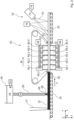
- FIG 1 shows schematically an OSB board manufacturing device 10 according to the invention, which has a coarse chip manufacturing device 12.
- the coarse chip manufacturing device 12 comprises a debarker 14 for debarking wood 16, a coarse chipper 16 arranged behind the debarker 14 in the material flow direction M and a dryer 18 arranged behind it in the material flow direction M.
- the coarse chips 20.i produced in this way are spread by a schematically drawn distribution device 21 to form a coarse chip layer 22 on a belt conveyor 24 and are wetted with a flame retardant solution 28 by means of a flame retardant solution application device 26.
- a pressure difference is then applied to the coarse chip layer 22 by means of a pressure difference generator 30 so that the flame retardant solution 28 penetrates into the coarse chips 20.i. This creates coarse chips 32.i containing flame retardants.
- the coarse chips 32.i. containing flame retardants are glued using a gluing device 33.
- the gluing device 33 can be, for example, a mixer or a coil, i.e. a rotating drum.
- the glued coarse chips 32.i are spread by a first spreading head 34.1 to form a first cover layer 36.1.
- a middle layer spreader 38 spreads a middle layer 40 onto the first cover layer 20.1.
- a second cover layer 36.2 is spread onto the middle layer 40 using a second spreading head 34.2.
- the layers 36.1, 40, 36.2 are pressed into an OSB board 44 using a hot press 42.
- the middle layer spreader 38 spreads middle layer chips 46.i, which are either produced by means of a middle chip production device or separated from the coarse chips 20.i by sieving using a classifier 48, which is present in this case.
- the middle layer chips 46.i are then glued in a second hopper 50 and subsequently conveyed to the middle layer spreader 38.
- FIG. 2 shows the distribution device 21, the flame retardant solution application device 26 and the pressure difference generator 30.
- the flame retardant solution application device 26 has a reservoir 50 in which the flame retardant solution 28 is contained.
- the flame retardant solution 28 can be brought to a predetermined temperature T 28 , for which, for example, 50°C ⁇ T 28 ⁇ 95°C applies.
- the flame retardant solution 28 is guided to nozzles 56.k, which are arranged next to one another transversely to the material flow direction M, and from there sprayed onto the coarse chip layer 22.
- a pressure p j of, for example, 100 hPa ⁇ p j ⁇ 800 hPa is therefore present at the suction chambers 60.j. It is possible that the pressures in the individual suction chambers 60.j differ from one another.
- the suction chambers 60.j are located on a conveyor belt 62 of the belt conveyor 24, which has openings, for example holes. As a result, the pressure p j is applied to the coarse chip layer 22.
- the differential pressure generator 30, as in Figure 2 shown has a perforated metal band 64 which presses onto the coarse chip layer 22 from above.
- Pressure rollers 66.1, 66.2 are provided for this purpose, for example.
- the suction chambers 60.j lie against the metal band 64 on the side of the metal band 64 facing away from the coarse chip layer 22.
- an introduction pressure p 22 of, for example, 100 hPa ⁇ p 22 ⁇ 800 hPa therefore prevails in the coarse chip layer 22.
- the differential pressure generator 30, as in Figure 2 shown has two sets of suction chambers 60.j and 60 ⁇ .j, between which the coarse chip layer 22 is arranged. It is possible, but not necessary, that the second set of suction chambers 60 ⁇ .j is connected to a second pump 68.
- the second pump 68 can be a vacuum pump or a pressure pump.
- the pressure p j in the first set of suction chambers 60.j is an overpressure and the pressure p' j in the second set of suction chambers 60 ⁇ .j is an overpressure.
- the pressure p j is an overpressure and the pressure p' j is a negative pressure.
- the pressure p j is a negative pressure and the pressure p' j is a negative pressure.
- the pressure p j is a negative pressure and the pressure p' j is a positive pressure.
- An inspection system 70 having a camera 72 can be arranged in the material flow direction M behind the pressure difference generator 30.
- the camera 72 detects light that is emitted or not absorbed by a dye in the flame retardant solution 28. Alternatively or additionally, the camera 72 detects fluorescent light. In this way, an actual flame retardant distribution k ist (x,y) is determined, which indicates a concentration k of flame retardant depending on the area coordinates x, y.
- a control 74 compares the actual flame retardant distribution k ist (x,y) with a target flame retardant distribution k soll (x,y) and controls the nozzles 56.k individually so that a deviation between the actual flame retardant distribution k ist (x,y) and the target flame retardant distribution k soll (x,y) is minimized.
- the inspection system it is possible, but not necessary, for the inspection system to have a UV light source 76 that illuminates the coarse chip layer 22 in a field of view G of the camera 72.
- the field of view G is the area of the coarse chip layer 22 that is recorded by the camera 72.
- the inspection system 70 is in Figure 1 not shown for clarity.
- Figure 1 shows that a cutting device 78 can be arranged behind the hot press 42 in the direction of material flow, which divides the OSB board 44 into individual board segments 80.1.
- a second inspection system 82 is arranged, the camera 84 of which records a cut surface 86 of the respective board segment 80.1.
- a second actual flame retardant distribution k ist,2 (y,z) is determined, which also encodes the depth dependence of the concentration k of flame retardant.
- the second actual flame retardant distribution k ist,2 (y,z) encodes a depth profile of the dye.
- the control 74 is designed to change the pressures p j in the at least one suction chamber 60.j and/or a conveyor belt speed v 62 of the conveyor belt 62, so that the second actual flame retardant distribution k ist,2 (y,z) approaches a second target flame retardant distribution k soll,2 (y,z).
- OSB board manufacturing device Conveyor belt 12 Coarse chip production device 64 Metal band 14 Debarker 66 Pressure roller 16 Wood 68 second pump 18 dryer 70 Inspection system 20 Coarse chips 72 camera 21 Distribution device 74 regulation 22 Coarse chip layer 76 UV light source 24 Belt conveyor 78 Cutting device 26 Flame retardant solution dispensing device 80 Plate segment 28 Flame retardant solution 82 second inspection system 84 second camera 30 Pressure difference generator 86 Cutting surface 32 coarse chips containing flame retardants i Running index 33 Glueing device j Running index 34 Spreading head k concentration 36 Top layer k is (x,y) Actual flame retardant distribution 38 Middle layer spreader k should (x,y) Target flame retardant distribution 40 Middle class 42 Hot press k is,2 (y,z) second actual flame retardant distribution 44 OSB board 46 Middle layer chips k should,2 (y,z) second target flame retardant distribution 48 Classifier 50 reservoir M Material flow direction 52 Heating p Pressure 54 Dosing pump 56 jet 58 Vacuum pump 60 Suction chamber
Landscapes
- Life Sciences & Earth Sciences (AREA)
- Engineering & Computer Science (AREA)
- Manufacturing & Machinery (AREA)
- Wood Science & Technology (AREA)
- Forests & Forestry (AREA)
- Mechanical Engineering (AREA)
- Dry Formation Of Fiberboard And The Like (AREA)
Description
- Die Erfindung betrifft ein Verfahren zum Herstellen von OSB-Platten (oriented strand board), die auch als Grobspanplatten bezeichnet werden können. Gemäß einem zweiten Aspekt betrifft die Erfindung eine OSB-Platten-Herstellvorrichtung gemäß dem Oberbegriff von Anspruch 8.
- Es ist günstig, bei der Herstellung von schwerentflammbaren OSB-Platten möglichst wenig Flammschutzmittel verwenden zu müssen, da dieses einen beträchtlichen Kostenaufwand bedeutet. Ein Grund dafür ist, dass Flammschutzmittel selbst teuer ist. Zudem führt Flammschutzmittel dazu, dass mehr Leim verwendet werden muss, um die gleiche mechanische Festigkeit zu erhalten, wie eine nicht schwerentflammbare OSB-Platte, was ebenfalls unerwünscht ist. Zudem sind die meisten Flammschutzmittel schlecht wasserlöslich, sodass durch das Einbringen des Flammschutzmittels in die Späne zudem große Mengen Wasser eingetragen werden, die im weiteren Verarbeitungsprozess entfernt werden müssen.
- Aus der
US 2003/0059638 A1 ist bekannt, OSB-Strands zunächst mit einem Flamm Schutzmittel zu besprühen und danach mittels einer Vakuum-und/oder Druckbehandlung in einem Behälter zu behandeln. Ein derartiges Verfahren wird im Chargenbetrieb durchgeführt. - Aus der
WO 03/099533 A1 - Die
EP 2 241 426 A1 beschreibt ein Verfahren zur Herstellung von mitteldichten Faserplatten oder hochdichten Faserplatten, bei dem das Fasermaterial zu einem Faserkuchen gestreut und mittels einer vor Presse komprimiert wird. Danach wird Flammschutzmittel auf den Faserkuchen aufgebracht und mittels Vakuum in den Faserkuchen eingesogen und der so behandelte Faserkuchen unmittelbar danach mittels einer Bandpresse verpresst. - Die
US 146 766 beschreibt ein Verfahren, bei dem eine Mischung aus Natriumsilikat und -borat auf Holz aufgebracht und danach mittels Wärme ausgehärtet wird. So entsteht eine Wasser unlösliche Flammschutzschicht. - Der Erfindung liegt die Aufgabe zugrunde, die Herstellung von schwerentflammbaren OSB-Platten zu verbessern.
- Die Erfindung löst das Problem durch ein Verfahren zum Herstellen von OSB-Platten mit den Merkmalen von Anspruch 1. Gemäß einem zweiten Aspekt löst die Erfindung das Problem durch eine OSB-Platten-Herstellvorrichtung mit den Merkmalen von Anspruch 8.
- Vorteilhaft an der Erfindung ist, dass der Verbrauch an Flammschutzmittel in der Regel im Vergleich zu herkömmlich hergestellten OSB-Platten verringerbar ist. Dadurch, dass eine Druckdifferenz an die Grobspäne angelegt wird, wird die Flammschutzmittellösung zumindest teilweise in die Grobspäne eingesogen. Dadurch kommt es weniger zur Bildung einer Kruste aus Flammschutzmitteln auf den Grobspänen. Eine derartige Kruste würde bei der weiteren Verarbeitung, insbesondere beim mechanischen Transport und Streuen, leicht abgerieben und würde zu einem Verlust an Flammschutzmittel führen.
- Vorteilhaft ist zudem, dass durch das Anlegen der Druckdifferenz Flammschutzmittellösung in die Grobspäne eingesogen oder und/oder eingepresst werden kann. Es ist dann gemäß einer bevorzugten Ausführungsform möglich, auf den Grobspänen vorhandene Flammschutzmittellösung zu entfernen, das kann beispielsweise ein Absaugen oder Abschleudern sein. Dadurch wird weniger Wasser in die Grobspäne eingebracht als bei bekannten Verfahren. Es muss daher bei der weiteren Verarbeitung der Grobspäne weniger Wasser entfernt werden als bei bekannten OSB-Platten-Herstellverfahren.
- Häufig ist zudem günstig, dass es durch das Einsaugen und/oder Einpressen der Flammschutzmittellösung in die Grobspäne zu weniger chemischen Reaktionen mit dem Leim kommt. In der Regel muss daher die Leimmenge deutlich weniger gesteigert werden, um eine Festigkeitsverlust durch das Hinzufügen des Flammschutzmittels auszugleichen.
- Wenn - wie gemäß einer bevorzugten Ausführungsform vorgesehen - Flammschutzmittellösung, die beim Anlegen der Druckdifferenz von den Grobspänen abgeblasen und/oder abgesaugt wird, erneut auf die Grobspäne aufgebracht wird, vermindert sich zudem die Menge an Flammschutzlösung, die nicht in eine OSB-Platte eingebracht wird. Es ist günstig, wenn die Flammschutzmittellösung, die beim Anlegen der Druckdifferenz von den Grobspänen abgeblasen und/oder abgesaugt wird, vor dem erneuten Aufbringen gereinigt wird, beispielsweise durch Filtern oder Zentrifugieren. So werden beispielsweise etwaige Holzbestandteile aus der Flammschutzmittellösung abgetrennt.
- Insbesondere handelt es sich bei dem erfindungsgemäßen Verfahren um ein Verfahren zum Herstellen von schwerentflammbaren OSB-Platten nach DIN EN 13823 (single burner item) oder ist schwer entflammbar nach DIN EN 13501-1.
- Bei der Flammschutzmittellösung handelt es sich vorzugsweise um eine wässrige Lösung. Die Flammschutzmittellösung enthält vorzugsweise zumindest eine organische oder anorganische phosphorhaltige und/oder stickstoffhaltige Verbindung.
- Unter dem Aufbringen der Flammschutzmittellösung auf die Grobspäne wird insbesondere ein Aufsprühen oder Aufdüsen verstanden.
- Unter dem Anlegen der Druckdifferenz an die Grobspäne wird gemäß einer ersten Ausführungsform verstanden, dass eine Druckdifferenz zwischen einer ersten Seitenfläche der Grobspäne und der gegenüberliegenden Seitenfläche der Grobspäne erzeugt wird. Die beiden Seitenflächen sind um die Höhe des Grobspans voneinander entfernt, die 0,5 ± 0,2 Zentimeter beträgt.
- Unter dem Anlegen der Druckdifferenz an die Grobspäne wird gemäß einer zweiten Ausführungsform verstanden, dass an die Grobspäne, insbesondere an die Grobspanschicht, ein Druck angelegt wird, der sich vom Umgebungsdruck, insbesondere um zumindest 200 hPa, vorzugsweise zumindest 400 hPa, besonders bevorzugt zumindest 600 hPa, unterscheidet. Es kann sich bei dem Druck um einen Überdruck oder einen Unterdruck handeln.
- Unter dem Merkmal, dass die Grobspäne verpresst werden, sodass die OSB-Platte entsteht, wird insbesondere verstanden, dass zumindest die Grobspäne verpresst werden. Insbesondere ist es möglich, dass zudem weitere Späne, die keine Grobspäne sind, mit den Grobspänen verpresst werden. Zudem ist es möglich und stellt eine bevorzugte Ausführungsform dar, dass aus den Grobspänen eine erste Deckschicht und eine zweite Deckschicht gestreut werden und mit einer Mittelschicht, die zwischen den beiden Deckschichten angeordnet ist, zur OSB-Platte verpresst werden.
- Das Beleimen erfolgt vorzugsweise ohne an den Grobspänen anliegende Druckdifferenz.
- Durch die Schritte (a) Anordnen der Grobspäne auf einem Transportband, sodass eine Grobspanschicht entsteht, und (b) Aufbringen der Flammschutzmittellösung auf die Grobspanschicht können die Grobspäne schnell, homogen und Prozess sicher mit Flammschutzmittellösung benetzt werden.
- Beispielsweise ist das Anlegen der Druckdifferenz an die mit Flammschutzmittellösung besetzten Grobspäne ein Anlegen eines Unterdrucks an eine Unterseite des Transportbands. Das Transportband ist dazu gasdurchlässig. Beispielsweise ist das Transportband perforiert oder aus einem gasdurchlässigen Material aufgebaut, beispielsweise einem Textil. Alternativ kann das Transportband ein Metallband sein. Dieses Metallband ist vorzugsweise perforiert.
- Alternativ oder zusätzlich ist das Anlegen der Druckdifferenz an die mit Flammschutzmittellösung benetzten Grobspäne ein Anlegen eines Überdrucks an eine Oberseite der Grobspanschicht. Das erfolgt beispielsweise dadurch, dass die Grobspanschicht zunächst eine Walze passiert, die als Abdichtung fungiert, und dann in einen Überdruckbereich eintritt, in dem der Überdruck anliegt. Die Grobspanschicht liegt auf einem gasdurchlässigen Förderband, auf dessen dem Überdruckbereich abgewandte Seite ein geringerer Druck, beispielsweise Umgebungsdruck oder Unterdruck, anliegt. Die Grobspanschicht verlässt den Überdruckbereich, indem sie eine Walze passiert, die als Dichtung wirkt.
- Das Verfahren des Herstellens der Grobspäne umfasst ein Trocknen der Grobspäne. In anderen Worten werden die Grobspäne vor dem Aufbringen der Flammschutzmittellösung getrocknet. Das Trocknen kann auf dem gleichen Transportband erfolgen wie das Aufbringen der Flammschutzmittellösung und gegebenenfalls das Anlegen der Druckdifferenz, das ist aber nicht notwendig. Vorzugsweise werden die Grobspäne getrocknet, bis sie darrtrocken sind. In diesem Zustand wird besonders leicht und schnell Flammschutzmittellösung von den getrockneten Grobspänen aufgenommen. Gemäß einer bevorzugten Ausführungsform werden die flammschutzmittelhaltigen Grobspäne nicht wesentlich getrocknet. Hierunter ist insbesondere zu verstehen, dass die flammschutzmittelhaltigen Grobspäne vor dem Beleimen und/oder nach dem Beleimen und vor dem Verpressen sich in ihrem Feuchtegehalt um höchstens fünf Prozentpunkte, insbesondere um höchstens zwei Prozentpunkte, ändert.
- Vorzugsweise hat die Grobspanschicht eine Spanschichtdicke, die höchstens dem vierfachen, vorzugsweise höchstens dem dreifachen, bevorzugt höchstens dem Doppelten, einer Grobspanlagendicke einer einzelnen Grobspanlage entspricht. Die Grobspanlagendicke ist die minimal erreichbare Dicke einer Grobspanlage. Diese ist die mittlere Höhe einer Anordnung von Grobspänen auf einer ebenen, horizontal verlaufenden Testfläche von 1 m2, wobei für diese Anordnung gilt, dass auf höchstens 75 % der Testfläche Abschnitte von zwei oder mehr Grobspänen übereinanderliegen und wobei zumindest 90%, vorzugsweise zumindest 95%, insbesondere 100%, der Testfläche von Grobspänen bedeckt sind.
- Vorzugsweise hat die Flammschutzmittellösung beim Aufbringen auf die Grobspanschicht eine Temperatur von zumindest 50°, vorzugsweise von zumindest 60°, insbesondere von zumindest 70 °C. Eine hohe Temperatur erhöht in der Regel die Löslichkeit des Flammschutzmittels in dem Lösungsmittel, sodass weniger Lösungsmittel, in der Regel Wasser, notwendig ist, um eine vorgegebene Menge an Flammschutzmittel zu lösen. Zudem sinkt die Viskosität von Wasser mit zunehmender Temperatur, sodass die Flammschutzmittellösung leichter in die Grobspäne eindringen kann.
- Günstig ist es, wenn die Flammschutzmittellösung eine Konzentration an Flammschutzmittel enthält, die zumindest 60 %, insbesondere zumindest 70 %, vorzugsweise zumindest 80 %, besonders bevorzugt zumindest 90 %, der maximalen Löslichkeit des Flammschutzmittels entspricht.
- Vorzugsweise enthält die Flammschutzmittellösung einen Viskositätssenker. Alternativ oder zusätzlich enthält die Flammschutzmittellösung vorzugsweise ein Tensid. Das Verbessert die Benetzung der Grobspäne.
- Günstig ist es, wenn das Verfahren die folgenden Schritte aufweist: (a) Herstellen von Grob-und Mittelschichtspänen, (b) gemeinsames Trocknen der Grobspäne und der Mittelschichtspäne, (c) Trennen von Grobspänen und Mittelschichtspänen, (d) Aufbringen der Flammschutzmittellösung insbesondere auf die Grobspäne, vorzugsweise nur auf die Grobspäne, (e) Herstellen einer ersten Deckschicht und einer zweiten Deckschicht aus den flammschutzmittelhaltigen Grobspänen und einer Mittelschicht zumindest auch aus den Mittelschichtspänen und (f) Verpressen von erster Deckschicht, zweiter Deckschicht und Mittelschicht zur OSB-Platte. Auf diese Weise wird eine OSB-Platte erhalten, die einerseits schwerentflammbar ist und andererseits nicht mehr Flammschutzmittel enthält als notwendig ist.
- Vorzugsweise weist die Flammschutzmittellösung einen Farbstoff auf. Dieser ist im sichtbaren Bereich farblos. In diesem Fall kann der Farbstoff auch als Marker bezeichnet werden. Günstig ist es, wenn der Farbstoff im UV-Bereich absorbiert und/oder fluoresziert. In diesem Fall kann durch Bestrahlen mit UV-Licht und/oder Aufnehmen eines Bildes der Grobspanschicht und/oder der OSB-Platte mit einer im UV-Bereich empfindlichen Kamera eine Flammschutzmittelverteilung der Flammschutzmittellösung und/oder des Flammschutzmittels erfasst werden. Anhand der Flammschutzmittelverteilung kann dann gemäß einer bevorzugten Ausführungsform ein Prozessparameter in Form der Transportbandgeschwindigkeit des Transportbands und oder der Druckdifferenz und/oder einer flächenspezifischen Ausbringmenge an Flammschutzmittellösung geregelt werden. In anderen Worten wird eine Abweichung zwischen einer Soll-Flammschutzmittelverteilung und der jeweils gemessenen Ist-Flammschutzmittelverteilung ermittelt und zumindest einer der genannten Parameter so geregelt werden, dass die Abweichung minimiert wird.
- Eine erfindungsgemäße OSB-Platten-Herstellvorrichtung besitzt vorzugsweise ein Inspektionssystem zum Erfassen der Flammschutzmittelverteilung an Flammschutzmittel in der Grobspanschicht. Es kann sich hierbei um die Verteilung des Flammschutzmittels in der Fläche der Grobspanschicht handeln, also um die zweidimensionale Verteilung in Längsrichtung und Breitenrichtung der Grobspanschicht, nicht aber in Dickenrichtung.
- Alternativ oder zusätzlich kann das Inspektionssystem ausgebildet sein zum Erfassen der Flammschutzmittelverteilung in der OSB-Platte. Es kann sich dann um die Verteilung des Flammschutzmittels in der Fläche der OSB-Platte handeln, also um die zweidimensionale Verteilung in Längsrichtung und Breitenrichtung der Grobspanschicht und/oder der Verteilung des Flammschutzmittels in Dickenrichtung.
- Das Inspektionssystem besitzt vorzugsweise eine Kamera zum Erfassen von UV-Licht und/oder Fluoreszenzlicht, das beim Bestrahlen der Grobspanschicht bzw. der OSB-Platte mit UV-Licht entsteht. Vorzugsweise besitzt das Inspektionssystem zudem eine UV-Lichtquelle zum Bestrahlen der Grobspanschicht bzw. der OSB-Platte mit UV-Licht.
- Vorzugsweise besitzt der Differenzdruckerzeuger eine Unterdruckpumpe und zumindest eine Saugkammer, vorzugsweise zumindest zwei Saugkammern, insbesondere eine Mehrzahl an Saugkammern, die jeweils über ein Ventil mit der Unterdruckpumpe verbunden sind. Die Ventile sind vorzugsweise ausgebildet zum Vergrößern ihres Ventilöffnungsgrads bei abnehmendem Druck in der Saugkammer. In anderen Worten öffnen die Ventile umso weiter, je kleiner der Druck in der jeweiligen Saugkammer ist.
- Die Saugkammern sind so angeordnet, dass zumindest 90 % der Fläche, vorzugsweise zumindest 95% der Fläche, besonders bevorzugt 100% der Fläche der Grobspanlage für zumindest eine vorgegebene Zeit von beispielsweise 1 Sekunde, insbesondere zumindest 5 Sekunden, mittels zumindest jeweils einer Saugkammer mit der Druckdifferenz, im vorliegenden Fall mit einem Unterdruck, beaufschlagbar ist.
- Vorzugsweise beträgt ein Unterdruck zumindest 300 hPa (und der Druck somit und 713 hPa), insbesondere zumindest 500 hPa (und der Druck somit und 513 hPa).
- Im Folgenden wird die Erfindung anhand der beigefügten Zeichnungen näher erläutert. Dabei zeigt
- Figur 1
- eine schematische Ansicht einer erfindungsgemäßen OSB-Platten-Herstellvorrichtung zum Durchführen eines erfindungsgemäßen Verfahrens und
- Figur 2
- eine schematische Detailansicht der OSB-Platten-Herstellvorrichtung gemäß
Figur 1 . -
Figur 1 zeigt schematisch eine erfindungsgemäße OSB-Platten-Herstellvorrichtung 10, die eine Grobspan-Herstellvorrichtung 12 aufweist. Die Grobspan-Herstellvorrichtung 12 umfasst einen Entrinder 14 zum Entrinden von Holz 16, einen in Materialflussrichtung M hinter dem Entrinder 14 angeordneten Grobzerspaner 16 und einen in Materialflussrichtung M dahinter angeordneten Trockner 18. Die Grobspan-Herstellvorrichtung 12 erzeugt so Grobspäne 20.i (i = 1, 2, 3, ...). - Die so erzeugten Grobspäne 20.i werden von einer schematisch eingezeichneten Verteilvorrichtung 21 zu einer Grobspanschicht 22 auf einen Bandförderer 24 gestreut und mittels einer Flammschutzmittellösung-Ausbringvorrichtung 26 mit einer Flammschutzmittellösung 28 benetzt. Nachfolgend wird mittels eines Druckdifferenzerzeugers 30 eine Druckdifferenz an die Grobspanschicht 22 angelegt, sodass die Flammschutzmittellösung 28 in die Grobspäne 20.i eindringt. So entstehen flammschutzmittelhaltigen Grobspäne 32.i.
- Die flammschutzmittelhaltigen Grobspäne 32.i. werden mittels einer Beleimvorrichtung 33 beleimt. Die Beleimvorrichtung 33 kann beispielsweise ein Mischer oder ein Coil, also eine rotierende Trommel, sein.
- Die beleimten Grobspäne 32.i werden von einem ersten Streukopf 34.1 zu einer ersten Deckschicht 36.1 gestreut. Mittels eines Mittelschichtstreuers 38 wird eine Mittelschicht 40 auf die erste Deckschicht 20.1 gestreut. Auf die Mittelschicht 40 wird mittels eines zweiten Streukopfs 34.2 eine zweite Deckschicht 36.2 gestreut. Mittels einer Heißpresse 42 werden die Schichten 36.1, 40, 36.2 zu einer OSB-Platte 44 verpresst.
- Der Mittelschichtstreuer 38 streut Mittelschichtspäne 46.i, die entweder mittels einer Mittelspan-Herstellvorrichtung hergestellt werden oder durch Sieben mittels einem in diesem Fall vorhandenen Klassierer 48 von den Grobspänen 20.i getrennt. Nachfolgend werden die Mittelschichtspäne 46.i in einem zweiten Beleimer 50 beleimt und nachfolgend zum Mittelschichtstreuers 38 gefördert.
-
Figur 2 zeigt die Verteilvorrichtung 21, die Flammschutzmittellösung-Ausbringvorrichtung 26 und den Druckdifferenzerzeuger 30. Die Flammschutzmittellösung-Ausbringvorrichtung 26 weist ein Reservoir 50 auf, in dem die Flammschutzmittellösung 28 enthalten ist. Mittels einer Heizung 52 kann die Flammschutzmittellösung 28 auf eine vorgegebene Temperatur T28 gebracht werden, für die beispielsweise 50°C ≤ T28 ≤ 95°C gilt. Mittels einer Dosierpumpe 54 wird die Flammschutzmittellösung 28 zu Düsen 56.k geleitet, die quer zur Materialflussrichtung M nebeneinander angeordnet sind, und von dort auf die Grobspanschicht 22 gesprüht. - Der Druckdifferenzerzeuger 30 besitzt eine Unterdruckpumpe 58, die mit einer Mehrzahl an Saugkammer 60.j (j = 1, 2, ...) verbunden ist. Beim Betrieb der Unterdruckpumpe 58 liegt daher an den Saugkammern 60.j ein Druck pj von beispielsweise 100 hPa ≤ pj ≤ 800 hPa an. Es ist dabei möglich, dass sich die Drücke in den einzelnen Saugkammern 60.j voneinander unterscheiden.
- Die Saugkammern 60.j liegen an einem Transportband 62 des Bandförderer 24 an, das Öffnungen, beispielsweise Löcher, aufweist. Dadurch liegt der Druck pj an der Grobspanschicht 22 an.
- Es ist möglich, nicht aber notwendig, dass der Differenzdruckerzeuger 30, wie in
Figur 2 gezeigt, ein perforiertes Metallband 64 aufweist, das von oben auf die Grobspanschicht 22 drückt. Dazu sind beispielsweise Druckrollen 66.1, 66.2 vorhanden. Die Saugkammern 60.j liegen an dem Metallband 64 auf der der Grobspanschicht 22 abgewandten Seite des Metallbands 64 an. Im Bereich der Druckkammern 60.j herrscht daher in der Grobspanschicht 22 ein Einbringdruck p22 von beispielsweise 100 hPa ≤ p22 ≤ 800 hPa. - Es ist zudem möglich, nicht aber notwendig, dass der Differenzdruckerzeuger 30, wie in
Figur 2 gezeigt, zwei Sätze an Saugkammer 60.j und 60`.j aufweist, zwischen denen die Grobspanschicht 22 angeordnet ist. Es ist möglich, nicht aber notwendig, dass der zweite Satz an Saugkammern 60`.j mit einer zweiten Pumpe 68 verbunden ist. Die zweite Pumpe 68 kann eine Vakuumpumpe oder eine Druckpumpe sein. - Es ist möglich, dass der Druck pj im ersten Satz an Saugkammern 60.j ein Überdruck ist und der Druck p'j im zweiten Satz an Saugkammern 60`.j ein Überdruck.
- Alternativ ist möglich, dass der Druck pj ein Überdruck ist und der Druck p'j ein Unterdruck.
- Wiederum alternativ ist möglich, dass der Druck pj ein Unterdruck ist und der Druck p'j ein Unterdruck.
- Wiederum alternativ ist möglich, dass der Druck pj ein Unterdruck ist und der Druck p'j ein Überdruck.
- In Materialflussrichtung M hinter dem Druckdifferenzerzeuger 30 kann ein Inspektionssystem 70 angeordnet sein, das eine Kamera 72 aufweist. Mit der Kamera 72 wird Licht erfasst, das von einem Farbstoff in der Flammschutzmittellösung 28 emittiert oder nicht absorbiert wird. Alternativ oder zusätzlich wird mit der Kamera 72 Fluoreszenzlicht erfasst. Auf diese Weise wird eine Ist-Flammschutzmittelverteilung kist(x,y) ermittelt, die eine Konzentration k an Flammschutzmittel in Abhängigkeit von den Flächenkoordinaten x, y angibt. Eine Regelung 74 vergleicht die Ist-Flammschutzmittelverteilung kist(x,y) mit einer Soll-Flammschutzmittelverteilung ksoll(x,y) und steuert die Düsen 56.k individuell so an, dass eine Abweichung zwischen Ist-Flammschutzmittelverteilung kist(x,y) und Soll-Flammschutzmittelverteilung ksoll(x,y) minimiert wird.
- Es ist möglich, nicht aber notwendig, dass das Inspektionssystem eine UV-Lichtquelle 76 aufweist, die die Grobspanschicht 22 in einem Gesichtsfeld G der Kamera 72 beleuchtet. Das Gesichtsfeld G ist derjenige Bereich der Grobspanschicht 22, die mittels der Kamera 72 aufgenommen wird. Das Inspektionssystem 70 ist in
Figur 1 der Übersichtlichkeit wegen nicht eingezeichnet. -
Figur 1 zeigt, dass in Materialflussrichtung hinter der Heißpresse 42 eine Schneidevorrichtung 78 angeordnet sein kann, die die OSB-Platte 44 in einzelne Plattensegmente 80.1 zerteilt. In diesem Fall ist es vorteilhaft, wenn ein zweites Inspektionssystem 82 angeordnet ist, dessen Kamera 84 eine Schnittfläche 86 des jeweiligen Plattensegments 80.1 aufnimmt. Daraus wird eine zweite Ist-Flammschutzmittelverteilung kist,2(y,z) ermittelt, die auch die Tiefenabhängigkeit der Konzentration k an Flammschutzmittel kodiert. In anderen Worten kodiert die zweite Ist-Flammschutzmittelverteilung kist,2(y,z) einen Tiefenverlauf des Farbstoffs. - Die Regelung 74 ist ausgebildet zum Verändern der Drücke pj in der zumindest einen Saugkammer 60.j und/oder einer Transportbandgeschwindigkeit v62 des Transportbands 62, sodass sich die zweite Ist-Flammschutzmittelverteilung kist,2(y,z) einer zweiten Soll-Flammschutzmittelverteilung ksoll,2(y,z) annähert.
-
10 OSB-Platten-Herstellvorrichtung 62 Transportband 12 Grobspan-Herstellvorrichtung 64 Metallband 14 Entrinder 66 Druckrolle 16 Holz 68 zweite Pumpe 18 Trockner 70 Inspektionssystem 20 Grobspäne 72 Kamera 21 Verteilvorrichtung 74 Regelung 22 Grobspanschicht 76 UV-Lichtquelle 24 Bandförderer 78 Schneidevorrichtung 26 Flammschutzmittellösung-Ausbringvorrichtung 80 Plattensegment 28 Flammschutzmittellösung 82 zweites Inspektionssystem 84 zweite Kamera 30 Druckdifferenzerzeuger 86 Schnittfläche 32 flammschutzmittelhaltige Grobspäne i Laufindex 33 Beleimvorrichtung j Laufindex 34 Streukopf k Konzentration 36 Deckschicht kist (x,y) Ist-Flammschutzmittelver-teilung 38 Mittelschichtstreuer ksoll (x,y) Soll-Flammschutzmittelver-teilung 40 Mittelschicht 42 Heißpresse kist,2(y,z) zweite Ist-Flammschutz-mittelverteilung 44 OSB-Platte 46 Mittelschichtspänen ksoll,2(y,z) zweite Soll-Flammschutz-mittelverteilung 48 Klassierer 50 Reservoir M Materialflussrichtung 52 Heizung p Druck 54 Dosierpumpe 56 Düse 58 Unterdruckpumpe 60 Saugkammer
Claims (13)
- Verfahren zum Herstellen von OSB-Platten (44) mit den Schritten:(a) Herstellen von Grobspänen (20), das ein Trocknen der Grobspäne (20) umfasst,(b) Anordnen der Grobspäne (20) auf einem Transportband (62), sodass eine Grobspanschicht (22) entsteht,(c) Aufbringen einer Flammschutzmittellösung (28) auf die auf dem Transportband (62) liegenden Grobspäne (20),(d) Anlegen einer Druckdifferenz an die mit Flammschutzmittellösung (28) benetzten Grobspäne (20) zum Einbringen von Flammschutzmittellösung (28) in die Grobspäne (20), sodass flammschutzmittelhaltige Grobspäne (32) entstehen, durch Anlegen
eines Unterdrucks an eine Unterseite des Transportbands und/oder eines Überdrucks auf eine Oberseite der Grobspanschicht (22),(e) danach Beleimen der flammschutzmittelhaltigen Grobspäne (32), sodass beleimte Grobspäne (20) entstehen, und(f) Verpressen der Grobspäne (20), sodass die OSB-Platte (44) entsteht(g) wobei das Trocknen der Grobspäne (20) vor dem Aufbringen der Flammschutzmittellösung (28) erfolgt. - Verfahren nach Anspruch 1, gekennzeichnet durch den Schritt Entfernen von auf den Grobspänen vorhandener Flammschutzmittellösung.
- Verfahren nach Anspruch 2, dadurch gekennzeichnet, dass Flammschutzmittellösung(a) durch Anlegen einer Druckdifferenz von den Grobspänen abgeblasen und/oder abgesaugt wird und(b) erneut auf die Grobspäne aufgebracht wird.
- Verfahren nach einem der vorstehenden Ansprüche, dadurch gekennzeichnet, dass die flammschutzmittelhaltigen Grobspäne vor dem Beleimen und/oder nach dem Beleimen und vor dem Verpressen sich in ihrem Feuchtegehalt um höchstens fünf Prozentpunkte ändern.
- Verfahren nach einem der vorstehenden Ansprüche, dadurch gekennzeichnet, dass die Flammschutzmittellösung (28)(a) beim Aufbringen auf die Grobspanschicht (22) eine Temperatur von zumindest 50°C hat und/oder(b) einen Viskositätssenker enthält.
- Verfahren nach einem der vorstehenden Ansprüche mit den Schritten:(a) Herstellen von Grob- und Mittelschichtspänen,(b) gemeinsames Trocknen der Grob- und Mittelschichtspäne,(c) Trennen von Grob- und Mittelschichtspänen,(d) Einbringen des Flammschutzmittels auf die Grobspäne (20), sodass flammschutzmittelhaltige Grobspäne (32) entstehen,(e) Herstellen einer ersten Deckschicht (36.1) und einer zweiten Deckschicht (36.2) aus den flammschutzmittelhaltigen Grobspänen (32) und einer Mittelschicht (40) zumindest auch aus den Mittelschichtspänen (46) und(f) Verpressen von erster Deckschicht (36.1), zweiter Deckschicht (36.2) und Mittelschicht (40) zur OSB-Platte (44).
- Verfahren nach einem der vorstehenden Ansprüche 2 bis 6, dadurch gekennzeichnet, dass(a) die Flammschutzmittellösung (28) einen im sichtbaren Bereich farblosen und im UV-Bereich absorbierenden oder fluoreszierenden Farbstoff aufweist und(b) das Verfahren die folgenden Schritte aufweist:(i) tiefenabhängiges optisches Erfassen einer Farbstoffkonzentration der Grobspanschicht (22) und/oder der OSB-Platte (44), sodass ein Farbstoff-Tiefenverlauf erhalten wird, und(ii) Regeln einer Transportbandgeschwindigkeit, der Druckdifferenz und/oder einer flächenspezifischen Ausbringmenge an Flammschutzmittellösung (28) anhand des Farbstoff-Tiefenverlaufs.
- OSB-Platten-Herstellvorrichtung mit(a) einer Grobspan-Herstellvorrichtung (10) zum Herstellen von Grobspänen (20) aus Holz (16),(b) einem Trockner (18) zum Trocknen der Grobspäne (20), der mit der Grobspan-Herstellvorrichtung (10) verbunden ist,(c) einer Verteilvorrichtung (21) zum Verteilen der Grobspäne (20), sodass eine Grobspanschicht (22) entsteht, und(d) einem Bandförderer (24), der in Materialflussrichtung hinter dem Trockner (18) angeordnet ist, zum Fördern der Grobspanschicht (22),
gekennzeichnet durch(e) eine Flammschutzmittellösung-Aufbringvorrichtung (26), die in Materiaflussrichtung (M) hinter dem Trockner (18) angeordnet ist zum Aufbringen einer Flammschutzmittellösung (28) auf die Grobspanschicht (22), sodass flammschutzmittelhaltigen Grobspäne (32) entstehen,(f) einen Druckdifferenzerzeuger (30) zum Anlegen unter einer Druckdifferenz an die Grobspanschicht (22) und(g) eine in Materialflussrichtung (M) hinter der Flammschutzmittellösung-Aufbringvorrichtung (26) angeordnete Beleimvorrichtung (33) zum Beleimen der flammschutzmittelhaltigen Grobspäne (32). - OSB-Platten-Herstellvorrichtung nach Anspruch 8, gekennzeichnet durch ein Inspektionssystem (70) zum Erfassen einer Flammschutzmittelverteilung an Flammschutzmittel in der Grobspanschicht (22) und/oder in der OSB-Platte (44).
- OSB-Platten-Herstellvorrichtung nach Anspruch 9, dadurch gekennzeichnet, dass das Inspektionssystem (70)(a) eine UV-Lichtquelle (76) und(b) Kamera (72) zum Erfassen von reflektiertem UV-Licht und/oder Fluoreszenzlicht aufweist.
- OSB-Platten-Herstellvorrichtung nach Anspruch 9 oder 10, gekennzeichnet durch
eine Regelung (74), die ausgebildet ist zum automatischen Regeln einer Transportbandgeschwindigkeit, der Druckdifferenz und/oder einer flächenspezifischen Ausbringmenge an Flammschutzmittellösung (28) anhand der Flammschutzmittelverteilung. - OSB-Platten-Herstellvorrichtung nach einem der vorstehenden Ansprüche, dadurch gekennzeichnet, dass der Druckdifferenzerzeuger(a) eine Unterdruckpumpe (58) und(b) eine Mehrzahl an Saugkammern, die jeweils über ein Ventil mit der Unterdruckpumpe (58) verbunden sind, aufweist,(c) wobei die Ventile einen Ventilöffnungsgrad haben, der mit abnehmendem Druck (p) in der Saugkammern (60) zunimmt.
- OSB-Platten-Herstellvorrichtung nach einem der vorstehenden Ansprüche, dadurch gekennzeichnet, dass der Druckdifferenzerzeuger(a) eine Druckpumpe und(b) eine Mehrzahl an Druckkammern, die jeweils über ein Ventil mit der Druckpumpe verbunden sind, aufweist,(c) wobei die Ventile einen Ventilöffnungsgrad haben, der mit abnehmendem Druck (p) in der Saugkammer (60) zunimmt.
Priority Applications (8)
| Application Number | Priority Date | Filing Date | Title |
|---|---|---|---|
| EP22176340.2A EP4286149B1 (de) | 2022-05-31 | 2022-05-31 | Verfahren zum herstellen von osb-platten und osb-platten-herstellvorrichtung |
| PL22176340.2T PL4286149T3 (pl) | 2022-05-31 | 2022-05-31 | Sposób produkcji płyt osb i urządzenie do produkcji płyt osb |
| HUE22176340A HUE067706T2 (hu) | 2022-05-31 | 2022-05-31 | Eljárás OSB-lemezek elõállítására, valamint OSB-lemezeket elõállító berendezés |
| ES22176340T ES2983542T3 (es) | 2022-05-31 | 2022-05-31 | Procedimiento de fabricación de tableros OSB y dispositivo de fabricación de tableros OSB |
| PCT/EP2023/063944 WO2023232598A1 (de) | 2022-05-31 | 2023-05-24 | Verfahren zum herstellen von osb-platten und osb-platten-herstellvorrichtung |
| EP23728368.4A EP4532188A1 (de) | 2022-05-31 | 2023-05-24 | Verfahren zum herstellen von osb-platten und osb-platten-herstellvorrichtung |
| US18/866,421 US20250312941A1 (en) | 2022-05-31 | 2023-05-24 | Method for producing osb panels and osb panel production device |
| CN202380043672.8A CN119300970A (zh) | 2022-05-31 | 2023-05-24 | 用于生产osb面板的方法和osb面板生产装置 |
Applications Claiming Priority (1)
| Application Number | Priority Date | Filing Date | Title |
|---|---|---|---|
| EP22176340.2A EP4286149B1 (de) | 2022-05-31 | 2022-05-31 | Verfahren zum herstellen von osb-platten und osb-platten-herstellvorrichtung |
Publications (3)
| Publication Number | Publication Date |
|---|---|
| EP4286149A1 EP4286149A1 (de) | 2023-12-06 |
| EP4286149C0 EP4286149C0 (de) | 2024-05-01 |
| EP4286149B1 true EP4286149B1 (de) | 2024-05-01 |
Family
ID=81854844
Family Applications (2)
| Application Number | Title | Priority Date | Filing Date |
|---|---|---|---|
| EP22176340.2A Active EP4286149B1 (de) | 2022-05-31 | 2022-05-31 | Verfahren zum herstellen von osb-platten und osb-platten-herstellvorrichtung |
| EP23728368.4A Pending EP4532188A1 (de) | 2022-05-31 | 2023-05-24 | Verfahren zum herstellen von osb-platten und osb-platten-herstellvorrichtung |
Family Applications After (1)
| Application Number | Title | Priority Date | Filing Date |
|---|---|---|---|
| EP23728368.4A Pending EP4532188A1 (de) | 2022-05-31 | 2023-05-24 | Verfahren zum herstellen von osb-platten und osb-platten-herstellvorrichtung |
Country Status (7)
| Country | Link |
|---|---|
| US (1) | US20250312941A1 (de) |
| EP (2) | EP4286149B1 (de) |
| CN (1) | CN119300970A (de) |
| ES (1) | ES2983542T3 (de) |
| HU (1) | HUE067706T2 (de) |
| PL (1) | PL4286149T3 (de) |
| WO (1) | WO2023232598A1 (de) |
Families Citing this family (1)
| Publication number | Priority date | Publication date | Assignee | Title |
|---|---|---|---|---|
| CN118664709A (zh) * | 2024-06-25 | 2024-09-20 | 佳诺威集团(河南)科技有限公司 | 一种防潮难燃osb板生产装置及工艺 |
Family Cites Families (8)
| Publication number | Priority date | Publication date | Assignee | Title |
|---|---|---|---|---|
| SE465166B (sv) * | 1989-12-13 | 1991-08-05 | Fire Stop Lab Ab | Brandskyddande impregneringsloesning och anvaendning av densamma |
| US6146766A (en) * | 1998-03-20 | 2000-11-14 | Slimak; Karen Marie | Enhancing the strength, moisture resistance, and fire-resistance of wood, timber, lumber, similar plant-derived construction and building materials, and other cellulosic materials |
| US7371787B2 (en) * | 2000-04-14 | 2008-05-13 | Viance, Llc | Methods of incorporating treatment agents into wood based composite products |
| US6586109B2 (en) * | 2001-09-21 | 2003-07-01 | Premier Wood Treating, Llc | Fire retardant cellulose preservative treatment process |
| DE10222955C1 (de) * | 2002-05-24 | 2003-08-14 | Fraunhofer Ges Forschung | Verfahren zur Herstellung von OSB-Platten |
| ES2738596T3 (es) * | 2009-04-17 | 2020-01-23 | Flooring Technologies Ltd | Instalación para la fabricación de un tablero a base de madera |
| WO2012094723A1 (en) * | 2011-01-13 | 2012-07-19 | Blmh Technologies Inc. | Method for forming a fire resistant cellulose product, and associated apparatus |
| AU2011366162B2 (en) * | 2011-04-20 | 2015-06-04 | John Griem | Fire proof oriented strand board and its manufacture |
-
2022
- 2022-05-31 EP EP22176340.2A patent/EP4286149B1/de active Active
- 2022-05-31 HU HUE22176340A patent/HUE067706T2/hu unknown
- 2022-05-31 PL PL22176340.2T patent/PL4286149T3/pl unknown
- 2022-05-31 ES ES22176340T patent/ES2983542T3/es active Active
-
2023
- 2023-05-24 US US18/866,421 patent/US20250312941A1/en active Pending
- 2023-05-24 WO PCT/EP2023/063944 patent/WO2023232598A1/de not_active Ceased
- 2023-05-24 CN CN202380043672.8A patent/CN119300970A/zh active Pending
- 2023-05-24 EP EP23728368.4A patent/EP4532188A1/de active Pending
Also Published As
| Publication number | Publication date |
|---|---|
| HUE067706T2 (hu) | 2024-11-28 |
| CN119300970A (zh) | 2025-01-10 |
| EP4286149A1 (de) | 2023-12-06 |
| EP4286149C0 (de) | 2024-05-01 |
| EP4532188A1 (de) | 2025-04-09 |
| US20250312941A1 (en) | 2025-10-09 |
| ES2983542T3 (es) | 2024-10-23 |
| PL4286149T3 (pl) | 2024-08-26 |
| WO2023232598A1 (de) | 2023-12-07 |
Similar Documents
| Publication | Publication Date | Title |
|---|---|---|
| EP0695609B2 (de) | Verfahren zum Vorwärmen von Streugut auf eine vorgebbare Vorwärmtemperatur im Zuge der Herstellung von Holzwerkstoffplatten | |
| DE4333614C2 (de) | Verfahren und Anlage zur kontinuierlichen Herstellung von Spanplatten | |
| DE69511242T2 (de) | Verfahren zum herstellen von lignocelluloseplatten | |
| EP2623282B1 (de) | Verfahren zum Imprägnieren von Werkstoffplatten | |
| DE1224919B (de) | Verfahren und Vorrichtung zum Herstellen von pressbaren Faserplatten | |
| EP2942207B1 (de) | Verfahren zum Herstellen dekorierter Holzwerkstoffplatten und aus der Holzwerkstoffplatte hergestelltes Fußbodenpaneel | |
| EP0916460A1 (de) | Verfahren zum Kühlen von heissverpressten Platten, insbesondere Holzspan- und Faserplatten und Anlage zur Verfahrensdurchführung | |
| EP2168738B1 (de) | Verfahren zum Herstellen einer Holzfaserplatte | |
| EP3028829B1 (de) | Anlage zur herstellung einer holzwerkstoffplatte | |
| EP4378650B1 (de) | Verfahren zum herstellen von osb und osb-herstellvorrichtung | |
| EP4286149A1 (de) | Verfahren zum herstellen von osb-platten und osb-platten-herstellvorrichtung | |
| EP3461610B1 (de) | Verfahren und vorrichtung zur gezielten beeinflussung der technologischen eigenschaften einzelner bereiche einer holzwerkstoffplatte, eines vorverdichteten holzwerkstoffvlieses oder eines holzfaserkuchens | |
| DE10054002C2 (de) | Etagenpresse, insbesondere Einetagen- oder Mehretagenpresse | |
| EP4419304A1 (de) | Verfahren zur herstellung einer holzwerkstoffplatte und holzwerkstoffplatten-herstellvorrichtung | |
| DE10315922A1 (de) | Verfahren und Anlage zur Herstellung von Plattenwerkstoffen | |
| WO2019076556A1 (de) | Verfahren und vorrichtung zum herstellen einer holzwerkstoffplatte | |
| DE19750847C1 (de) | Verfahren zum Kühlen von heißverpressten Platten, insbesondere Holzspan- und Faserplatten und Kühlstrecke zur Verfahrensdurchführung | |
| EP3976331B1 (de) | Verfahren und vorrichtung zur vorwärmung einer pressgutmatte | |
| EP1747865B1 (de) | Verfahren und Vorrichtung zur Herstellung von Holzwerkstoffplatten | |
| DE3612703A1 (de) | Verfahren zur herstellung einer holzwerkstoffplatte | |
| DE102005016408A1 (de) | Verfahren zur kontinuierlichen Vorwärmung eines Vlieses oder einer Matte und Vorrichtung zur Durchführung des Verfahrens | |
| DE102024003345A1 (de) | Verfahren und Anlage zur Herstellung von Werkstoffplatten aus gestapelten flächigen Substraten | |
| WO2025133187A1 (de) | Verfahren zur herstellung einer werkstoffplatte | |
| DE102015107373A1 (de) | Verfahren und Vorrichtung zum Streuen eines Vlieses im Zuge der Herstellung von Werkstoffplatten und eine Werkstoffplatte | |
| DE202015102415U1 (de) | Vorrichtung zum Streuen eines Vlieses im Zuge der Herstellung von Werkstoffplatten und eine Werkstoffplatte |
Legal Events
| Date | Code | Title | Description |
|---|---|---|---|
| PUAI | Public reference made under article 153(3) epc to a published international application that has entered the european phase |
Free format text: ORIGINAL CODE: 0009012 |
|
| STAA | Information on the status of an ep patent application or granted ep patent |
Free format text: STATUS: REQUEST FOR EXAMINATION WAS MADE |
|
| 17P | Request for examination filed |
Effective date: 20230413 |
|
| AK | Designated contracting states |
Kind code of ref document: A1 Designated state(s): AL AT BE BG CH CY CZ DE DK EE ES FI FR GB GR HR HU IE IS IT LI LT LU LV MC MK MT NL NO PL PT RO RS SE SI SK SM TR |
|
| GRAP | Despatch of communication of intention to grant a patent |
Free format text: ORIGINAL CODE: EPIDOSNIGR1 |
|
| STAA | Information on the status of an ep patent application or granted ep patent |
Free format text: STATUS: GRANT OF PATENT IS INTENDED |
|
| INTG | Intention to grant announced |
Effective date: 20240115 |
|
| GRAS | Grant fee paid |
Free format text: ORIGINAL CODE: EPIDOSNIGR3 |
|
| GRAA | (expected) grant |
Free format text: ORIGINAL CODE: 0009210 |
|
| STAA | Information on the status of an ep patent application or granted ep patent |
Free format text: STATUS: THE PATENT HAS BEEN GRANTED |
|
| AK | Designated contracting states |
Kind code of ref document: B1 Designated state(s): AL AT BE BG CH CY CZ DE DK EE ES FI FR GB GR HR HU IE IS IT LI LT LU LV MC MK MT NL NO PL PT RO RS SE SI SK SM TR |
|
| REG | Reference to a national code |
Ref country code: GB Ref legal event code: FG4D Free format text: NOT ENGLISH |
|
| REG | Reference to a national code |
Ref country code: CH Ref legal event code: EP |
|
| REG | Reference to a national code |
Ref country code: DE Ref legal event code: R096 Ref document number: 502022000827 Country of ref document: DE |
|
| REG | Reference to a national code |
Ref country code: IE Ref legal event code: FG4D Free format text: LANGUAGE OF EP DOCUMENT: GERMAN |
|
| U01 | Request for unitary effect filed |
Effective date: 20240523 |
|
| U07 | Unitary effect registered |
Designated state(s): AT BE BG DE DK EE FI FR IT LT LU LV MT NL PT SE SI Effective date: 20240605 |
|
| U20 | Renewal fee for the european patent with unitary effect paid |
Year of fee payment: 3 Effective date: 20240711 |
|
| PG25 | Lapsed in a contracting state [announced via postgrant information from national office to epo] |
Ref country code: IS Free format text: LAPSE BECAUSE OF FAILURE TO SUBMIT A TRANSLATION OF THE DESCRIPTION OR TO PAY THE FEE WITHIN THE PRESCRIBED TIME-LIMIT Effective date: 20240901 |
|
| PG25 | Lapsed in a contracting state [announced via postgrant information from national office to epo] |
Ref country code: HR Free format text: LAPSE BECAUSE OF FAILURE TO SUBMIT A TRANSLATION OF THE DESCRIPTION OR TO PAY THE FEE WITHIN THE PRESCRIBED TIME-LIMIT Effective date: 20240501 |
|
| REG | Reference to a national code |
Ref country code: ES Ref legal event code: FG2A Ref document number: 2983542 Country of ref document: ES Kind code of ref document: T3 Effective date: 20241023 |
|
| PG25 | Lapsed in a contracting state [announced via postgrant information from national office to epo] |
Ref country code: NO Free format text: LAPSE BECAUSE OF FAILURE TO SUBMIT A TRANSLATION OF THE DESCRIPTION OR TO PAY THE FEE WITHIN THE PRESCRIBED TIME-LIMIT Effective date: 20240801 Ref country code: IS Free format text: LAPSE BECAUSE OF FAILURE TO SUBMIT A TRANSLATION OF THE DESCRIPTION OR TO PAY THE FEE WITHIN THE PRESCRIBED TIME-LIMIT Effective date: 20240901 Ref country code: HR Free format text: LAPSE BECAUSE OF FAILURE TO SUBMIT A TRANSLATION OF THE DESCRIPTION OR TO PAY THE FEE WITHIN THE PRESCRIBED TIME-LIMIT Effective date: 20240501 Ref country code: RS Free format text: LAPSE BECAUSE OF FAILURE TO SUBMIT A TRANSLATION OF THE DESCRIPTION OR TO PAY THE FEE WITHIN THE PRESCRIBED TIME-LIMIT Effective date: 20240801 |
|
| REG | Reference to a national code |
Ref country code: HU Ref legal event code: AG4A Ref document number: E067706 Country of ref document: HU |
|
| PG25 | Lapsed in a contracting state [announced via postgrant information from national office to epo] |
Ref country code: SK Free format text: LAPSE BECAUSE OF FAILURE TO SUBMIT A TRANSLATION OF THE DESCRIPTION OR TO PAY THE FEE WITHIN THE PRESCRIBED TIME-LIMIT Effective date: 20240501 |
|
| PG25 | Lapsed in a contracting state [announced via postgrant information from national office to epo] |
Ref country code: SM Free format text: LAPSE BECAUSE OF FAILURE TO SUBMIT A TRANSLATION OF THE DESCRIPTION OR TO PAY THE FEE WITHIN THE PRESCRIBED TIME-LIMIT Effective date: 20240501 |
|
| PG25 | Lapsed in a contracting state [announced via postgrant information from national office to epo] |
Ref country code: SM Free format text: LAPSE BECAUSE OF FAILURE TO SUBMIT A TRANSLATION OF THE DESCRIPTION OR TO PAY THE FEE WITHIN THE PRESCRIBED TIME-LIMIT Effective date: 20240501 Ref country code: SK Free format text: LAPSE BECAUSE OF FAILURE TO SUBMIT A TRANSLATION OF THE DESCRIPTION OR TO PAY THE FEE WITHIN THE PRESCRIBED TIME-LIMIT Effective date: 20240501 Ref country code: MC Free format text: LAPSE BECAUSE OF FAILURE TO SUBMIT A TRANSLATION OF THE DESCRIPTION OR TO PAY THE FEE WITHIN THE PRESCRIBED TIME-LIMIT Effective date: 20240501 |
|
| REG | Reference to a national code |
Ref country code: DE Ref legal event code: R097 Ref document number: 502022000827 Country of ref document: DE |
|
| PLBE | No opposition filed within time limit |
Free format text: ORIGINAL CODE: 0009261 |
|
| STAA | Information on the status of an ep patent application or granted ep patent |
Free format text: STATUS: NO OPPOSITION FILED WITHIN TIME LIMIT |
|
| 26N | No opposition filed |
Effective date: 20250204 |
|
| PG25 | Lapsed in a contracting state [announced via postgrant information from national office to epo] |
Ref country code: IE Free format text: LAPSE BECAUSE OF NON-PAYMENT OF DUE FEES Effective date: 20240531 |
|
| U20 | Renewal fee for the european patent with unitary effect paid |
Year of fee payment: 4 Effective date: 20250528 |
|
| PG25 | Lapsed in a contracting state [announced via postgrant information from national office to epo] |
Ref country code: GR Free format text: LAPSE BECAUSE OF FAILURE TO SUBMIT A TRANSLATION OF THE DESCRIPTION OR TO PAY THE FEE WITHIN THE PRESCRIBED TIME-LIMIT; INVALID AB INITIO Effective date: 20220531 |
|
| PG25 | Lapsed in a contracting state [announced via postgrant information from national office to epo] |
Ref country code: CY Free format text: LAPSE BECAUSE OF FAILURE TO SUBMIT A TRANSLATION OF THE DESCRIPTION OR TO PAY THE FEE WITHIN THE PRESCRIBED TIME-LIMIT; INVALID AB INITIO Effective date: 20220531 |
|
| PGFP | Annual fee paid to national office [announced via postgrant information from national office to epo] |
Ref country code: GB Payment date: 20260324 Year of fee payment: 5 |
|
| U20 | Renewal fee for the european patent with unitary effect paid |
Year of fee payment: 5 Effective date: 20260327 |
|
| REG | Reference to a national code |
Ref country code: CH Ref legal event code: U11 Free format text: ST27 STATUS EVENT CODE: U-0-0-U10-U11 (AS PROVIDED BY THE NATIONAL OFFICE) Effective date: 20260601 |
|
| PGFP | Annual fee paid to national office [announced via postgrant information from national office to epo] |
Ref country code: HU Payment date: 20260521 Year of fee payment: 5 |
|
| PGFP | Annual fee paid to national office [announced via postgrant information from national office to epo] |
Ref country code: ES Payment date: 20260618 Year of fee payment: 5 |
|
| PGFP | Annual fee paid to national office [announced via postgrant information from national office to epo] |
Ref country code: PL Payment date: 20260527 Year of fee payment: 5 |
|
| PGFP | Annual fee paid to national office [announced via postgrant information from national office to epo] |
Ref country code: RO Payment date: 20260529 Year of fee payment: 5 Ref country code: CH Payment date: 20260601 Year of fee payment: 5 |
|
| PGFP | Annual fee paid to national office [announced via postgrant information from national office to epo] |
Ref country code: CZ Payment date: 20260520 Year of fee payment: 5 Ref country code: TR Payment date: 20260521 Year of fee payment: 5 |