EP4286202A1 - Dedizierte dcdc-umwandlungseinheit zur bereitstellung von schlüsselfreien elektrischen lasten aus der antriebsbatterie in einem fahrzeug - Google Patents
Dedizierte dcdc-umwandlungseinheit zur bereitstellung von schlüsselfreien elektrischen lasten aus der antriebsbatterie in einem fahrzeug Download PDFInfo
- Publication number
- EP4286202A1 EP4286202A1 EP23176315.2A EP23176315A EP4286202A1 EP 4286202 A1 EP4286202 A1 EP 4286202A1 EP 23176315 A EP23176315 A EP 23176315A EP 4286202 A1 EP4286202 A1 EP 4286202A1
- Authority
- EP
- European Patent Office
- Prior art keywords
- battery
- key
- power
- dedicated
- conversion units
- Prior art date
- Legal status (The legal status is an assumption and is not a legal conclusion. Google has not performed a legal analysis and makes no representation as to the accuracy of the status listed.)
- Pending
Links
Images



Classifications
-
- H—ELECTRICITY
- H02—GENERATION; CONVERSION OR DISTRIBUTION OF ELECTRIC POWER
- H02M—APPARATUS FOR CONVERSION BETWEEN AC AND AC, BETWEEN AC AND DC, OR BETWEEN DC AND DC, AND FOR USE WITH MAINS OR SIMILAR POWER SUPPLY SYSTEMS; CONVERSION OF DC OR AC INPUT POWER INTO SURGE OUTPUT POWER; CONTROL OR REGULATION THEREOF
- H02M3/00—Conversion of DC power input into DC power output
-
- H—ELECTRICITY
- H02—GENERATION; CONVERSION OR DISTRIBUTION OF ELECTRIC POWER
- H02M—APPARATUS FOR CONVERSION BETWEEN AC AND AC, BETWEEN AC AND DC, OR BETWEEN DC AND DC, AND FOR USE WITH MAINS OR SIMILAR POWER SUPPLY SYSTEMS; CONVERSION OF DC OR AC INPUT POWER INTO SURGE OUTPUT POWER; CONTROL OR REGULATION THEREOF
- H02M3/00—Conversion of DC power input into DC power output
- H02M3/003—Constructional details, e.g. physical layout, assembly, wiring or busbar connections
-
- B—PERFORMING OPERATIONS; TRANSPORTING
- B60—VEHICLES IN GENERAL
- B60L—PROPULSION OF ELECTRICALLY-PROPELLED VEHICLES; SUPPLYING ELECTRIC POWER FOR AUXILIARY EQUIPMENT OF ELECTRICALLY-PROPELLED VEHICLES; ELECTRODYNAMIC BRAKE SYSTEMS FOR VEHICLES IN GENERAL; MAGNETIC SUSPENSION OR LEVITATION FOR VEHICLES; MONITORING OPERATING VARIABLES OF ELECTRICALLY-PROPELLED VEHICLES; ELECTRIC SAFETY DEVICES FOR ELECTRICALLY-PROPELLED VEHICLES
- B60L1/00—Supplying electric power to auxiliary equipment of vehicles
-
- B—PERFORMING OPERATIONS; TRANSPORTING
- B60—VEHICLES IN GENERAL
- B60L—PROPULSION OF ELECTRICALLY-PROPELLED VEHICLES; SUPPLYING ELECTRIC POWER FOR AUXILIARY EQUIPMENT OF ELECTRICALLY-PROPELLED VEHICLES; ELECTRODYNAMIC BRAKE SYSTEMS FOR VEHICLES IN GENERAL; MAGNETIC SUSPENSION OR LEVITATION FOR VEHICLES; MONITORING OPERATING VARIABLES OF ELECTRICALLY-PROPELLED VEHICLES; ELECTRIC SAFETY DEVICES FOR ELECTRICALLY-PROPELLED VEHICLES
- B60L50/00—Electric propulsion with power supplied within the vehicle
- B60L50/50—Electric propulsion with power supplied within the vehicle using propulsion power supplied by batteries or fuel cells
- B60L50/60—Electric propulsion with power supplied within the vehicle using propulsion power supplied by batteries or fuel cells using power supplied by batteries
-
- B—PERFORMING OPERATIONS; TRANSPORTING
- B60—VEHICLES IN GENERAL
- B60L—PROPULSION OF ELECTRICALLY-PROPELLED VEHICLES; SUPPLYING ELECTRIC POWER FOR AUXILIARY EQUIPMENT OF ELECTRICALLY-PROPELLED VEHICLES; ELECTRODYNAMIC BRAKE SYSTEMS FOR VEHICLES IN GENERAL; MAGNETIC SUSPENSION OR LEVITATION FOR VEHICLES; MONITORING OPERATING VARIABLES OF ELECTRICALLY-PROPELLED VEHICLES; ELECTRIC SAFETY DEVICES FOR ELECTRICALLY-PROPELLED VEHICLES
- B60L58/00—Methods or circuit arrangements for monitoring or controlling batteries or fuel cells, specially adapted for electric vehicles
- B60L58/10—Methods or circuit arrangements for monitoring or controlling batteries or fuel cells, specially adapted for electric vehicles for monitoring or controlling batteries
- B60L58/18—Methods or circuit arrangements for monitoring or controlling batteries or fuel cells, specially adapted for electric vehicles for monitoring or controlling batteries of two or more battery modules
- B60L58/20—Methods or circuit arrangements for monitoring or controlling batteries or fuel cells, specially adapted for electric vehicles for monitoring or controlling batteries of two or more battery modules having different nominal voltages
-
- B—PERFORMING OPERATIONS; TRANSPORTING
- B60—VEHICLES IN GENERAL
- B60R—VEHICLES, VEHICLE FITTINGS, OR VEHICLE PARTS, NOT OTHERWISE PROVIDED FOR
- B60R16/00—Electric or fluid circuits specially adapted for vehicles and not otherwise provided for; Arrangement of elements of electric or fluid circuits specially adapted for vehicles and not otherwise provided for
- B60R16/02—Electric or fluid circuits specially adapted for vehicles and not otherwise provided for; Arrangement of elements of electric or fluid circuits specially adapted for vehicles and not otherwise provided for electric constitutive elements
-
- B—PERFORMING OPERATIONS; TRANSPORTING
- B60—VEHICLES IN GENERAL
- B60R—VEHICLES, VEHICLE FITTINGS, OR VEHICLE PARTS, NOT OTHERWISE PROVIDED FOR
- B60R16/00—Electric or fluid circuits specially adapted for vehicles and not otherwise provided for; Arrangement of elements of electric or fluid circuits specially adapted for vehicles and not otherwise provided for
- B60R16/02—Electric or fluid circuits specially adapted for vehicles and not otherwise provided for; Arrangement of elements of electric or fluid circuits specially adapted for vehicles and not otherwise provided for electric constitutive elements
- B60R16/03—Electric or fluid circuits specially adapted for vehicles and not otherwise provided for; Arrangement of elements of electric or fluid circuits specially adapted for vehicles and not otherwise provided for electric constitutive elements for supply of electrical power to vehicle subsystems or for
- B60R16/033—Electric or fluid circuits specially adapted for vehicles and not otherwise provided for; Arrangement of elements of electric or fluid circuits specially adapted for vehicles and not otherwise provided for electric constitutive elements for supply of electrical power to vehicle subsystems or for characterised by the use of electrical cells or batteries
-
- H—ELECTRICITY
- H02—GENERATION; CONVERSION OR DISTRIBUTION OF ELECTRIC POWER
- H02J—ELECTRIC POWER NETWORKS; CIRCUIT ARRANGEMENTS OR SYSTEMS FOR SUPPLYING OR DISTRIBUTING ELECTRIC POWER; SYSTEMS FOR STORING ELECTRIC ENERGY
- H02J1/00—Circuit arrangements for DC mains or DC distribution networks
- H02J1/08—Three-wire DC power distribution systems; Systems having more than three wires
- H02J1/082—DC supplies with two or more different DC voltage levels
-
- H—ELECTRICITY
- H02—GENERATION; CONVERSION OR DISTRIBUTION OF ELECTRIC POWER
- H02J—ELECTRIC POWER NETWORKS; CIRCUIT ARRANGEMENTS OR SYSTEMS FOR SUPPLYING OR DISTRIBUTING ELECTRIC POWER; SYSTEMS FOR STORING ELECTRIC ENERGY
- H02J7/00—Circuit arrangements for charging or discharging batteries or for supplying loads from batteries
- H02J7/855—Circuit arrangements for charging or discharging batteries or for supplying loads from batteries with circuits adapted for supplying loads from the battery
-
- H—ELECTRICITY
- H02—GENERATION; CONVERSION OR DISTRIBUTION OF ELECTRIC POWER
- H02J—ELECTRIC POWER NETWORKS; CIRCUIT ARRANGEMENTS OR SYSTEMS FOR SUPPLYING OR DISTRIBUTING ELECTRIC POWER; SYSTEMS FOR STORING ELECTRIC ENERGY
- H02J2105/00—Networks for supplying or distributing electric power characterised by their spatial reach or by the load
- H02J2105/30—Networks for supplying or distributing electric power characterised by their spatial reach or by the load the load networks being external to vehicles, i.e. exchanging power with vehicles
- H02J2105/33—Networks for supplying or distributing electric power characterised by their spatial reach or by the load the load networks being external to vehicles, i.e. exchanging power with vehicles exchanging power with road vehicles
- H02J2105/37—Networks for supplying or distributing electric power characterised by their spatial reach or by the load the load networks being external to vehicles, i.e. exchanging power with vehicles exchanging power with road vehicles exchanging power with electric vehicles [EV] or with hybrid electric vehicles [HEV]
-
- Y—GENERAL TAGGING OF NEW TECHNOLOGICAL DEVELOPMENTS; GENERAL TAGGING OF CROSS-SECTIONAL TECHNOLOGIES SPANNING OVER SEVERAL SECTIONS OF THE IPC; TECHNICAL SUBJECTS COVERED BY FORMER USPC CROSS-REFERENCE ART COLLECTIONS [XRACs] AND DIGESTS
- Y02—TECHNOLOGIES OR APPLICATIONS FOR MITIGATION OR ADAPTATION AGAINST CLIMATE CHANGE
- Y02T—CLIMATE CHANGE MITIGATION TECHNOLOGIES RELATED TO TRANSPORTATION
- Y02T10/00—Road transport of goods or passengers
- Y02T10/60—Other road transportation technologies with climate change mitigation effect
- Y02T10/70—Energy storage systems for electromobility, e.g. batteries
Definitions
- This application relates to direct current to direct current (DCDC) conversion in an electric vehicle and more specifically to dedicated DCDC conversion for key-off electrical loads.
- DCDC direct current to direct current
- Key-off functions are any functions that can draw electrical power in a vehicle while the vehicle is turned off.
- key-off functions in a vehicle can comprises functions such as operation of a radio or sound/entertainment system, a navigation system, power locks and windows, sensor equipment, operation of display screens, and operation of on-board computers.
- a device can comprise a battery, one or more main conversion units coupled to the battery and one or more dedicated key-off conversion units coupled to the battery and to one or more key-off electrical modules.
- the one or more main conversion units are coupled to the battery via a high voltage module, thereby enabling the main conversion unit to be disconnected from the battery.
- the one or more dedicated key-off conversion units down convert current from the battery to a lower voltage, such as 12V.
- the battery can comprise at least one of a high voltage or a medium voltage such as a battery operating at 48V, 400V or 800V.
- the battery can comprise a propulsion battery for an electric vehicle.
- the battery can comprise two or more batteries connected in a series.
- An advantage of the disclose device is that the device can decrease the drain on a battery from key-off power consumption, leading to greater efficiency and vehicle range. Additionally, in some embodiments described below, the device can enable elimination of a 12V battery in an electric vehicle, thereby reducing vehicle weight and cost.
- the disclosed subject matter is directed towards enabling dedicated DCDC conversion for key-off electrical loads.
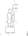
- FIG. 1 illustrates a diagram of an example device 100 that can enable dedicated DCDC conversion for key-off electrical loads in accordance with one or more embodiments of the disclosed subject matter.
- device 100 comprises a battery 110, a main DCDC converter 120, a micro DCDC converter 130, key-off power consumers 150, and non-key-off consumers 140.
- various functions and modules of electric vehicles require power of various voltages.
- the electric motors utilized for propulsion may require a relatively high voltage to operate.
- other functions, such as key-off functions may require power at relatively low voltages such as 12V.
- DCDC converters such as the main DCDC converter 120 and/or micro DCDC converter 130 can convert power from one voltage to another voltage.
- the main DCDC converter 120 is coupled to the battery 110 and to the key-off power consumers 150 and the non-key-off consumers 140.
- the main DCDC converter 120 (and similarly the micro DCDC converter) can convert power supplied by the battery 110 at a first voltage to a second voltage to supply to key-off power consumers 150 and/or non-key-off consumers 140.
- battery 110 can comprise one or more batteries, battery cells, split batteries, and/or battery series and can comprise any physical and/or chemical structure capable of storing and discharging electrical current.
- device 100 can be located within an electric vehicle or a hybrid vehicle. Additionally, battery 110 can be a propulsion or main battery of an electric vehicle.
- a propulsion or main battery can be any battery within an electric vehicle capable of powering one or more electric motors which cause the vehicle to move.
- the battery 110 can be a medium voltage propulsion battery (e.g., 48V) or a high voltage propulsion battery (e.g., 400V or 800V).
- the main DCDC converter 120 can supply power to both the key-off power consumers 150 and the non-key-off consumers 140 from the battery 110.
- an issue occurs when key-off power consumers 150 require power when the electric vehicle is turned off.
- an on-board computer may need to update while the vehicle is turned off in order to not disrupt use of the vehicle.
- existing electric vehicles would either supply power to the key-off power consumers 150 by running the main DCDC converter 120 continuously, or by supplying power to the key-off modules from a separate 12V battery and using the main DCDC converter 120 to charge the 12V battery.
- the first option leads to large amounts of electrical waste, due to the relatively large overhead of operating the main DCDC converter 120, thus decreasing the range of the electric vehicle due to power drain from the battery 110.
- the second option can lead to rapid wear and tear of the 12V battery due to the numerous charge and discharge cycles, leading to increased maintenance time and cost.
- device 100 can solve these issues through the use of micro DCDC converter 130.
- the micro DCDC converter 130 can supply power to the key-off power consumers 150 from the battery.
- the micro DCDC converter 130 is used to supply power only to the key-off power consumers 150 while the vehicle is turned off, the micro DCDC converter 130 does not need to supply the same relatively high amounts of power of the main DCDC converter 120.
- the micro DCDC converter 130 can be designed specifically to convert power from the battery 110 to 12V.
- the micro DCDC converter 130 can be designed to operate with less electrical overhead, and thus operate with less electrical waste when supplying power to the key-off power consumers 150 in comparison to the main DCDC converter 120. Therefore, the micro DCDC converter 130 can increase the range of the electric vehicle by decreasing the power consumption related to the key-off power consumers 150. Additionally, as the micro DCDC converter 130 has a relatively low electrical overhead, in some embodiments, a 12V battery can be eliminated entirely, thus reducing weight and cost of electric vehicles.
- device 100 can also comprise one or more power management computer devices (not shown).
- a power management computer device can control the main DCDC converter 120 and/or the micro DCDC converter 130 based on what modules require power at any given time.
- device 100 can comprise a first power management computer device to operate the main DCDC converter 120 and a second power management computer device to operate the micro DCDC 130.
- FIG. 2 illustrates a diagram of an example device 200 that can enable dedicated DCDC conversion for key-off electrical loads in accordance with one or more embodiments of the disclosed subject matter.
- device 200 comprises a battery 110, a main DCDC converter 120, a micro DCDC converter 130, key-off power consumers 150, and non-key-off consumers 140.
- device 200 comprises high voltage supply system 210, shown as a contactor. When high voltage supply system 210 is active (e.g., the contactor is closed), the main DCDC converter 120 can receive current from the battery 110. However, when the high voltage supply system 210 is inactive (e.g., the contactor is open), then the main DCDC converter 120 cannot receive current from the battery 110.
- the micro DCDC converter 130 can be coupled to the battery 110 before the high voltage supply system 210. Accordingly, the micro DCDC converter can operate when the high voltage supply system is inactive. In this embodiment, device 200 can further ensure power conservation and efficiency. For example, by opening the contactor of high voltage supply system 210, no power can be lost to leakage through the main DCDC converter 120, while the micro DCDC converter 130 can still supply power to the key-off power consumers 150 which may need power. It should be appreciated that through the use of micro DCDC converter 130, devices 100 and or 200 can facilitate reduction of use of or elimination of a 12V battery.
- FIG. 3 illustrates a diagram of an example device 300 that can enable dedicated DCDC conversion for key-off electrical loads in accordance with one or more embodiments of the disclosed subject matter.
- device 300 comprises a battery 110, a main DCDC converter 120, a micro DCDC converter 130, key-off power consumers 150, and non-key-off consumers 140.
- device 300 comprises a 12V battery 310.
- a 12V battery can provide redundancy in supplying power to systems utilizing 12V if the main DCDC converter 120 and/or the micro DCDC converter 130 were to fail.
- the 12V battery 310 can receive power from either the micro DCDC converter 130 or the main DCDC converter 120, depending on which is active.
- FIG. 4 illustrates a diagram of an example device 400 that can enable dedicated DCDC conversion for key-off electrical loads in accordance with one or more embodiments of the disclosed subject matter.
- device 400 comprises a battery 110, a main DCDC converter 120, a micro DCDC converter 130, key-off power consumers 150, and non-key-off consumers 140.
- Device 400 additionally comprises a second micro DCDC converter 410 and as second set of key-off power consumers 420.
- the second micro DCDC converter 410 device 400 can further improve efficiency in supplying power to key-off power consumers 150 and 420. For example, as the number of key-off power consumers increases, the micro DCDC 130 needs to be capable of supplying the power needs of the increased number of key-off power consumers.
- micro DCDC 130 has similar efficiency issues as the main DCDC converter 120 as discussed above. That is, the overhead of operating micro DCDC converter 130 when only a limited number of key-off consumers require power can create the same issues as described above in relation to utilizing a single DCDC. Accordingly, the key-off power consumers can be divided into groupings such as key-off power consumers 150 and the second set of key-off power consumers 420 and a micro DCDC converter, such as micro DCDC converter 130 and second micro DCDC converter 410 can be assigned to each group or set of key-off power consumers. In this embodiment, efficiency and power conservation can be further improved.
- the micro DCDC converter 130 can be active while the second micro DCDC converter 410 is inactive.
- the second micro DCDC converter 410 can be active while the micro DCDC converter 130 is in active.
- device 400 can be scaled to include any number of micro DCDC converters and/or groups of key-off power consumers.
- device 400 can comprise a third micro DCDC coupled to a third group of key-off power consumers, a fourth micro DCDC coupled to a third group of key-off power consumers, etc. Accordingly, if the trend of increasing the number of key-off power consumers in electric vehicles continues, device 400 can be effectively and efficiently scaled accordingly.
- FIG. 5 illustrates a flow diagram of a non-limiting method 500 of manufacture of a device enabling dedicated DCDC conversion for key-off electrical loads in accordance with one or more embodiments of the disclosed subject matter.
- method 500 can comprise coupling a battery (e.g., battery 110) to one or more main conversion units (e.g., main DCDC converter 120).
- the battery can comprise one or more batteries, battery cells, split batteries, and/or battery series and can comprise any physical and/or chemical structure capable of storing and discharging electrical current.
- the battery can be located within an electric vehicle.
- the battery can be a propulsion or main battery of an electric vehicle.
- the battery can be a medium voltage propulsion battery (e.g., 48V) or a high voltage propulsion battery (e.g., 400V or 800V).
- the one or more main converters can also be coupled to one or more key-off modules (e.g., key-off power consumers 150) and/or one or more non-key-off consumers (e.g., non-key-off consumers 140).
- the one or more main conversion units can convert power supplied by the battery in a first voltage to a second voltage.
- method 500 can comprise coupling one or more dedicated key-off conversion units (e.g., micro DCDC converter 130 and/or second micro DCDC converter 410) to the battery (e.g., battery 110).
- the one or more dedicated key-off conversion units can down convert power from the battery to 12V.
- method 500 can comprise coupling one or more key-off electrical modules (e.g., key-off power consumers 150 and/or second grouping of key-off power consumers 420) to the one or more dedicated key-off conversion units (e.g., micro DCDC converter 130 and/or second micro DCDC converter 410).
- key-off electrical modules e.g., key-off power consumers 150 and/or second grouping of key-off power consumers 420
- dedicated key-off conversion units e.g., micro DCDC converter 130 and/or second micro DCDC converter 410.
- FIG. 6 illustrates a flow diagram of a non-limiting method 600 of manufacture of a device enabling dedicated DCDC conversion for key-off electrical loads in accordance with one or more embodiments of the disclosed subject matter.
- method 600 can comprise coupling a battery (e.g., battery 110) to a high voltage module (e.g., high voltage supply system 210).
- the battery can comprise one or more batteries, battery cells, split batteries, and/or battery series and can comprise any physical and/or chemical structure capable of storing and discharging electrical current.
- the battery can be located within an electric vehicle.
- the battery can be a propulsion or main battery of an electric vehicle.
- the battery can be a medium voltage propulsion battery (e.g., 48V) or a high voltage propulsion battery (e.g., 400V or 800V).
- method 600 can comprise coupling one or more main conversion units (e.g., main DCDC converter 120) to the high voltage module (e.g., high voltage supply system 210).
- the one or more main converters can also be coupled to one or more key-off modules (e.g., key-off power consumers 150) and/or one or more non-key-off consumers (e.g., non-key-off consumers 140).
- the one or more main conversion units can convert power supplied by the battery in a first voltage to a second voltage.
- method 600 can comprise coupling one or more dedicated key-off conversion units (e.g., micro DCDC converter 130 and/or second micro DCDC converter 410) to the battery (e.g., battery 110).
- the one or more dedicated key-off conversion units can down convert power from the battery to 12V.
- method 600 can comprise coupling one or more key-off electrical modules (e.g., key-off power consumers 150 and/or second grouping of key-off power consumers 420) to the one or more dedicated key-off conversion units (e.g., micro DCDC converter 130 and/or second micro DCDC converter 410).
- key-off electrical modules e.g., key-off power consumers 150 and/or second grouping of key-off power consumers 420
- dedicated key-off conversion units e.g., micro DCDC converter 130 and/or second micro DCDC converter 410.
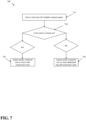
- FIG. 7 illustrates a flow diagram of a non-limiting method 700 of use of a device enabling dedicated DCDC conversion for key-off electrical loads in accordance with one or more embodiments of the disclosed subject matter.
- method 700 can comprise one or more key-off modules requesting power.
- method 700 can comprise determining is the electric vehicle is on or off. If the vehicle is on, the power can be supplied by the one or more main conversion units, as shown at 730. If the vehicle is off, the power can be supplied by the one or more dedicated key-off conversion units, as shown at 740.
- an electric vehicle comprising a device enabling dedicated DCDC conversion for key-off electrical loads, such as devices 100, 200, 300 and 400, has several advantages. For example, by utilizing a dedicated key-off conversion unit when the vehicle is off as opposed to the main conversion unit, the embodiments described herein can conserve battery power as the overhead of operating the dedicated key-off conversion unit is smaller than that of operating the main conversion unit. This can lead to electric vehicles with greater range, as key-off power modules will consume less battery power when the vehicle is off, thereby conserving battery power for driving operations when the vehicle is on. Additionally, one or more embodiments describe above can facilitate the elimination of 12V batteries in electric vehicles, thereby decreasing vehicle weight and manufacture and maintenance costs.
Landscapes
- Engineering & Computer Science (AREA)
- Power Engineering (AREA)
- Mechanical Engineering (AREA)
- Transportation (AREA)
- Life Sciences & Earth Sciences (AREA)
- Sustainable Development (AREA)
- Sustainable Energy (AREA)
- Electric Propulsion And Braking For Vehicles (AREA)
- Charge And Discharge Circuits For Batteries Or The Like (AREA)
Applications Claiming Priority (1)
| Application Number | Priority Date | Filing Date | Title |
|---|---|---|---|
| US17/804,756 US12051970B2 (en) | 2022-05-31 | 2022-05-31 | Dedicated DCDC conversion unit for supplying key-off electrical loads from the propulsion battery in a vehicle |
Publications (1)
| Publication Number | Publication Date |
|---|---|
| EP4286202A1 true EP4286202A1 (de) | 2023-12-06 |
Family
ID=86646566
Family Applications (1)
| Application Number | Title | Priority Date | Filing Date |
|---|---|---|---|
| EP23176315.2A Pending EP4286202A1 (de) | 2022-05-31 | 2023-05-31 | Dedizierte dcdc-umwandlungseinheit zur bereitstellung von schlüsselfreien elektrischen lasten aus der antriebsbatterie in einem fahrzeug |
Country Status (3)
| Country | Link |
|---|---|
| US (1) | US12051970B2 (de) |
| EP (1) | EP4286202A1 (de) |
| CN (1) | CN117141391A (de) |
Cited By (2)
| Publication number | Priority date | Publication date | Assignee | Title |
|---|---|---|---|---|
| EP4585443A1 (de) * | 2024-01-15 | 2025-07-16 | Aptiv Technologies AG | Gleichspannungswandler für fahrzeuge |
| EP4585444A1 (de) * | 2024-01-15 | 2025-07-16 | Aptiv Technologies AG | Gleichspannungswandler für fahrzeuge |
Families Citing this family (3)
| Publication number | Priority date | Publication date | Assignee | Title |
|---|---|---|---|---|
| US12466264B2 (en) * | 2021-03-01 | 2025-11-11 | Volvo Car Corporation | Battery architecture without low voltage battery |
| US11970078B2 (en) * | 2022-09-02 | 2024-04-30 | GM Global Technology Operations LLC | Vehicle accessory load control and power stability |
| DE102024203845B4 (de) * | 2024-04-24 | 2025-12-24 | Schaeffler Technologies AG & Co. KG | Fahrzeugbordnetz und Fahrzeug mit einem derartigen Fahrzeugbordnetz |
Citations (2)
| Publication number | Priority date | Publication date | Assignee | Title |
|---|---|---|---|---|
| US20190275968A1 (en) * | 2018-03-06 | 2019-09-12 | Hyundai Motor Company | Power supply system of vehicle and method of controlling the same |
| US11135928B2 (en) * | 2019-04-12 | 2021-10-05 | Ferrari S.P.A. | Electric system of a road vehicle provided with a DC-DC electronic power converter |
Family Cites Families (13)
| Publication number | Priority date | Publication date | Assignee | Title |
|---|---|---|---|---|
| US6400589B2 (en) * | 2000-01-12 | 2002-06-04 | Toyota Jidosha Kabushiki Kaisha | Control apparatus for a power supply circuit including plural converter |
| KR100906909B1 (ko) | 2006-12-12 | 2009-07-08 | 현대자동차주식회사 | 연료전지 하이브리드 전기 차량의 파워다운 제어방법 |
| GB2452246B (en) | 2007-07-19 | 2012-01-11 | Ford Global Tech Llc | A micro-hybrid motor vehicle |
| US10106038B2 (en) * | 2012-12-28 | 2018-10-23 | Johnson Controls Technology Company | Dual function battery system and method |
| US11070049B2 (en) | 2017-11-08 | 2021-07-20 | Eaton Intelligent Power Limited | System, method, and apparatus for power distribution in an electric mobile application using a combined breaker and relay |
| JP7081958B2 (ja) | 2018-03-30 | 2022-06-07 | 本田技研工業株式会社 | 車両電源システム |
| JP7094780B2 (ja) | 2018-05-31 | 2022-07-04 | 矢崎総業株式会社 | Dc/dc変換ユニット |
| JP2020031471A (ja) * | 2018-08-21 | 2020-02-27 | スズキ株式会社 | 車載電源装置 |
| JP7226356B2 (ja) * | 2020-02-03 | 2023-02-21 | トヨタ自動車株式会社 | 車両用制御装置、方法、プログラム、及び車両 |
| US11021073B1 (en) * | 2020-02-26 | 2021-06-01 | Atieva, Inc. | Electric vehicle power supply system to minimize loss during vehicle rest |
| US11277070B1 (en) | 2020-09-14 | 2022-03-15 | Vitesco Technologies USA, LLC | DC-DC converter with extended light load operating range, and method of using same |
| JP2022049811A (ja) | 2020-09-17 | 2022-03-30 | トヨタ自動車株式会社 | ハイブリッド車両の制御装置 |
| US11708008B2 (en) | 2020-09-29 | 2023-07-25 | GM Global Technology Operations LLC | Electric powertrain with multi-pack battery system and mutually-exclusive 3-way contactor |
-
2022
- 2022-05-31 US US17/804,756 patent/US12051970B2/en active Active
-
2023
- 2023-05-31 EP EP23176315.2A patent/EP4286202A1/de active Pending
- 2023-05-31 CN CN202310636121.4A patent/CN117141391A/zh active Pending
Patent Citations (2)
| Publication number | Priority date | Publication date | Assignee | Title |
|---|---|---|---|---|
| US20190275968A1 (en) * | 2018-03-06 | 2019-09-12 | Hyundai Motor Company | Power supply system of vehicle and method of controlling the same |
| US11135928B2 (en) * | 2019-04-12 | 2021-10-05 | Ferrari S.P.A. | Electric system of a road vehicle provided with a DC-DC electronic power converter |
Cited By (2)
| Publication number | Priority date | Publication date | Assignee | Title |
|---|---|---|---|---|
| EP4585443A1 (de) * | 2024-01-15 | 2025-07-16 | Aptiv Technologies AG | Gleichspannungswandler für fahrzeuge |
| EP4585444A1 (de) * | 2024-01-15 | 2025-07-16 | Aptiv Technologies AG | Gleichspannungswandler für fahrzeuge |
Also Published As
| Publication number | Publication date |
|---|---|
| US20230387795A1 (en) | 2023-11-30 |
| US12051970B2 (en) | 2024-07-30 |
| CN117141391A (zh) | 2023-12-01 |
Similar Documents
| Publication | Publication Date | Title |
|---|---|---|
| EP4286202A1 (de) | Dedizierte dcdc-umwandlungseinheit zur bereitstellung von schlüsselfreien elektrischen lasten aus der antriebsbatterie in einem fahrzeug | |
| CN109080560B (zh) | 一种纯电动汽车dcdc控制系统及控制方法 | |
| US8193761B1 (en) | Hybrid power source | |
| CN108340856A (zh) | 一种取消低压电池的新能源汽车供电系统 | |
| EP3078536A1 (de) | Energiespeichersystem mit reichweitenerweiterer und energieverwaltungs- und -steuerungsverfahren | |
| CN104139708A (zh) | 一种电动汽车用动力控制供电系统 | |
| JP7006572B2 (ja) | 車両用充電制御システム | |
| CN109969000B (zh) | 一种纯电动车用增程式系统 | |
| CN114394083B (zh) | 混合动力汽车扭矩分配方法和系统 | |
| KR20210029424A (ko) | 차량의 다중 전원 분배 제어 시스템 및 분배 제어 방법 | |
| CN110293845A (zh) | 启停电池系统、启停电池控制方法和交通载具 | |
| Jinrui et al. | Simulation and analysis of performance of a pure electric vehicle with a super-capacitor | |
| CN113428335A (zh) | 一种改进的船用燃料电池顶推船-驳船混合动力系统及其控制方法 | |
| CN113428334A (zh) | 一种船用燃料电池顶推船-驳船混合动力系统及其控制方法 | |
| CN203739810U (zh) | 车辆控制器的电源供电装置和应用其的车辆控制系统 | |
| CN114506246B (zh) | 一种电动汽车动力电池换电系统的分时控制方法 | |
| CN111422067A (zh) | 用于双电池管理系统的上下电互切控制系统及电动商务车 | |
| KR100911537B1 (ko) | 고전압 배터리의 충전제어장치 | |
| CN210852065U (zh) | 一种电动汽车及其车载供电装置 | |
| CN109050255A (zh) | 一种电动客车智能断低压电装置 | |
| CN112740499B (zh) | 电动车辆的控制方法和电动车辆系统 | |
| CN201325339Y (zh) | 一种用于船舶电力推进系统的供电系统 | |
| JP2007022210A (ja) | 車両用電源装置 | |
| CN106080219A (zh) | 锂电池电动巡逻车 | |
| CN119975010B (zh) | 一种新能源车智能补电系统及方法 |
Legal Events
| Date | Code | Title | Description |
|---|---|---|---|
| PUAI | Public reference made under article 153(3) epc to a published international application that has entered the european phase |
Free format text: ORIGINAL CODE: 0009012 |
|
| STAA | Information on the status of an ep patent application or granted ep patent |
Free format text: STATUS: THE APPLICATION HAS BEEN PUBLISHED |
|
| AK | Designated contracting states |
Kind code of ref document: A1 Designated state(s): AL AT BE BG CH CY CZ DE DK EE ES FI FR GB GR HR HU IE IS IT LI LT LU LV MC ME MK MT NL NO PL PT RO RS SE SI SK SM TR |
|
| STAA | Information on the status of an ep patent application or granted ep patent |
Free format text: STATUS: REQUEST FOR EXAMINATION WAS MADE |
|
| 17P | Request for examination filed |
Effective date: 20240605 |
|
| RBV | Designated contracting states (corrected) |
Designated state(s): AL AT BE BG CH CY CZ DE DK EE ES FI FR GB GR HR HU IE IS IT LI LT LU LV MC ME MK MT NL NO PL PT RO RS SE SI SK SM TR |