EP4286236A1 - Système de marchepied pour un véhicule - Google Patents
Système de marchepied pour un véhicule Download PDFInfo
- Publication number
- EP4286236A1 EP4286236A1 EP23172030.1A EP23172030A EP4286236A1 EP 4286236 A1 EP4286236 A1 EP 4286236A1 EP 23172030 A EP23172030 A EP 23172030A EP 4286236 A1 EP4286236 A1 EP 4286236A1
- Authority
- EP
- European Patent Office
- Prior art keywords
- tread
- profile
- elements
- brush
- row
- Prior art date
- Legal status (The legal status is an assumption and is not a legal conclusion. Google has not performed a legal analysis and makes no representation as to the accuracy of the status listed.)
- Pending
Links
Images

Classifications
-
- B—PERFORMING OPERATIONS; TRANSPORTING
- B60—VEHICLES IN GENERAL
- B60R—VEHICLES, VEHICLE FITTINGS, OR VEHICLE PARTS, NOT OTHERWISE PROVIDED FOR
- B60R3/00—Arrangements of steps or ladders facilitating access to or on the vehicle, e.g. running-boards
- B60R3/02—Retractable steps or ladders, e.g. movable under shock
-
- B—PERFORMING OPERATIONS; TRANSPORTING
- B61—RAILWAYS
- B61D—BODY DETAILS OR KINDS OF RAILWAY VEHICLES
- B61D23/00—Construction of steps for railway vehicles
Definitions
- the present invention relates to a step system for a vehicle, comprising a step plate which is movable below a step bar edge of the vehicle along an extension axis extending perpendicular to the step bar edge from an insertion position in the direction of an extension position and vice versa, the step plate having a step-loadable tread surface has, on which an anti-slip profile is formed, the anti-slip profile having a plurality of profile elements, each profile element being raised in relation to a tread base and having a greater length along a respective profile element longitudinal axis than along a profile element transverse axis running perpendicular to the longitudinal axis of the profile element and parallel to the base of the tread surface.
- Step systems with step plates that can be moved between an insertion position and an extension position are used in particular in vehicles for transporting people, e.g. B. in the area of public transport.
- vehicles for transporting people
- road vehicles e.g. buses
- rail vehicles e.g. trams, subways, trams, local and long-distance trains, high-speed trains, etc.
- Step systems are generally used to make it easier to get in and out of a vehicle, i.e. they serve as an aid to getting in and out.
- a stopping platform for example a train platform or bus platform
- the vehicle is in a rest position so that passengers can enter or exit the vehicle.
- step systems that are extended or folded out in the direction of the platform when the vehicle is at rest represent a possibility to reduce the gap size between the vehicle and the platform or platform to reduce.
- Such a step system can, for example, be designed as a step plate and absorbs the weight of the passengers when passengers get on or off, i.e. it is subjected to a step load
- a step system (including a movable step plate) can make it easier to get in and out of the vehicle. Even if the vehicle stops on a level surface, a step system can at least be used to overcome a height difference between the level surface and the floor of the passenger compartment; this applies even more to passengers with physical disabilities, such as wheelchair users.
- the tread plate of the tread system serves as a ramp.
- the pedaling system In order to ensure sufficient surefootedness for passengers boarding or alighting, as well as to enable the pedaling system to have the longest possible service life during continuous use, it is necessary that the pedaling system has sufficient mechanical stability.
- Tread systems with tread plates or tread surfaces made of metal are particularly suitable for this purpose.
- the treads can be provided with structures or mats that have an anti-slip effect and reduce the risk of slipping for the passenger when getting in and out.
- corrugated sheets are often used to create an anti-slip profile.
- An anti-slip profile is formed on a sheet metal surface (which also provides a tread surface), namely in the form of a plurality of profile elements, each of which is raised in relation to a tread base (of the sheet metal) and forms a corrugated pattern.
- the corrugation (provided by the profile elements) is created during the production of the sheet metal by forming rolling.
- Known corrugation patterns formed by the profile elements are, for example, duet patterns or quintet patterns, each of which is composed of a large number of structural units, the structural units each comprising two or five parallel-aligned profile elements.
- the profile elements of neighboring structural units are directed in different directions, so that there is an overall corrugated pattern without directionality results.
- the corrugated patterns also provide an anti-slip effect, when using such corrugated plates as tread plates in tread systems, it was found that the corrugated plates can often only be cleaned or swept away inadequately. Dirt particles released by passengers onto the corrugated plates (e.g. in the form of dust, stones, earth or grit) remain between the profile elements of the corrugated structures (even after cleaning or sweeping). Accordingly, there is a need for improved systems in this regard.
- the present invention is therefore based on the object of providing a tread system whose tread plate can be cleaned in a simplified manner and with improved efficiency.
- the invention relates to a step system for a vehicle, comprising a step plate which is movable below a step strip edge of the vehicle along an extension axis extending perpendicular to the step strip edge from an insertion position towards an extension position and vice versa, the step plate having a tread-loadable tread surface has an anti-slip surface Profile is formed, wherein the anti-slip profile has a plurality of profile elements, each profile element being raised in relation to a tread base and having a greater length along a respective profile element longitudinal axis than along a perpendicular to the profile element longitudinal axis and parallel Profile element transverse axis running to the base of the tread.
- the step system is characterized in that the profile elements are arranged in rows.
- the mentioned step strip edge is arranged between the floor level of a vehicle interior and a cavity (e.g. push-out box) for receiving the step plate.
- the step strip edge can, for example, be part of the vehicle outer skin or a slide-out box.
- the tread plate is arranged below a lower edge of the tread strip edge.
- the movement of the step plate (which is preferably designed as a sliding step) from an insertion position towards an extension position and vice versa is provided via a suitable drive device, which should not be further specified at this point.
- the tread plate can be designed to be lowerable (pivoting) in order to provide a ramp function.
- the tread surface is designed to be tread-resistant, which means that the tread plate can absorb the weight exerted by passengers on the tread plate when getting in and out.
- An “anti-slip profile” means that the risk of a passenger slipping when getting on or off is reduced compared to a smooth surface.
- Metallic surfaces in particular can be smooth (without appropriate profiling) and cause an increased risk of slipping. This effect is further increased when it is wet, which is why anti-slip profiles are almost essential for tread plates. Because of the constant contact with passengers' shoes, both dirt and moisture are released onto the footplate. In the extended position, precipitation such as rain, snow, hail or the like can also deposit directly on the tread plate, which can further increase the risk of slipping. The anti-slip profile counteracts this.
- the profile elements are raised in relation to the tread base. This means that the profile elements protrude or protrude upwards in relation to a surface formed by the tread base. In other words, those profile element surfaces associated with the profile elements have a different (higher) vertical level in the vertical direction than the base of the tread surface.
- a respective profile element has a greater length along its respective profile element longitudinal axis than in a profile element transverse axis running perpendicular to the profile element longitudinal axis and parallel to the tread base.
- the profile elements have a greater length than width.
- the profile elements also have a greater length than height (based on a height starting from the base of the tread).
- Arranging the profile elements in rows provides a directional arrangement, which facilitates the cleaning/removal of dirt particles (e.g. in the form of dust, stones, earth or grit) deposited in the spaces between the profile elements. If, for example, such a tread plate is swept away along the alignment of the profile elements (i.e. cleaned in a direction-specific manner), dirt particles can be removed more easily than with the checker plates known from the prior art.
- dirt particles e.g. in the form of dust, stones, earth or grit
- each row has a row axis along which a plurality of profile elements are arranged in alignment one behind the other.
- the profile elements can thus be lined up one behind the other in a respective row.
- the respective profile element longitudinal axes preferably extend in the direction (ie parallel) to the row axis.
- the rows of profile elements arranged one behind the other can extend over the entire length of the tread plate in a direction along the extension axis. This means that profile elements are arranged or lined up one behind the other in a respective row from a rear end of the tread plate to a front end of the tread plate.
- the profile elements of rows arranged next to one another are arranged at a row distance from one another.
- the row spacing can be the same for all adjacent rows of profile elements.
- the row spacing can be, for example, in the range from 1 mm to 20 mm, in particular 1 mm, 5 mm, 10 mm or 20 mm.
- the row spacing can also take on other values.
- dirt particles of different sizes e.g. grain size
- the row spacing can vary.
- the profile elements arranged in alignment one behind the other in a respective row are arranged at a distance from one another or directly adjacent to one another.
- a rear end of the front profile element can directly adjoin a front end of the rear profile element (i.e. be in material contact). If profile elements are arranged at a distance from one another, there is no material contact between the profile elements.
- the profile elements each have a tread-loadable profile element tread surface, the majority of the profile elements with their respective profile element tread surfaces spanning a profile element tread surface plane parallel to the base of the tread surface.
- the profile elements are preferably arranged in such a way that when a passenger steps on the tread plate, they are at least partially and temporarily contacted by the passenger's shoe sole and thus at least partially as Serve as a stepping surface.
- the profile elements thus form with their respective profile element tread surfaces an overall profile element tread surface, the profile element tread surface level of which is arranged above the base of the tread surface.
- both the tread plate base and part of the profile element tread surfaces can be in contact with the shoe sole, so that parts of a shoe sole rest on the tread plate base and parts of the shoe sole rest on the profile element tread surfaces, which creates an anti-slip effect.
- the anti-slip effect mentioned can be due to increased friction between the shoe sole and the profiled tread surface or due to partial positive fit between the profile elements and the shoe sole.
- the profile elements of the tread plate give a profile that reduces the risk of a passenger slipping or slipping.
- the anti-slip effect is particularly effective because, on the one hand, the water that comes into contact with the tread plate can flow away via the base of the tread plate, but on the other hand, the water tends to collect on the base of the tread plate rather than on a surface of the profile elements, which is why the profile elements are even when wet provide sufficient slip resistance. Water that has accumulated on the profile element surfaces can also be displaced towards the base of the tread when it comes into contact with a shoe sole.
- the profile element tread surface of a respective profile element has an oval shape, a rectangular shape, an ellipse shape or a pointed ellipse shape.
- An at least partially rounded profile shape such as an oval shape, ellipse shape or the shape of a pointed ellipse can be advantageous when cleaning or when sweeping away the tread plate, since brushes or bristles guided over the tread plate slide along the rounded profile elements. Even with a rectangular shape, brushes or bristles can slide along a rectangular edge, but the risk of getting caught or wedged when the brushes or bristles slide past - in the transition area between two rectangular profile elements - is increased.
- an at least partially rounded profile shape such as an oval shape, elliptical shape or the shape of a pointed ellipse is particularly gentle on the material of the bristle brushes, which increases their service life.
- the profile elements can already be used during production Tread plate can be formed or formed in the desired shape directly from the tread plate material.
- profile elements arranged in mutually adjacent rows are arranged longitudinally offset.
- the longitudinal offset refers to a direction along the extension axis, i.e. H. the profile elements in adjacent rows are not arranged directly next to one another (i.e. not arranged in parallel at the same height or in the same row position). This can further increase the anti-slip effect.
- adjacent rows comprise a different number of profile elements. This also allows a longitudinal offset to be achieved and the anti-slip effect to be improved. With respect to a front edge of the tread plate, adjacent profile element rows do not end at the same height if there is a longitudinal offset.
- every second row can have the same arrangement or number of profile elements.
- a row after the next in relation to a row comprises the same number of profile elements.
- every second row can include the same number of profile elements.
- the row axes extend parallel to the extension axis.
- the profile element longitudinal axes also extend parallel to the extension axis.
- a brush structure is arranged on the edge of the tread strip, which has brush elements which are designed to clean the tread surface of the tread plate when the tread plate is moved along the extension axis.
- An extension of the row axes (or profile element longitudinal axes) parallel to the extension axis is advantageous for an efficient cleaning effect. This is because contamination or dirt particles in the spaces between adjacent rows can be effectively swept away by the brush elements.
- part of the brush elements can slide or be guided along the spaces arranged between the rows.
- the brush structure can include brush elements that slide or are guided over the surfaces of the profile elements and thus also clean them.
- the brush elements therefore do not have to be actively moved to clean the tread plate; rather, they remain in a fixed position.
- provision can also be made to move the brush structure as a whole relative to the tread plate, for example in the opposite direction to the direction of movement of the tread plate.
- a movement of the brush structure directed transversely to the extension axis of the tread plate can alternatively or additionally be provided.
- individual brush elements can be moved in opposite directions or transversely to the direction of movement of the tread plate. If a movement of the brush structure or individual brush elements is desired, these are movably mounted and driven according to the desired movement. It is also conceivable to mount individual brush elements (or all brush elements) in a non-driven, but movable manner, for example via ball joints assigned to the respective brush elements.
- the brush structure has first brush elements and second brush elements, the first brush elements having a first length in the direction of the tread plate, and the second brush elements having a second length in the direction of the tread plate , where the first and second lengths differ from each other.
- the first brush elements are designed to contact the base of the tread surface when moving the tread plate along the extension axis
- the second brush elements are designed to contact the tread surface base when moving along the tread plate the extension axis to contact the profile element tread surfaces.
- Those brush elements provided for contacting the base of the tread surface advantageously have a greater length than those second brush elements provided for contacting the profile element tread surfaces (or profile element surfaces).
- the first brush elements can thus sweep away the tread surface base while the second brush elements sweep away the profile element tread surfaces.
- first brush elements and the second brush elements do not directly contact the respective tread bases or profile element tread surfaces, but are arranged with their lower ends at a small distance therefrom. Even then, those particles that have a size that exceeds the specified distance can be removed.
- the first and second brush elements are each arranged in brush element rows extending perpendicular to the extension axis, with the first brush elements in a first brush element row and the second brush elements in a second Brush element row are arranged.
- the first row of brush elements and the second row of brush elements can be arranged one behind the other, wherein in a first variant the first row of brush elements can provide a front row towards the outside of the vehicle and the second row of brush elements can provide a rear row towards the outside of the vehicle.
- the second row of brush elements can provide a front row towards the outside of the vehicle and the first row of brush elements can provide a rear row towards the outside of the vehicle.
- first brush elements and second brush elements are arranged together in one or more rows of brush elements extending perpendicular to the extension axis, with the first and second brush elements being arranged in a respective brush element -Row are arranged alternately.
- every second brush element can be a first or second brush element.
- the first brush elements and the second brush elements are designed in the form of bristles.
- the bristles can be made of a synthetic or natural material. Natural materials can be plant or animal in nature. Coconut and Arenga bristles are examples of natural bristle materials. Animal-based bristles can be made from horsehair, for example. Synthetically manufactured bristles can be made, for example, from PVC, polypropylene, polyester, polyamide or similar materials. Combinations of plant and synthetic materials can also be used to produce bristles. The bristles can therefore be single-component or multi-component bristles.
- the bristles can be made from composite materials. The bristles can also be made entirely or partially from natural or synthetically produced rubber.
- the first brush elements have a bristle diameter that is less than or equal to the row spacing of profile elements arranged next to one another. The spaces between the rows of profile elements can then be guided along and cleaned along the respective first brush elements when the tread plate is moved. If the first brush elements have a bristle diameter that is smaller than the specified row spacing, then - depending on the bristle diameter - several of the first brush elements can be positioned within a gap arranged between two rows and can be guided along the gap when the tread plate is moved.
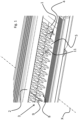
- Fig. 1 is a step system for a vehicle (the vehicle is not shown), comprising a step plate 1, which is below a step strip edge 2 of the vehicle along an extension axis X extending perpendicular to the step strip edge 2 from an insertion position towards an extension position and vice versa is movable.
- the tread plate 1 has a tread-loadable tread surface 3 on which an anti-slip profile is formed, the anti-slip profile having a plurality of profile elements 4.
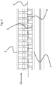
- Each profile element 4 is raised in relation to a tread base 5 and has a greater length along a respective profile element longitudinal axis 6 than along a profile element transverse axis 7 (this one) running perpendicular to the profile element longitudinal axis 6 and parallel to the tread base 5 Connection is in Fig. 3 shown in detail).
- the profile elements 4 are arranged in rows 8.
- Each row 8 has a row axis 9, along which a plurality of profile elements 4 are arranged in alignment one behind the other.
- the row axes 9 extend parallel to the extension axis X.
- the profile elements 4 of rows 8 arranged next to one another are arranged at a row distance from one another.
- the row spacing is defined as the smallest distance between the profile elements 4 of two adjacent rows 8 in a direction perpendicular to the extension axis adjacent rows 8 of profile elements 4 present gap 10.
- they are aligned one behind the other in a respective row 8 arranged profile elements 4 arranged at a distance from one another (cf. Fig. 1 , 3 ).
- the profile elements 4 can also be arranged directly adjacent to one another.
- the profile elements 4 each have a treadable profile element tread surface 11 in the form of a pointed ellipse. Furthermore, the profile elements 4 with their respective profile element tread surfaces 11 span a profile element tread surface E that is parallel to the tread surface base 5 ( Fig. 3 , 4 ). Profile elements 4 arranged in mutually adjacent rows 8 are arranged longitudinally offset.
- a brush structure 12 is arranged on the tread strip edge 2, which has brush elements 13, 14, which are designed to clean the tread surface 3 of the tread plate 1 when the tread plate 1 is moved along the extension axis X.
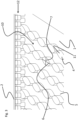
- the brush structure 12 has first brush elements 13 and second brush elements 14, wherein the first brush elements 13 have a first length in the direction of the tread plate 1, and wherein the second brush elements 14 have a second length in the direction of the tread plate 1, the first and second lengths differ from each other.
- the first brush elements 13 can be designed to contact the tread surface base 5 when moving the tread plate 1 along the extension axis X (i.e. to grind or sweep over the tread surface base 5 in a cleaning manner).
- the second brush elements 14 can be designed to contact the profile element tread surfaces 11 when moving the tread plate 1 along the extension axis X (i.e. to grind or sweep over the profile element tread surfaces 11).
- the first brush elements 13 can be designed and arranged in such a way that their lower ends are arranged at a short distance from the tread base 5, ie do not rub over the tread base 5.
- the same can apply to the second brush elements 14 in relation to the profile element tread surfaces 11, that is, the second brush elements 14 can be arranged with their respective lower ends at a small distance from the profile element tread surfaces 11, that is, they cannot grind over the profile element tread surfaces 11 . If particles to be removed (dirt particles, stones, grit) are larger than the distance mentioned, these particles can still be removed and taken away by the brush elements 13, 14.
- the first and second brush elements 13, 14 are each arranged in brush element rows extending perpendicular to the extension axis (here front) are arranged.
- the first brush elements 13 and 14 are arranged offset perpendicular to the extension axis X with respect to the associated direction of extension of the brush structure 12. This means that the first and second brush elements 13, 14 arranged in the respective brush element rows are not arranged directly one behind the other, but rather slightly offset, for example by half the diameter (or half the bristle diameter) of the brush elements 13, 14.
- the first brush elements 13 and the second brush elements 14 are designed in the form of bristles (cf. Fig. 2 to 4 ).
- the first brush elements 13 have a bristle diameter that is less than or equal to the row spacing of profile elements 4 arranged next to one another. So one or more (cf. Fig. 3 , 4 ) first brush elements clean or sweep the space 10 between the profile elements 4.
Landscapes
- Engineering & Computer Science (AREA)
- Mechanical Engineering (AREA)
- Road Paving Structures (AREA)
- Brushes (AREA)
- Vehicle Step Arrangements And Article Storage (AREA)
Applications Claiming Priority (1)
| Application Number | Priority Date | Filing Date | Title |
|---|---|---|---|
| DE202022103042.1U DE202022103042U1 (de) | 2022-05-30 | 2022-05-30 | Trittsystem für ein Fahrzeug |
Publications (1)
| Publication Number | Publication Date |
|---|---|
| EP4286236A1 true EP4286236A1 (fr) | 2023-12-06 |
Family
ID=86330652
Family Applications (1)
| Application Number | Title | Priority Date | Filing Date |
|---|---|---|---|
| EP23172030.1A Pending EP4286236A1 (fr) | 2022-05-30 | 2023-05-08 | Système de marchepied pour un véhicule |
Country Status (3)
| Country | Link |
|---|---|
| US (1) | US12522144B2 (fr) |
| EP (1) | EP4286236A1 (fr) |
| DE (1) | DE202022103042U1 (fr) |
Citations (7)
| Publication number | Priority date | Publication date | Assignee | Title |
|---|---|---|---|---|
| CN105799600A (zh) * | 2016-03-11 | 2016-07-27 | 河南科技大学 | 用于伸缩踏板组件的导向装置及伸缩踏板组件、车辆 |
| EP3130518A1 (fr) * | 2015-08-14 | 2017-02-15 | ALSTOM Transport Technologies | Marchepied de vehicule sur rails dote d'une protection contre le givre |
| DE102015122174A1 (de) * | 2015-12-18 | 2017-06-22 | Bombardier Transportation Gmbh | Trittstufeneinrichtung für ein Fahrzeug zur Personenbeförderung, insbesondere Schienenfahrzeug und entsprechendes Fahrzeug |
| CN209208767U (zh) * | 2018-11-20 | 2019-08-06 | 北京启联恒通轨道交通科技有限公司 | 一种列车踏板系统 |
| WO2020020559A1 (fr) * | 2018-07-24 | 2020-01-30 | Siemens Mobility Austria Gmbh | Comble-lacune pour véhicule ferroviaire |
| CN211107418U (zh) * | 2019-10-24 | 2020-07-28 | 乐清市明实车辆配件有限公司 | 一种铁路货车用防滑脚踏板 |
| CN212195444U (zh) * | 2020-04-13 | 2020-12-22 | 北京启联恒通轨道交通科技有限公司 | 一种列车间隙补偿踏板系统 |
Family Cites Families (14)
| Publication number | Priority date | Publication date | Assignee | Title |
|---|---|---|---|---|
| US2156777A (en) * | 1936-07-11 | 1939-05-02 | Otho C Duryea | Safety tread |
| US3627502A (en) * | 1968-10-01 | 1971-12-14 | Nat Steel Corp | Tread plate and manufacture |
| DE19917022C2 (de) | 1999-04-15 | 2001-05-03 | Michael Wirth | Heckeinstiegauftritt für ein Straßentransportfahrzeug |
| US20020018908A1 (en) | 1999-11-19 | 2002-02-14 | Smith Troy G. | Structures having enhanced slip-resistant surfaces and associated methods |
| KR20050120608A (ko) * | 2005-12-06 | 2005-12-22 | 성원강업 주식회사 | 비계용 작업발판 |
| DE102008061852C5 (de) | 2008-12-15 | 2018-01-04 | Bombardier Transportation Gmbh | Schiebetrittanordnung für ein Schienenfahrzeug |
| CN202783218U (zh) | 2012-09-18 | 2013-03-13 | 吴正良 | 列车车厢与站台安全连接跳板 |
| KR101487403B1 (ko) * | 2013-06-10 | 2015-01-29 | (주)진합 | 차량용 가동 발판 장치 |
| CN108974028A (zh) * | 2016-03-11 | 2018-12-11 | 河南科技大学 | 一种用于伸缩踏板组件的导向装置及伸缩踏板组件、车辆 |
| US10011231B1 (en) * | 2017-10-27 | 2018-07-03 | Iddea California, Llc | Side step for motor vehicle |
| JP7066598B2 (ja) | 2018-11-26 | 2022-05-13 | トヨタ車体株式会社 | 車両用ステップ構造 |
| DE102020208696A1 (de) * | 2020-07-13 | 2022-01-13 | Siemens Mobility GmbH | Schienenfahrzeug mit ausfahrbarer Trittplattform |
| US12252096B2 (en) * | 2021-07-06 | 2025-03-18 | N-Fab, Inc. | Vehicle step assembly |
| CN113715738B (zh) * | 2021-09-22 | 2023-03-17 | 东风越野车有限公司 | 一种多功能电动上车踏板系统及其控制方法 |
-
2022
- 2022-05-30 DE DE202022103042.1U patent/DE202022103042U1/de active Active
-
2023
- 2023-05-08 EP EP23172030.1A patent/EP4286236A1/fr active Pending
- 2023-05-19 US US18/320,572 patent/US12522144B2/en active Active
Patent Citations (7)
| Publication number | Priority date | Publication date | Assignee | Title |
|---|---|---|---|---|
| EP3130518A1 (fr) * | 2015-08-14 | 2017-02-15 | ALSTOM Transport Technologies | Marchepied de vehicule sur rails dote d'une protection contre le givre |
| DE102015122174A1 (de) * | 2015-12-18 | 2017-06-22 | Bombardier Transportation Gmbh | Trittstufeneinrichtung für ein Fahrzeug zur Personenbeförderung, insbesondere Schienenfahrzeug und entsprechendes Fahrzeug |
| CN105799600A (zh) * | 2016-03-11 | 2016-07-27 | 河南科技大学 | 用于伸缩踏板组件的导向装置及伸缩踏板组件、车辆 |
| WO2020020559A1 (fr) * | 2018-07-24 | 2020-01-30 | Siemens Mobility Austria Gmbh | Comble-lacune pour véhicule ferroviaire |
| CN209208767U (zh) * | 2018-11-20 | 2019-08-06 | 北京启联恒通轨道交通科技有限公司 | 一种列车踏板系统 |
| CN211107418U (zh) * | 2019-10-24 | 2020-07-28 | 乐清市明实车辆配件有限公司 | 一种铁路货车用防滑脚踏板 |
| CN212195444U (zh) * | 2020-04-13 | 2020-12-22 | 北京启联恒通轨道交通科技有限公司 | 一种列车间隙补偿踏板系统 |
Also Published As
| Publication number | Publication date |
|---|---|
| US12522144B2 (en) | 2026-01-13 |
| US20230382307A1 (en) | 2023-11-30 |
| DE202022103042U1 (de) | 2023-09-04 |
Similar Documents
| Publication | Publication Date | Title |
|---|---|---|
| DE2933363C2 (fr) | ||
| DE19612133A1 (de) | Wischblatt für eine Fahrzeugscheibenwischervorrichtung | |
| WO2011069701A1 (fr) | Profil de bande de roulement de pneumatique de véhicule | |
| DE60009292T2 (de) | Vorrichtung und verfahren zur bodenbelüftung mit abfallsammlung | |
| DE102008030810A1 (de) | Fahrzeugluftreifen | |
| EP2240066B1 (fr) | Dispositif de nettoyage | |
| DE10007808B4 (de) | Wischblatt | |
| DE202022103042U1 (de) | Trittsystem für ein Fahrzeug | |
| DE202020103509U1 (de) | Vorrichtung zum Reinigen von Reifenlaufflächen | |
| DE69409628T2 (de) | Bürstenrolle für automatische Kraftfahrzeug-Waschanlage | |
| EP1035903B1 (fr) | Installation de filtrage | |
| EP1091903B1 (fr) | Guidage de main courante d'un escalier roulant ou d'un trottoir roulant | |
| DE102015122174B4 (de) | Trittstufeneinrichtung für ein Fahrzeug zur Personenbeförderung, insbesondere Schienenfahrzeug und entsprechendes Fahrzeug | |
| DE4015871A1 (de) | Vorrichtung zur verminderung von windgeraeuschen an fahrzeugen, insbesondere an der fahrzeugunterseite | |
| DE102017214877A1 (de) | Fahrzeugluftreifen | |
| DE4406093C2 (de) | Fußmatte | |
| DE102020120183A1 (de) | Schienenfahrzeug mit Schienenräumer | |
| DE102019101292A1 (de) | Luftleitvorrichtung und Kraftfahrzeug | |
| EP0955005B1 (fr) | Paillasson | |
| DE19543164A1 (de) | Vorrichtung zum Reinigen von Oberflächen | |
| EP1059214A2 (fr) | Dispositif de transport | |
| AT403560B (de) | Fahrzeugluftreifen mit einem profilierten laufstreifen | |
| DE3103290C2 (de) | "Fußraummatte aus Gummi, Kunststoff o.dgl. für Kraftfahrzeuge" | |
| DE102015207326A1 (de) | Spoilerlippe für ein Kraftfahrzeug | |
| DE202014106066U1 (de) | Saugdüse für einen Staubsauger |
Legal Events
| Date | Code | Title | Description |
|---|---|---|---|
| PUAI | Public reference made under article 153(3) epc to a published international application that has entered the european phase |
Free format text: ORIGINAL CODE: 0009012 |
|
| STAA | Information on the status of an ep patent application or granted ep patent |
Free format text: STATUS: THE APPLICATION HAS BEEN PUBLISHED |
|
| AK | Designated contracting states |
Kind code of ref document: A1 Designated state(s): AL AT BE BG CH CY CZ DE DK EE ES FI FR GB GR HR HU IE IS IT LI LT LU LV MC ME MK MT NL NO PL PT RO RS SE SI SK SM TR |
|
| STAA | Information on the status of an ep patent application or granted ep patent |
Free format text: STATUS: REQUEST FOR EXAMINATION WAS MADE |
|
| 17P | Request for examination filed |
Effective date: 20240429 |
|
| RBV | Designated contracting states (corrected) |
Designated state(s): AL AT BE BG CH CY CZ DE DK EE ES FI FR GB GR HR HU IE IS IT LI LT LU LV MC ME MK MT NL NO PL PT RO RS SE SI SK SM TR |
|
| STAA | Information on the status of an ep patent application or granted ep patent |
Free format text: STATUS: EXAMINATION IS IN PROGRESS |
|
| 17Q | First examination report despatched |
Effective date: 20250711 |
|
| GRAP | Despatch of communication of intention to grant a patent |
Free format text: ORIGINAL CODE: EPIDOSNIGR1 |
|
| STAA | Information on the status of an ep patent application or granted ep patent |
Free format text: STATUS: GRANT OF PATENT IS INTENDED |
|
| INTG | Intention to grant announced |
Effective date: 20260714 |