EP2240066B1 - Dispositif de nettoyage - Google Patents
Dispositif de nettoyage Download PDFInfo
- Publication number
- EP2240066B1 EP2240066B1 EP09703752A EP09703752A EP2240066B1 EP 2240066 B1 EP2240066 B1 EP 2240066B1 EP 09703752 A EP09703752 A EP 09703752A EP 09703752 A EP09703752 A EP 09703752A EP 2240066 B1 EP2240066 B1 EP 2240066B1
- Authority
- EP
- European Patent Office
- Prior art keywords
- cleaning device
- bristles
- supporting plane
- brush
- bristle
- Prior art date
- Legal status (The legal status is an assumption and is not a legal conclusion. Google has not performed a legal analysis and makes no representation as to the accuracy of the status listed.)
- Active
Links
Images


Classifications
-
- A—HUMAN NECESSITIES
- A47—FURNITURE; DOMESTIC ARTICLES OR APPLIANCES; COFFEE MILLS; SPICE MILLS; SUCTION CLEANERS IN GENERAL
- A47L—DOMESTIC WASHING OR CLEANING; SUCTION CLEANERS IN GENERAL
- A47L23/00—Cleaning footwear
- A47L23/22—Devices or implements resting on the floor for removing mud, dirt, or dust from footwear
- A47L23/26—Mats or gratings combined with brushes ; Mats
-
- B—PERFORMING OPERATIONS; TRANSPORTING
- B60—VEHICLES IN GENERAL
- B60S—SERVICING, CLEANING, REPAIRING, SUPPORTING, LIFTING, OR MANOEUVRING OF VEHICLES, NOT OTHERWISE PROVIDED FOR
- B60S3/00—Vehicle cleaning apparatus not integral with vehicles
- B60S3/04—Vehicle cleaning apparatus not integral with vehicles for exteriors of land vehicles
- B60S3/042—Wheel cleaning devices
Definitions
- the invention relates to a cleaning device for soiled and / or contaminated surfaces, in particular for running surfaces of shoes or tires of vehicles, wherein the cleaning device comprises a brush device comprising bristle carrier and bristles brushes for cleaning treatment of the running surfaces and a support device for supporting the running surfaces in one Supporting plane, wherein the brushes are arranged in a receiving space, the support level limits a working space for the running surfaces and the bristles each extend with a free end of the receiving space into the working space.
- the bristles close in a rest position with the support plane an angle greater than 0 ° and less than 90 °, pass through the support plane with their free ends and extend beyond the support plane with an amount.
- the surface to be cleaned can be pulled over the bristles and dirt can be brushed off the surface.
- the in the JP 59140149 A described cleaning device has bristle tufts with additionally drawn in metal bristles to support tire profiles to be cleaned.
- the disclosed cleaning device is designed as a hygiene sluice, wherein it additionally has a device for producing a foam carpet whose foam nozzles are integrated in Bostenmatten.
- the invention is therefore based on the object to provide a cleaning device of the type mentioned, which allows improved cleaning effect.
- the cleaning device is designed for a main movement direction in which the vehicles are mobile on the support plane or the running surfaces of shoes on the support plane (E) are unrolled, and that the bristles extend longitudinally in or perpendicular to the main direction of movement.
- the bristles are summarized in a conventional manner so that they diverge toward their free ends in order to form, among other things, with their free ends a large area as possible.
- the bristle ends would interfere with each other and push the scraped dirt.
- This is done by in the DE 75 20 999 U described arrangement reinforced with radially outwardly inclined bristle tufts. Due to the longitudinal extent of the bristles in or perpendicular to the main movement direction can be prevented that the Bristles scraped off dirt to each other. Furthermore, they can not interfere with each other by their ends collide against each other when scraping. As a result, an improvement in the cleaning effect can be achieved.
- the bristles can be arranged more tightly packed on the bristle carrier, which cleaning effect can be further improved.
- the bristles in bristle tufts or rows can support each other better, so that an increased rigidity and thus an improved cleaning effect can be achieved.
- the bristles When the bristles extend longitudinally in the main direction of movement, this is advantageous in the cleaning of running surfaces with longitudinal grooves. When the bristles extend longitudinally perpendicular to the main direction of movement, this is advantageous in cleaning treads from tires having pronounced transverse grooves, such as construction site tools and agricultural machines.
- the bristles in a rest position with the support plane include an inclination angle greater than 0 ° and less than 90 °, pass through the support plane with their free ends and project beyond the support plane with an amount, the bristles are under an external load perpendicular to the support plane, as below Attachment or rolling of the tread on the support plane, so elastically flexible around an axis parallel to the support plane, that their free ends are movable relative to the support plane.
- the bristles In the rest position, the bristles are thus arranged inclined to the support plane. Under load, the bristles may slide rubbing along the running surface with their free ends on the front side or end region side. In other words, when driving over the support plane, the free ends projecting through the support plane are bent down and scrape over the running surface. This can be about rolling the tread over the Support level (car) or by lowering a shoe on the support level (walking) done. In normal walking is also usually a rolling of the foot on a substrate. The efficiency may depend on a number of factors, particularly the way in which the free ends scrape across the surface, the buckling stiffness and elasticity of the bristles. An effective cleaning of the tread can also be achieved in a pure lowering, ie when lowering perpendicular to the support plane. With relief of the bristles they can spring back elastically into their rest position.
- the bristles are firmly anchored in the bristle carrier.
- the bristles can mechanically respond under end load as a "clamped beam” and form a bending line, in which the free end stronger than a Approach area of the bristles is recovered on the bristle carrier, whereby the scraping tangentially to the tread can be promoted.
- the relative movement between the tread is determined inter alia by the angle of inclination and the supernatant, in which the bristles protrude above the support plane. An optimum may depend, inter alia, on the type of running surface to be cleaned and the bristle material. Inclination angle can be greater than 30 ° and less than 85 °, preferably greater than 60 ° and less than 80 ° and ideally for use in cleaning the tread of a vehicle about 70 °.
- the brushes may be arranged to be slidable under load in the direction of inclination relative to the support plane, whereby the brushing can be supported.
- the bristle carrier is preferably arranged statically to the support plane. This simplifies the construction of the cleaning device considerably.
- bristles come in principle all the usual bristle materials in question.
- Plastic in particular polyamide or copolyamide, is preferred as bristle material.
- the bristles of the extend Cleaning device with respect to the support plane to the same or approximately equal parts to both directions perpendicular to the main direction of movement.
- a part of the bristles extends at least with a component to a direction perpendicular to the main direction of movement, and a part of the same size or about the same size extends at least with a component opposite thereto.
- the bristles are combined into bristle tufts. These may be arranged in a row or rows on the bin carrier. In combination of the bristles to bristle tufts a greater total buckling strength can be achieved. As a result, the bristles in the bristle tufts can be made steeper and, as bending progresses under load, the tire will rub with greater frictional force along the surface to be cleaned and brush it off. Another advantage is the possible absorbency of the tufts, which can arise even with non-absorbent individual bristles in that The bristle tufts between the bristles may be intermediate spaces, which suck on the network or liquids due to the capillary action.
- the bristles per se can be made of an absorbent material.
- the bristles or bristle tufts may be arranged with respect to the support plane in a first row with a component in a first direction perpendicular to the main movement direction and in a second row with a component in a direction opposite to the first direction second direction perpendicular to the main movement direction.
- the bristle carrier may be formed as a brush strip. This can, for example, only have a number.
- the brush strip can be alternately rotated by 180 ° to each other abutting each other or spaced parallel to each other in the cleaning device can be arranged. This simplifies the manufacture and assembly of the cleaning device.
- the bristle carrier may have a plurality of rich, which are preferably arranged parallel to each other.
- first and second rows are arranged alternately to one another.
- an even number of alternating rows is arranged on each bristle carrier. This facilitates assembly, since these brushes can be installed parallel to each other in the cleaning device, without having to pay attention to the orientation of the bristles.
- the rows are arranged in their longitudinal extent perpendicular to or in the main direction of movement. According to the row geometry of the bristle carrier may be formed as a brush strip.
- the brush strip on two rows, wherein the bristles or tufts of a row opposite to the other row, preferably away from each other.
- the Bürstenleise may be formed arcuately with respect to their longitudinal direction.
- the brush strip can be arranged in the cleaning device, that the brush strip is formed curved centrally towards the support plane.
- the brush bar can be bent upwards.
- the arcuate configuration is mirror-symmetrical or approximately mirror-symmetrical with a central mirror symmetry plane perpendicular to the longitudinal direction of the brush bar. With load on the brush strip, the same can be elastically bent against the curved shape away from the support plane to a stretched shape.
- the brush strip With relief of the brush strip after completion of the cleaning process with respect to this brush strip, the brush strip elastic return to their original arcuate training and abut from below against the support plane forming components, which can be detached from the running surface brushed and adhering to the bristles dirt particles or shaken loose. These can be collected thereafter in a arranged below the brush drip tray.
- the support device may comprise a conventional frame with the support plane forming rods.
- the rods may be spaced apart from each other and define spaces in which the brushes are positioned.
- the rods each have a rectangular cross-section, each with parallel mutually arranged narrow sides and large side surfaces, wherein the narrow sides are arranged in the support plane.
- the rods can rest on a substrate at least over one or more areas of their Rest longitudinal extent and preferably be firmly connected to the same.
- the bars can form a conventional rectangular grid with grid fields.
- mutually parallel first bars in the main direction of movement and mutually parallel second bars are arranged perpendicular to the main direction.
- the rods may include cassette-like spaces.
- a brush may be arranged in each of these spaces.
- the brush may be arranged perpendicular to the main movement direction at a distance from the second bars and / or the first bars.
- a group of bristle tufts of the same direction of extension can be arranged.
- the grouping offers the advantage that in the grid field, the bristle tufts can be arranged densely packed to each other.
- the bristle tufts in the grating fields adjacent to a grid array are at least opposite to one another in a direction perpendicular to the main movement direction h, in which a grating field is aligned.
- a checkerboard arrangement of the bristle groups is proposed, thanks to which a region of the tread, which is moved over two adjacent grid fields, can be cleaned accordingly in two directions.
- the bars can intersect at crossing points.
- the rods can be firmly connected, such as welded, soldered or screwed.
- the bars can also be inserted into one another at the points of intersection, for example by the bars intermeshing like a claw. As a result, a rapid assembly and / or disassembly of the grid can take place.
- the first bars are the main ones
- the first rods may have a larger cross-section or a greater resistance moment perpendicular to the support plane than the second rods.
- the first bars lie with their narrow sides facing away from the support surface at least over one or more areas of their longitudinal extent on a substrate. With the same, the first bars can be firmly connected.
- the first rods may alternatively have a T-shaped cross-section with a transverse web and a central web, wherein the transverse web can be arranged parallel to the substrate, rest on the same and possibly be firmly connected to the substrate. In this case, the center web with its end face can be part of the support plane. Thanks to its very simple structure, the cleaning device can also be offered as a set with individual bars and brush strips for self-installation.
- the second bars are spaced from the ground.
- a spacing space can be achieved with respect to the lower edge of the first bars or of the ground below the second bars, by means of which the brushes can be arranged guided in the longitudinal direction of the first bars.
- the brushes can be inserted for mounting in their longitudinal direction laterally in the respectively associated spaces.
- the same with relief in the direction of the support plane from the bottom of the second rods abut and effect a release or shaking loose dirt particles from the bristles.
- the brushes and possibly additionally the Support device may be arranged in a fluid-tight tub having a bottom and circumferential side walls for receiving a cleaning agent, a decontamination agent and / or a disinfectant.
- a cleaning agent such as decontamination or disinfection
- the side walls may project beyond at least the bristle carrier, the support plane and / or the bristles in rest position.
- the fluid level can be adjusted so that it surmounted the bristle carrier, the support plane or the ends of the bristles, ie they are each flushed over by the fluid.
- the cleaning device can be arranged in a recess of a track or footpath so that the support plane is positioned below or at the level of the track or the footpath.
- the bristle ends can be arranged in height of the track or just below ending in installation position of the cleaning device in the driveway or footpath. This has the advantage that the cleaning device for the vehicles is easily traversable, since the same a flat Section of the route can form. If side walls are provided, then the upper edge of the side walls can shoot down with the top of the track or the footpath.
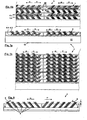
- FIGS. 1 to 15 In various views, several embodiments of a cleaning device 1 for contaminated and / or contaminated surfaces, in particular for running surfaces L of tires R of vehicles not shown here, shown.
- the cleaning device 1 has a brush device 2 for the cleaning treatment of the running surfaces L, which comprises brushes 3 with bristle carriers 4 and bristles 5.
- the bristles 5 are combined to bristle tufts 6.
- the bristle carrier 4 are each formed as a brush strip 7.
- the cleaning device 1 further comprises a support device 8 for supporting the running surfaces L in a support plane E, wherein the support plane E limits a working space A for the running surfaces L, which is arranged in all figures above the support plane E.
- the bristles 5 extend in the bristle tufts 6 with their free ends 9 to the working space A, wherein the support plane E to a in Fig. 3a, 3c and 8th by way of example.
- the bristles 5 close with the support plane E in a rest position, an inclination angle ß greater than 0 ° and less than 90 °, here exemplifying about 35 °, the bristles 5, except for in Figures 2b and 3b , reproduced in the figures in the rest position.
- All embodiments of the cleaning device 1 described here by way of example are designed for a main movement direction h, in which the vehicles can be moved in a translational movement b x over the support plane E. Furthermore, here the bristles 5 and the bristle tufts 6 extend perpendicular to the main direction of movement h.
- the support device 8 comprises a frame 10 with parallel spaced rods 11, 12, wherein the rods 11, 12 each have narrow sides 13 and large side surface 14 and the working space A facing narrow sides 13, the support plane E. form.
- the rods 11, 12 enclose a box-shaped intermediate space 15, in which the brush 3 is arranged.
- the tire R moves in a rotational movement b r in the main direction of movement h, wherein due to the rotational movement b r of the tire R at the same time a movement by the tread perpendicular to the movement b x in the x-direction or in the main direction of movement h hdeci follows and the tread L on the Support plane E unrolls.
- the bristle tufts 6 and the bristles 5 with their free ends 9 when passing over the support plane E from an in Fig.
- the rods 11, 12 are generally perpendicular to each other and thus arranged like a grid.
- the FIGS. 4 to 8 essentially serve to demonstrate possible arrangements of the bristle tufts 6.
- the rods 11, 12 are arranged like a lattice.
- a plurality of rows 6.1 are provided with bristles 6, not all of which are shown here.
- the bristles 5 in the bristle tufts 6 extend with a component in the first direction r 1 perpendicular to the main movement direction h, wherein the bristle rows 6.1 staggered one behind the other in spaces 15 between the rods 11, 12 are arranged.
- the bristle tufts 6 of a front second row 6.1 extend here in a second direction r 2
- the bristle tufts 6 of the subsequent first row 6.1 extend in the first direction r 1 .
- the bristle tufts 6 with respect to the main direction of movement h are arranged one behind the other
- the bristle tufts 6 in the fourth embodiment according to Fig. 5b set to "gap".
- the latter embodiment offers the advantage that the running surface L can be cleaned more completely.
- FIGS. 6 to 7 embodiments of the cleaning device 1 are shown, in which the bristle carrier 4 each have two rows 6.1, 6.2 with bristle tufts 6. While in the embodiments according to Fig. 6a and 6b the Bristle tufts 6 of a brush strip 7 point in one direction, the peat tufts 6 in the embodiments according to Fig. 7a and 7b a first row 6.1 in the first direction r 1 and that of a second row 6.2 in the second direction r 2 shown.
- the inclination of the bristle tufts 6 of a bristle strip 7 in two directions r 1 , r 2 causes the frictional forces that arise with scraping of the free ends 9 on the running surface L, with respect to the brush strip 7 at least approximately cancel.
- Exemplary is also in FIG. 6a shown that the brush strips 7 for mounting their length in an insertion direction e in the support device 8 are inserted.
- FIG. 8 an eighth embodiment of the cleaning device 1 is shown, in which the brush 3 is equipped with a series bristle tufts 6.
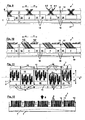
- FIGS. 9 to 15 schematically reproduced embodiments of the cleaning device 1 differ from the preceding particular in that the brush strips 7 each with its longitudinal direction 1 in the main direction of movement h and thus, except for in FIGS. 11 and 12 , perpendicular to the image plane.
- the brush strip 7 each have two rows 6.1, 6.2 with bristle tufts 6, the bristle tufts 6 of a first row 6.1 in the first direction r 1 and the bristle tufts 6 of the other row 6.2 are inclined in the second direction r 2 .
- the bristles 5 When driving over the cleaning device 1 thus, as in the previous embodiments, the bristles 5 are bent about a bending axis c, which runs in the main direction of movement h and here perpendicular to the image plane, so that the free ends 9 of the bristles 5 perpendicular to the main movement direction h along the tread Scrape or brush L along.
- a rod formed as a first rod 11 extends in each case in the longitudinal direction 1 of the brush strip 7, with its narrow side 13 facing away from the support plane E resting on a substrate U.
- the second rod 12 is designed to be smaller in height than the first rod 11. Since he forms the support plane E with his the working space A facing narrow side 13, he is with its the receiving space A remote narrow side 13 so spaced from the substrate U. It arises between the second rod 12 and the substrate U a spacing space 17 through which the brush bar 7 is guided. Thanks to this construction, the brush bar 7 can be inserted laterally in the longitudinal direction 1 of the first bars 11 in the intermediate spaces 15 or removed again. According to FIG. 9 the Bostenbüschel 6 are arranged crossing each other.
- the feature of the cleaning device 1 is that the rods 11, 12 are welded one behind the other at least in some of their points of intersection.
- the cleaning device 1 has an in Fig. 9 Tray 16 shown for receiving beautter dirt particles on.
- the brush strips 7 are arranged at a distance from the first bars 11 and provided for collecting tray 16 leading through holes 18 through which the dirt particles can get into the sump 16.
- FIGS. 10 to 12 Tenth embodiment of the cleaning device 1 shown differs from the ninth embodiment of the cleaning device 1 in that several in one direction.
- r 1 , r 2 effective and parallel aligned Bostenbüschel 6 are arranged as a group in the brush strip 7.
- FIG. 11 can be removed, that in each case in a grid field 19, which is formed by the intersecting rods 11, 12, a group of Bostenbüscheln 6, here nine Bostenbüscheln 6, is arranged, each in the adjacent grid array 19, a group of Bostenbüscheln 6 is positioned which are oriented opposite to the others with respect to the direction r.
- FIG. 12 is based on a second side view of the tenth embodiment of the cleaning device 1 according to FIG. 10 another possible feature of the cleaning device 1 is reproduced as a schematic, which says that the brush channel 7 of the brush 3 has a curved course in its longitudinal direction. As a result, the brush strip 7 is bent upward here.
- the course is dashed in the illustration and, for the sake of clarity, exaggerated in terms of bending.
- load B such as by overtravel tires, the brush bar 7 is elastically deformed against its bending down into a stretched or wier curved shape. This condition is indicated by a solid line.
- the brush bar 7 With relief, ie when the tire has passed over the brush bar 7, the brush bar 7 returns elastically in its curved shape and proposes the underside of here middle second bars 12, under which it is guided. As a result of this impact, dirt particles accumulated as a result of the cleaning process can detach from the free ends 9 of the bristles 5 or shake off and fall into the drip pan 16.
- a further feature of the cleaning device 1 is shown according to which the support device 8 and the brushes 3 are arranged in a fluid-tight tub 20 with a bottom 21 and circumferential side walls 22 for receiving a fluid F.
- This fluid F may be, for example, a cleaning agent, a decontamination agent and / or a disinfectant.
- equalization openings 23 are provided in order to maintain an equal high fluid level S in the cleaning device 1.
- the embodiments of the cleaning device 1 according to the FIGS. 10 to 12 Among other things, they differ from one another in that the maximum fluid level S can be of different height with respect to the bristles 5.
- the bristles 5 are made of polyamide in the embodiments shown here and thus are not absorbent, due to a capillary fluid F between the bristles 5 in tightly fitting bristles 5 to the free ends 9 of the bristles 5 are sucked high. As a result, a running surface L guided over the bristle ends 9 can be wetted along a path over which the free ends 9 of the bristles 5 are guided along the running surface L while bending them.
- a stronger wetting of the tread L can be achieved by, as in Fig. 14 represented, the support plane E is overflowed by the fluid F, that is, the fluid level S is disposed above the support plane E.
- the running surfaces L are wetted at the moment of their resting on the support plane E.
- the support device 8 with the brushes 3 in the twelfth embodiment according to Fig. 14 used as insert 25 in the tub 20 and therefore can be easily removed from the same again.
- the cleaning device 1 extends the fluid level S to over the free ends 9 of the bristles 5.
- brush the free bristle ends 9 completely over the tread R within the fluid F over the tread R, so that here can be spoken of a complete wet cleaning of the treads L.
- the side walls 22 of the tub 20 are formed in this embodiment by first rods 11 and second rods 12, but these extend over the entire height of the tub 20.
- the bristle tufts 6 of a row are inclined in two directions r 1 and r 2 . In this case, the bristle tufts 6 alternate in the longitudinal direction of the brush strip 7. This embodiment is best suited, for example, for use in disinfection locks in restricted areas due to the occurrence of bird flu, foot-and-mouth disease or the like.
Landscapes
- Engineering & Computer Science (AREA)
- Mechanical Engineering (AREA)
- Vehicle Cleaning, Maintenance, Repair, Refitting, And Outriggers (AREA)
Claims (14)
- Dispositif de nettoyage (1) pour des surfaces sales et/ou contaminées, notamment pour des portées de chaussures ou de pneus de véhicules, le dispositif de nettoyage (1) comprenant un dispositif de brosse (2) avec des brosses (3) comportant un support de soies (4) et des soies (5) pour le traitement nettoyant des portées (L) ainsi qu'un dispositif de support (8) pour supporter les portées (L) dans un plan de support (E), le plan de support (E) délimitant un compartiment de travail (A) pour les portées (L), et les soies (5) s'étendant chacune vers le compartiment de travail (A) et vers le plan de support (E) par une extrémité libre (9), les soies (5), dans une position de repos, incluant avec le plan de support (E) un angle d'inclinaison (β) supérieur à 0° et inférieur à 90° et les soies pénétrant avec ses extrémités libres (9) par le plan de support (E) et dépassant le plan de support (E) par un montant (a), caractérisé en ce que le dispositif de nettoyage (1) est conçu pour une direction principale de mouvement (h) dans laquelle les véhicules peuvent rouler sur le plan de support (E) ou les portées de chaussures peuvent être déroulées contre le plan de support (E) et en ce que les soies (5) s'étendent longitudinalement dans ou verticalement par rapport à la direction principale de mouvement (h).
- Dispositif de nettoyage selon la revendication 1, caractérisé en ce que les supports de soies (4) sont arrangés statiquement par rapport au plan de support (E).
- Dispositif de nettoyage selon les revendications 1 ou 2, caractérisé en ce que l'angle d'inclinaison (β) est supérieur à 30° et inférieur à 85°.
- Dispositif de nettoyage selon l'une des revendications 1 à 3, caractérisé en ce que l'angle d'inclinaison (β) est supérieur à 60° et inférieur à 80°.
- Dispositif de nettoyage selon l'une des revendications 1 à 4, caractérisé en ce que les soies (5) s'étendent longitudinalement et perpendiculairement à la direction principale de mouvement à parts égales ou à peu près égales vers les deux directions (r1, r2), par rapport au plan de support (E).
- Dispositif de nettoyage selon l'une des revendications 1 à 4, caractérisé en ce que les soies (5) sont combinées en touffes de soies (6) arrangées en un (6.1) ou plusieurs rangs (6.1, 6.2) individuellement ou en groupes de plusieurs touffes de soies (6) d'une même direction d'extension sur le support de soies (4).
- Dispositif de nettoyage selon l'une des revendications 1 à 6, caractérisé en ce que les soies (5) sont, par rapport au plan de support (E), arrangées en un premier rang (6.1) avec une composante dans une première direction (r1) perpendiculaire à la direction principale de mouvement (h) et en un deuxième rang (6.2) avec une composante dans une deuxième direction (r2) opposée à la première direction et perpendiculaire à la direction principale de mouvement (h).
- Dispositif de nettoyage selon les revendications 6 ou 7, caractérisé en ce que les rangs (6.1, 6.2) sont arrangés de manière parallèle et alternante l'un par rapport à l'autre.
- Dispositif de nettoyage selon la revendication 8, caractérisé en ce qu'un nombre paire de rangs alternants est arrangé sur chacun des supports de soies (4).
- Dispositif de nettoyage selon l'une des revendications 6 à 9, caractérisé en ce que les rangs (6.1, 6.2) s'étendent longitudinalement dans ou perpendiculairement à la direction principale de mouvement (h).
- Dispositif de nettoyage selon la revendication 10, caractérisé en ce que le support de soies (4) est agencé comme de barrette de brosse (7).
- Dispositif de nettoyage selon la revendication 11, caractérisé en ce que la barrette de brosse (7) est arquée dans la direction longitudinale (I).
- Dispositif de nettoyage selon la revendication 13, caractérisé en ce que la barrette de brosse (7) est cambrée au milieu vers le plan de support (E).
- Dispositif de nettoyage selon l'une des revendications 1 à 13, caractérisé en ce que des interstices existent entre les soies (5) dans les touffes de soies (6), lesdits interstices aspirant des liquides ou fluides mouillants par suite de l'effet de capillarité.
Priority Applications (2)
| Application Number | Priority Date | Filing Date | Title |
|---|---|---|---|
| PL09703752T PL2240066T3 (pl) | 2008-01-25 | 2009-01-22 | Urządzenie czyszczące |
| SI200930615T SI2240066T1 (sl) | 2008-01-25 | 2009-01-22 | ÄŚistilna naprava |
Applications Claiming Priority (2)
| Application Number | Priority Date | Filing Date | Title |
|---|---|---|---|
| DE202008001109U DE202008001109U1 (de) | 2008-01-25 | 2008-01-25 | Reinigungsvorrichtung |
| PCT/EP2009/000375 WO2009092578A2 (fr) | 2008-01-25 | 2009-01-22 | Dispositif de nettoyage |
Publications (2)
| Publication Number | Publication Date |
|---|---|
| EP2240066A2 EP2240066A2 (fr) | 2010-10-20 |
| EP2240066B1 true EP2240066B1 (fr) | 2013-03-20 |
Family
ID=39326847
Family Applications (1)
| Application Number | Title | Priority Date | Filing Date |
|---|---|---|---|
| EP09703752A Active EP2240066B1 (fr) | 2008-01-25 | 2009-01-22 | Dispositif de nettoyage |
Country Status (7)
| Country | Link |
|---|---|
| EP (1) | EP2240066B1 (fr) |
| DE (1) | DE202008001109U1 (fr) |
| DK (1) | DK2240066T3 (fr) |
| ES (1) | ES2418879T3 (fr) |
| PL (1) | PL2240066T3 (fr) |
| SI (1) | SI2240066T1 (fr) |
| WO (1) | WO2009092578A2 (fr) |
Families Citing this family (5)
| Publication number | Priority date | Publication date | Assignee | Title |
|---|---|---|---|---|
| ITUD20090093A1 (it) * | 2009-05-11 | 2010-11-12 | Martik S R L | Dispositivo di pulizia a spazzole e relativo procedimento |
| WO2015127963A1 (fr) * | 2014-02-25 | 2015-09-03 | Maschinenfabrik Heute Gmbh & Co. Kg | Languette de brosse, unité de brosse et dispositif de nettoyage |
| US9221431B2 (en) * | 2014-04-29 | 2015-12-29 | Sami Movsesian | Wheel cleaning mat |
| CN108602492B (zh) * | 2016-01-21 | 2021-09-03 | 孚瑞锑格股份公司 | 带有清洗水管的轮胎清洗设备 |
| FI129227B (fi) | 2019-08-26 | 2021-09-30 | Juha Karppinen | Järjestely ajoneuvon renkaiden puhdistamiseksi |
Family Cites Families (7)
| Publication number | Priority date | Publication date | Assignee | Title |
|---|---|---|---|---|
| GB399129A (en) * | 1933-05-27 | 1933-09-28 | Louis Rostoker | Improvements in or relating to door mats |
| US2989766A (en) * | 1959-04-17 | 1961-06-27 | Charles R Hoag | Bristle anchorine structure and article |
| DE7520999U (de) * | 1975-07-02 | 1975-11-13 | Alveru Sa | Vorrichtung zum Säubern des Schuhwerkes |
| JPS59140149A (ja) * | 1982-11-22 | 1984-08-11 | Nippon Unit Kogyo Seisakusho:Kk | 車両、特に重車両車輪の泥落しマツト |
| NO890060L (no) * | 1989-01-06 | 1990-07-09 | Tommy Selnes | Apparat for rensing av dekkbanen paa kjoeretoeyhjul. |
| DE10219780A1 (de) * | 2002-05-03 | 2003-11-13 | Ecolab Gmbh & Co Ohg | Vorrichtung zur Erzeugung eines Schaumteppichs, damit ausgestattete Hygiene-Schleuse, Behandlungsverfahren und Verwendung der Vorrichtung |
| DE20212289U1 (de) | 2002-08-09 | 2002-11-21 | Maschinenfabrik A. u. W. Heute GmbH & Co, 42657 Solingen | Vorrichtung zum Reinigen von Schuhsohlen |
-
2008
- 2008-01-25 DE DE202008001109U patent/DE202008001109U1/de not_active Expired - Lifetime
-
2009
- 2009-01-22 WO PCT/EP2009/000375 patent/WO2009092578A2/fr not_active Ceased
- 2009-01-22 ES ES09703752T patent/ES2418879T3/es active Active
- 2009-01-22 SI SI200930615T patent/SI2240066T1/sl unknown
- 2009-01-22 EP EP09703752A patent/EP2240066B1/fr active Active
- 2009-01-22 DK DK09703752.7T patent/DK2240066T3/da active
- 2009-01-22 PL PL09703752T patent/PL2240066T3/pl unknown
Also Published As
| Publication number | Publication date |
|---|---|
| SI2240066T1 (sl) | 2013-10-30 |
| WO2009092578A3 (fr) | 2009-11-12 |
| EP2240066A2 (fr) | 2010-10-20 |
| ES2418879T3 (es) | 2013-08-16 |
| WO2009092578A2 (fr) | 2009-07-30 |
| DK2240066T3 (da) | 2013-06-03 |
| PL2240066T3 (pl) | 2013-08-30 |
| DE202008001109U1 (de) | 2008-04-24 |
Similar Documents
| Publication | Publication Date | Title |
|---|---|---|
| DE69322422T2 (de) | Lippe für Wischgerät | |
| EP0595947B1 (fr) | Bavette garde-boue pour vehicules | |
| DE69526959T2 (de) | Bürstenanordnung für eine zahnbürste | |
| EP2240066B1 (fr) | Dispositif de nettoyage | |
| EP0337110A1 (fr) | Caniveau d'évacuation d'eau de surface | |
| EP0289880A2 (fr) | Grille pour la construction de tapis ou décrottoirs | |
| EP0910275B1 (fr) | Corps nettoyeur souple et a pores ouverts | |
| DE4106496C2 (de) | Laufmatte und/oder Fußabstreifer | |
| WO2015127963A1 (fr) | Languette de brosse, unité de brosse et dispositif de nettoyage | |
| EP0059886B1 (fr) | Grille pour paillasson ou décrottoir | |
| EP0955005B1 (fr) | Paillasson | |
| WO2019145055A1 (fr) | Rouleau de nettoyage rotatif et dispositif de balayage muni de ce rouleau | |
| DE102018112992A1 (de) | Reinigungstuch für eine Reinigungseinrichtung | |
| DE3103290C2 (de) | "Fußraummatte aus Gummi, Kunststoff o.dgl. für Kraftfahrzeuge" | |
| DE2412151A1 (de) | Rost oder matte, beispielsweise zur begehbaren abdeckung von rinnen, becken, gruben oder als fussabtreter | |
| DE202021100605U1 (de) | Schiebebesen | |
| EP4286236A1 (fr) | Système de marchepied pour un véhicule | |
| DE102011051141A1 (de) | Bodendüse für einen Staubsauger und Staubsauger mit einer solchen Bodendüse | |
| DE102005041869A1 (de) | Staubsaugerdüse mit Bürstenleiste | |
| DE102020000419B4 (de) | Installation zum Sammeln und Ableiten von Abwasser oder Regenwasser | |
| AT413074B (de) | Vorsatzgerät für einen staubsauger | |
| DE202023000910U1 (de) | Boden-Wischmopp-Abstreifvorrichtung | |
| DE102013112222A1 (de) | Fußmatte | |
| DE1901503U (de) | Matte. | |
| DE202014006582U1 (de) | Zweireihiger Besen bzw. Bürstenkörper mit Besatz |
Legal Events
| Date | Code | Title | Description |
|---|---|---|---|
| PUAI | Public reference made under article 153(3) epc to a published international application that has entered the european phase |
Free format text: ORIGINAL CODE: 0009012 |
|
| 17P | Request for examination filed |
Effective date: 20100819 |
|
| AK | Designated contracting states |
Kind code of ref document: A2 Designated state(s): AT BE BG CH CY CZ DE DK EE ES FI FR GB GR HR HU IE IS IT LI LT LU LV MC MK MT NL NO PL PT RO SE SI SK TR |
|
| AX | Request for extension of the european patent |
Extension state: AL BA RS |
|
| DAX | Request for extension of the european patent (deleted) | ||
| GRAP | Despatch of communication of intention to grant a patent |
Free format text: ORIGINAL CODE: EPIDOSNIGR1 |
|
| GRAS | Grant fee paid |
Free format text: ORIGINAL CODE: EPIDOSNIGR3 |
|
| GRAA | (expected) grant |
Free format text: ORIGINAL CODE: 0009210 |
|
| AK | Designated contracting states |
Kind code of ref document: B1 Designated state(s): AT BE BG CH CY CZ DE DK EE ES FI FR GB GR HR HU IE IS IT LI LT LU LV MC MK MT NL NO PL PT RO SE SI SK TR |
|
| REG | Reference to a national code |
Ref country code: GB Ref legal event code: FG4D Free format text: NOT ENGLISH |
|
| REG | Reference to a national code |
Ref country code: CH Ref legal event code: EP |
|
| REG | Reference to a national code |
Ref country code: IE Ref legal event code: FG4D Free format text: LANGUAGE OF EP DOCUMENT: GERMAN |
|
| REG | Reference to a national code |
Ref country code: AT Ref legal event code: REF Ref document number: 601535 Country of ref document: AT Kind code of ref document: T Effective date: 20130415 |
|
| REG | Reference to a national code |
Ref country code: CH Ref legal event code: NV Representative=s name: KATZAROV S.A., CH |
|
| REG | Reference to a national code |
Ref country code: DE Ref legal event code: R096 Ref document number: 502009006564 Country of ref document: DE Effective date: 20130508 |
|
| REG | Reference to a national code |
Ref country code: RO Ref legal event code: EPE |
|
| REG | Reference to a national code |
Ref country code: DK Ref legal event code: T3 |
|
| REG | Reference to a national code |
Ref country code: SE Ref legal event code: TRGR |
|
| PG25 | Lapsed in a contracting state [announced via postgrant information from national office to epo] |
Ref country code: LT Free format text: LAPSE BECAUSE OF FAILURE TO SUBMIT A TRANSLATION OF THE DESCRIPTION OR TO PAY THE FEE WITHIN THE PRESCRIBED TIME-LIMIT Effective date: 20130320 |
|
| REG | Reference to a national code |
Ref country code: NL Ref legal event code: T3 |
|
| REG | Reference to a national code |
Ref country code: SK Ref legal event code: T3 Ref document number: E 14113 Country of ref document: SK |
|
| REG | Reference to a national code |
Ref country code: NO Ref legal event code: T2 Effective date: 20130320 |
|
| REG | Reference to a national code |
Ref country code: ES Ref legal event code: FG2A Ref document number: 2418879 Country of ref document: ES Kind code of ref document: T3 Effective date: 20130816 |
|
| REG | Reference to a national code |
Ref country code: LT Ref legal event code: MG4D |
|
| PG25 | Lapsed in a contracting state [announced via postgrant information from national office to epo] |
Ref country code: FI Free format text: LAPSE BECAUSE OF FAILURE TO SUBMIT A TRANSLATION OF THE DESCRIPTION OR TO PAY THE FEE WITHIN THE PRESCRIBED TIME-LIMIT Effective date: 20130320 Ref country code: LV Free format text: LAPSE BECAUSE OF FAILURE TO SUBMIT A TRANSLATION OF THE DESCRIPTION OR TO PAY THE FEE WITHIN THE PRESCRIBED TIME-LIMIT Effective date: 20130320 Ref country code: GR Free format text: LAPSE BECAUSE OF FAILURE TO SUBMIT A TRANSLATION OF THE DESCRIPTION OR TO PAY THE FEE WITHIN THE PRESCRIBED TIME-LIMIT Effective date: 20130621 |
|
| REG | Reference to a national code |
Ref country code: PL Ref legal event code: T3 |
|
| PG25 | Lapsed in a contracting state [announced via postgrant information from national office to epo] |
Ref country code: HR Free format text: LAPSE BECAUSE OF FAILURE TO SUBMIT A TRANSLATION OF THE DESCRIPTION OR TO PAY THE FEE WITHIN THE PRESCRIBED TIME-LIMIT Effective date: 20130320 |
|
| REG | Reference to a national code |
Ref country code: HU Ref legal event code: AG4A Ref document number: E017113 Country of ref document: HU |
|
| PG25 | Lapsed in a contracting state [announced via postgrant information from national office to epo] |
Ref country code: EE Free format text: LAPSE BECAUSE OF FAILURE TO SUBMIT A TRANSLATION OF THE DESCRIPTION OR TO PAY THE FEE WITHIN THE PRESCRIBED TIME-LIMIT Effective date: 20130320 Ref country code: IS Free format text: LAPSE BECAUSE OF FAILURE TO SUBMIT A TRANSLATION OF THE DESCRIPTION OR TO PAY THE FEE WITHIN THE PRESCRIBED TIME-LIMIT Effective date: 20130720 Ref country code: PT Free format text: LAPSE BECAUSE OF FAILURE TO SUBMIT A TRANSLATION OF THE DESCRIPTION OR TO PAY THE FEE WITHIN THE PRESCRIBED TIME-LIMIT Effective date: 20130722 |
|
| PG25 | Lapsed in a contracting state [announced via postgrant information from national office to epo] |
Ref country code: CY Free format text: LAPSE BECAUSE OF FAILURE TO SUBMIT A TRANSLATION OF THE DESCRIPTION OR TO PAY THE FEE WITHIN THE PRESCRIBED TIME-LIMIT Effective date: 20130320 |
|
| PLBE | No opposition filed within time limit |
Free format text: ORIGINAL CODE: 0009261 |
|
| STAA | Information on the status of an ep patent application or granted ep patent |
Free format text: STATUS: NO OPPOSITION FILED WITHIN TIME LIMIT |
|
| 26N | No opposition filed |
Effective date: 20140102 |
|
| REG | Reference to a national code |
Ref country code: DE Ref legal event code: R097 Ref document number: 502009006564 Country of ref document: DE Effective date: 20140102 |
|
| PG25 | Lapsed in a contracting state [announced via postgrant information from national office to epo] |
Ref country code: MC Free format text: LAPSE BECAUSE OF FAILURE TO SUBMIT A TRANSLATION OF THE DESCRIPTION OR TO PAY THE FEE WITHIN THE PRESCRIBED TIME-LIMIT Effective date: 20130320 Ref country code: LU Free format text: LAPSE BECAUSE OF FAILURE TO SUBMIT A TRANSLATION OF THE DESCRIPTION OR TO PAY THE FEE WITHIN THE PRESCRIBED TIME-LIMIT Effective date: 20140122 |
|
| REG | Reference to a national code |
Ref country code: IE Ref legal event code: MM4A |
|
| REG | Reference to a national code |
Ref country code: FR Ref legal event code: PLFP Year of fee payment: 7 |
|
| PG25 | Lapsed in a contracting state [announced via postgrant information from national office to epo] |
Ref country code: IE Free format text: LAPSE BECAUSE OF NON-PAYMENT OF DUE FEES Effective date: 20140122 |
|
| REG | Reference to a national code |
Ref country code: FR Ref legal event code: PLFP Year of fee payment: 8 |
|
| PG25 | Lapsed in a contracting state [announced via postgrant information from national office to epo] |
Ref country code: MT Free format text: LAPSE BECAUSE OF FAILURE TO SUBMIT A TRANSLATION OF THE DESCRIPTION OR TO PAY THE FEE WITHIN THE PRESCRIBED TIME-LIMIT Effective date: 20130320 |
|
| REG | Reference to a national code |
Ref country code: FR Ref legal event code: PLFP Year of fee payment: 9 |
|
| REG | Reference to a national code |
Ref country code: FR Ref legal event code: PLFP Year of fee payment: 10 |
|
| REG | Reference to a national code |
Ref country code: DE Ref legal event code: R082 Ref document number: 502009006564 Country of ref document: DE Representative=s name: LIPPERT STACHOW PATENTANWAELTE RECHTSANWAELTE , DE Ref country code: DE Ref legal event code: R081 Ref document number: 502009006564 Country of ref document: DE Owner name: HEUTE MASCHINENFABRIK GMBH & CO. KG, DE Free format text: FORMER OWNER: MASCHINENFABRIK HEUTE GMBH & CO. KG, 42657 SOLINGEN, DE |
|
| REG | Reference to a national code |
Ref country code: NO Ref legal event code: CHAD Owner name: HEUTE MASCHINENFABRIK GMBH & CO KG, DE |
|
| REG | Reference to a national code |
Ref country code: HU Ref legal event code: HC9C Owner name: HEUTE MASCHINENFABRIK GMBH & CO. KG, DE Free format text: FORMER OWNER(S): MASCHINENFABRIK HEUTE GMBH & CO. KG, DE Ref country code: CH Ref legal event code: PCAR Free format text: NEW ADDRESS: AVENUE DES MORGINES 12, 1213 PETIT-LANCY (CH) Ref country code: CH Ref legal event code: PFA Owner name: HEUTE MASCHINENFABRIK GMBH AND CO. KG, DE Free format text: FORMER OWNER: MASCHINENFABRIK HEUTE GMBH AND CO. KG, DE Ref country code: BE Ref legal event code: HC Owner name: HEUTE MASCHINENFABRIK GMBH & CO. KG; DE Free format text: DETAILS ASSIGNMENT: CHANGE OF OWNER(S), CHANGEMENT DE NOM DU PROPRIETAIRE; FORMER OWNER NAME: MASCHINENFABRIK HEUTE GMBH & CO. KG Effective date: 20180126 |
|
| REG | Reference to a national code |
Ref country code: NL Ref legal event code: HC Owner name: HEUTE MASCHINENFABRIK GMBH & CO. KG; DE Free format text: DETAILS ASSIGNMENT: CHANGE OF OWNER(S), CHANGE OF OWNER(S) NAME; FORMER OWNER NAME: MASCHINENFABRIK HEUTE GMBH & CO. KG Effective date: 20180125 |
|
| REG | Reference to a national code |
Ref country code: ES Ref legal event code: PC2A Owner name: HEUTE MASCHINENFABRIK GMBH & CO. KG Effective date: 20180314 |
|
| REG | Reference to a national code |
Ref country code: SI Ref legal event code: SP73 Owner name: HEUTE MASCHINENFABRIK GMBH & CO. KG; DE Effective date: 20180313 |
|
| REG | Reference to a national code |
Ref country code: SK Ref legal event code: TC4A Ref document number: E 14113 Country of ref document: SK Owner name: HEUTE MASCHINENFABRIK GMBH & CO. KG, SOLINGEN, DE Effective date: 20180425 |
|
| REG | Reference to a national code |
Ref country code: AT Ref legal event code: HC Ref document number: 601535 Country of ref document: AT Kind code of ref document: T Owner name: HEUTE MASCHINENFABRIK GMBH & CO. KG, DE Effective date: 20180326 |
|
| REG | Reference to a national code |
Ref country code: FR Ref legal event code: CD Owner name: HEUTE MASCHINENFABRIK GMBH & CO. KG, DE Effective date: 20180504 |
|
| PG25 | Lapsed in a contracting state [announced via postgrant information from national office to epo] |
Ref country code: MK Free format text: LAPSE BECAUSE OF FAILURE TO SUBMIT A TRANSLATION OF THE DESCRIPTION OR TO PAY THE FEE WITHIN THE PRESCRIBED TIME-LIMIT Effective date: 20130320 |
|
| REG | Reference to a national code |
Ref country code: DE Ref legal event code: R008 Ref document number: 502009006564 Country of ref document: DE Ref country code: DE Ref legal event code: R039 Ref document number: 502009006564 Country of ref document: DE |
|
| REG | Reference to a national code |
Ref country code: DE Ref legal event code: R082 Ref document number: 502009006564 Country of ref document: DE Representative=s name: LIPPERT STACHOW PATENTANWAELTE RECHTSANWAELTE , DE |
|
| REG | Reference to a national code |
Ref country code: DE Ref legal event code: R040 Ref document number: 502009006564 Country of ref document: DE |
|
| PGFP | Annual fee paid to national office [announced via postgrant information from national office to epo] |
Ref country code: BG Payment date: 20250121 Year of fee payment: 17 |
|
| PGFP | Annual fee paid to national office [announced via postgrant information from national office to epo] |
Ref country code: SI Payment date: 20250109 Year of fee payment: 17 Ref country code: CH Payment date: 20250201 Year of fee payment: 17 |
|
| PGFP | Annual fee paid to national office [announced via postgrant information from national office to epo] |
Ref country code: PL Payment date: 20250110 Year of fee payment: 17 Ref country code: CZ Payment date: 20250110 Year of fee payment: 17 |
|
| PGFP | Annual fee paid to national office [announced via postgrant information from national office to epo] |
Ref country code: SK Payment date: 20250115 Year of fee payment: 17 |
|
| REG | Reference to a national code |
Ref country code: DE Ref legal event code: R081 Ref document number: 502009006564 Country of ref document: DE Owner name: HEUTE MASCHINENFABRIK GMBH & CO. KG, DE Free format text: FORMER OWNER: HEUTE MASCHINENFABRIK GMBH & CO. KG, 42657 SOLINGEN, DE |
|
| REG | Reference to a national code |
Ref country code: CH Ref legal event code: U11 Free format text: ST27 STATUS EVENT CODE: U-0-0-U10-U11 (AS PROVIDED BY THE NATIONAL OFFICE) Effective date: 20260201 |
|
| PGFP | Annual fee paid to national office [announced via postgrant information from national office to epo] |
Ref country code: NL Payment date: 20260121 Year of fee payment: 18 |
|
| PGFP | Annual fee paid to national office [announced via postgrant information from national office to epo] |
Ref country code: HU Payment date: 20260116 Year of fee payment: 18 |
|
| PGFP | Annual fee paid to national office [announced via postgrant information from national office to epo] |
Ref country code: SE Payment date: 20260121 Year of fee payment: 18 |
|
| PGFP | Annual fee paid to national office [announced via postgrant information from national office to epo] |
Ref country code: GB Payment date: 20260122 Year of fee payment: 18 |
|
| PGFP | Annual fee paid to national office [announced via postgrant information from national office to epo] |
Ref country code: ES Payment date: 20260217 Year of fee payment: 18 |
|
| PGFP | Annual fee paid to national office [announced via postgrant information from national office to epo] |
Ref country code: NO Payment date: 20260120 Year of fee payment: 18 Ref country code: DK Payment date: 20260115 Year of fee payment: 18 Ref country code: DE Payment date: 20260327 Year of fee payment: 18 |
|
| PGFP | Annual fee paid to national office [announced via postgrant information from national office to epo] |
Ref country code: AT Payment date: 20260119 Year of fee payment: 18 |
|
| PGFP | Annual fee paid to national office [announced via postgrant information from national office to epo] |
Ref country code: RO Payment date: 20260120 Year of fee payment: 18 Ref country code: IT Payment date: 20260130 Year of fee payment: 18 Ref country code: BE Payment date: 20260121 Year of fee payment: 18 |
|
| PGFP | Annual fee paid to national office [announced via postgrant information from national office to epo] |
Ref country code: FR Payment date: 20260128 Year of fee payment: 18 |
|
| PGFP | Annual fee paid to national office [announced via postgrant information from national office to epo] |
Ref country code: TR Payment date: 20260119 Year of fee payment: 18 |