EP4286607B1 - Système hydraulique et engin de chantier équipé d'un tel système hydraulique - Google Patents
Système hydraulique et engin de chantier équipé d'un tel système hydraulique Download PDFInfo
- Publication number
- EP4286607B1 EP4286607B1 EP23159071.2A EP23159071A EP4286607B1 EP 4286607 B1 EP4286607 B1 EP 4286607B1 EP 23159071 A EP23159071 A EP 23159071A EP 4286607 B1 EP4286607 B1 EP 4286607B1
- Authority
- EP
- European Patent Office
- Prior art keywords
- hydraulic
- pressure
- controlled
- consumer
- control
- Prior art date
- Legal status (The legal status is an assumption and is not a legal conclusion. Google has not performed a legal analysis and makes no representation as to the accuracy of the status listed.)
- Active
Links
Images


Classifications
-
- E—FIXED CONSTRUCTIONS
- E02—HYDRAULIC ENGINEERING; FOUNDATIONS; SOIL SHIFTING
- E02F—DREDGING; SOIL-SHIFTING
- E02F9/00—Component parts of dredgers or soil-shifting machines, not restricted to one of the kinds covered by groups E02F3/00 - E02F7/00
- E02F9/20—Drives; Control devices
- E02F9/22—Hydraulic or pneumatic drives
- E02F9/2278—Hydraulic circuits
- E02F9/2296—Systems with a variable displacement pump
-
- E—FIXED CONSTRUCTIONS
- E02—HYDRAULIC ENGINEERING; FOUNDATIONS; SOIL SHIFTING
- E02F—DREDGING; SOIL-SHIFTING
- E02F9/00—Component parts of dredgers or soil-shifting machines, not restricted to one of the kinds covered by groups E02F3/00 - E02F7/00
- E02F9/20—Drives; Control devices
- E02F9/22—Hydraulic or pneumatic drives
- E02F9/2221—Control of flow rate; Load sensing arrangements
- E02F9/2232—Control of flow rate; Load sensing arrangements using one or more variable displacement pumps
- E02F9/2235—Control of flow rate; Load sensing arrangements using one or more variable displacement pumps including an electronic controller
-
- F—MECHANICAL ENGINEERING; LIGHTING; HEATING; WEAPONS; BLASTING
- F15—FLUID-PRESSURE ACTUATORS; HYDRAULICS OR PNEUMATICS IN GENERAL
- F15B—SYSTEMS ACTING BY MEANS OF FLUIDS IN GENERAL; FLUID-PRESSURE ACTUATORS, e.g. SERVOMOTORS; DETAILS OF FLUID-PRESSURE SYSTEMS, NOT OTHERWISE PROVIDED FOR
- F15B11/00—Servomotor systems without provision for follow-up action; Circuits therefor
- F15B11/16—Servomotor systems without provision for follow-up action; Circuits therefor with two or more servomotors
- F15B11/161—Servomotor systems without provision for follow-up action; Circuits therefor with two or more servomotors with sensing of servomotor demand or load
- F15B11/165—Servomotor systems without provision for follow-up action; Circuits therefor with two or more servomotors with sensing of servomotor demand or load for adjusting the pump output or bypass in response to demand
-
- F—MECHANICAL ENGINEERING; LIGHTING; HEATING; WEAPONS; BLASTING
- F15—FLUID-PRESSURE ACTUATORS; HYDRAULICS OR PNEUMATICS IN GENERAL
- F15B—SYSTEMS ACTING BY MEANS OF FLUIDS IN GENERAL; FLUID-PRESSURE ACTUATORS, e.g. SERVOMOTORS; DETAILS OF FLUID-PRESSURE SYSTEMS, NOT OTHERWISE PROVIDED FOR
- F15B11/00—Servomotor systems without provision for follow-up action; Circuits therefor
- F15B11/16—Servomotor systems without provision for follow-up action; Circuits therefor with two or more servomotors
- F15B11/161—Servomotor systems without provision for follow-up action; Circuits therefor with two or more servomotors with sensing of servomotor demand or load
- F15B11/162—Servomotor systems without provision for follow-up action; Circuits therefor with two or more servomotors with sensing of servomotor demand or load for giving priority to particular servomotors or users
-
- F—MECHANICAL ENGINEERING; LIGHTING; HEATING; WEAPONS; BLASTING
- F15—FLUID-PRESSURE ACTUATORS; HYDRAULICS OR PNEUMATICS IN GENERAL
- F15B—SYSTEMS ACTING BY MEANS OF FLUIDS IN GENERAL; FLUID-PRESSURE ACTUATORS, e.g. SERVOMOTORS; DETAILS OF FLUID-PRESSURE SYSTEMS, NOT OTHERWISE PROVIDED FOR
- F15B2211/00—Circuits for servomotor systems
- F15B2211/20—Fluid pressure source, e.g. accumulator or variable axial piston pump
- F15B2211/205—Systems with pumps
- F15B2211/2053—Type of pump
- F15B2211/20546—Type of pump variable capacity
-
- F—MECHANICAL ENGINEERING; LIGHTING; HEATING; WEAPONS; BLASTING
- F15—FLUID-PRESSURE ACTUATORS; HYDRAULICS OR PNEUMATICS IN GENERAL
- F15B—SYSTEMS ACTING BY MEANS OF FLUIDS IN GENERAL; FLUID-PRESSURE ACTUATORS, e.g. SERVOMOTORS; DETAILS OF FLUID-PRESSURE SYSTEMS, NOT OTHERWISE PROVIDED FOR
- F15B2211/00—Circuits for servomotor systems
- F15B2211/30—Directional control
- F15B2211/305—Directional control characterised by the type of valves
- F15B2211/3056—Assemblies of multiple valves
- F15B2211/3059—Assemblies of multiple valves having multiple valves for multiple output members
-
- F—MECHANICAL ENGINEERING; LIGHTING; HEATING; WEAPONS; BLASTING
- F15—FLUID-PRESSURE ACTUATORS; HYDRAULICS OR PNEUMATICS IN GENERAL
- F15B—SYSTEMS ACTING BY MEANS OF FLUIDS IN GENERAL; FLUID-PRESSURE ACTUATORS, e.g. SERVOMOTORS; DETAILS OF FLUID-PRESSURE SYSTEMS, NOT OTHERWISE PROVIDED FOR
- F15B2211/00—Circuits for servomotor systems
- F15B2211/30—Directional control
- F15B2211/32—Directional control characterised by the type of actuation
- F15B2211/321—Directional control characterised by the type of actuation mechanically
- F15B2211/324—Directional control characterised by the type of actuation mechanically manually, e.g. by using a lever or pedal
-
- F—MECHANICAL ENGINEERING; LIGHTING; HEATING; WEAPONS; BLASTING
- F15—FLUID-PRESSURE ACTUATORS; HYDRAULICS OR PNEUMATICS IN GENERAL
- F15B—SYSTEMS ACTING BY MEANS OF FLUIDS IN GENERAL; FLUID-PRESSURE ACTUATORS, e.g. SERVOMOTORS; DETAILS OF FLUID-PRESSURE SYSTEMS, NOT OTHERWISE PROVIDED FOR
- F15B2211/00—Circuits for servomotor systems
- F15B2211/30—Directional control
- F15B2211/365—Directional control combined with flow control and pressure control
-
- F—MECHANICAL ENGINEERING; LIGHTING; HEATING; WEAPONS; BLASTING
- F15—FLUID-PRESSURE ACTUATORS; HYDRAULICS OR PNEUMATICS IN GENERAL
- F15B—SYSTEMS ACTING BY MEANS OF FLUIDS IN GENERAL; FLUID-PRESSURE ACTUATORS, e.g. SERVOMOTORS; DETAILS OF FLUID-PRESSURE SYSTEMS, NOT OTHERWISE PROVIDED FOR
- F15B2211/00—Circuits for servomotor systems
- F15B2211/50—Pressure control
- F15B2211/505—Pressure control characterised by the type of pressure control means
- F15B2211/50554—Pressure control characterised by the type of pressure control means the pressure control means controlling a pressure downstream of the pressure control means, e.g. pressure reducing valve
-
- F—MECHANICAL ENGINEERING; LIGHTING; HEATING; WEAPONS; BLASTING
- F15—FLUID-PRESSURE ACTUATORS; HYDRAULICS OR PNEUMATICS IN GENERAL
- F15B—SYSTEMS ACTING BY MEANS OF FLUIDS IN GENERAL; FLUID-PRESSURE ACTUATORS, e.g. SERVOMOTORS; DETAILS OF FLUID-PRESSURE SYSTEMS, NOT OTHERWISE PROVIDED FOR
- F15B2211/00—Circuits for servomotor systems
- F15B2211/50—Pressure control
- F15B2211/515—Pressure control characterised by the connections of the pressure control means in the circuit
- F15B2211/5153—Pressure control characterised by the connections of the pressure control means in the circuit being connected to an output member and a directional control valve
-
- F—MECHANICAL ENGINEERING; LIGHTING; HEATING; WEAPONS; BLASTING
- F15—FLUID-PRESSURE ACTUATORS; HYDRAULICS OR PNEUMATICS IN GENERAL
- F15B—SYSTEMS ACTING BY MEANS OF FLUIDS IN GENERAL; FLUID-PRESSURE ACTUATORS, e.g. SERVOMOTORS; DETAILS OF FLUID-PRESSURE SYSTEMS, NOT OTHERWISE PROVIDED FOR
- F15B2211/00—Circuits for servomotor systems
- F15B2211/50—Pressure control
- F15B2211/515—Pressure control characterised by the connections of the pressure control means in the circuit
- F15B2211/5158—Pressure control characterised by the connections of the pressure control means in the circuit being connected to a pressure source and an output member
-
- F—MECHANICAL ENGINEERING; LIGHTING; HEATING; WEAPONS; BLASTING
- F15—FLUID-PRESSURE ACTUATORS; HYDRAULICS OR PNEUMATICS IN GENERAL
- F15B—SYSTEMS ACTING BY MEANS OF FLUIDS IN GENERAL; FLUID-PRESSURE ACTUATORS, e.g. SERVOMOTORS; DETAILS OF FLUID-PRESSURE SYSTEMS, NOT OTHERWISE PROVIDED FOR
- F15B2211/00—Circuits for servomotor systems
- F15B2211/50—Pressure control
- F15B2211/52—Pressure control characterised by the type of actuation
- F15B2211/526—Pressure control characterised by the type of actuation electrically or electronically
-
- F—MECHANICAL ENGINEERING; LIGHTING; HEATING; WEAPONS; BLASTING
- F15—FLUID-PRESSURE ACTUATORS; HYDRAULICS OR PNEUMATICS IN GENERAL
- F15B—SYSTEMS ACTING BY MEANS OF FLUIDS IN GENERAL; FLUID-PRESSURE ACTUATORS, e.g. SERVOMOTORS; DETAILS OF FLUID-PRESSURE SYSTEMS, NOT OTHERWISE PROVIDED FOR
- F15B2211/00—Circuits for servomotor systems
- F15B2211/60—Circuit components or control therefor
- F15B2211/61—Secondary circuits
- F15B2211/611—Diverting circuits, e.g. for cooling or filtering
-
- F—MECHANICAL ENGINEERING; LIGHTING; HEATING; WEAPONS; BLASTING
- F15—FLUID-PRESSURE ACTUATORS; HYDRAULICS OR PNEUMATICS IN GENERAL
- F15B—SYSTEMS ACTING BY MEANS OF FLUIDS IN GENERAL; FLUID-PRESSURE ACTUATORS, e.g. SERVOMOTORS; DETAILS OF FLUID-PRESSURE SYSTEMS, NOT OTHERWISE PROVIDED FOR
- F15B2211/00—Circuits for servomotor systems
- F15B2211/60—Circuit components or control therefor
- F15B2211/63—Electronic controllers
- F15B2211/6303—Electronic controllers using input signals
- F15B2211/6306—Electronic controllers using input signals representing a pressure
-
- F—MECHANICAL ENGINEERING; LIGHTING; HEATING; WEAPONS; BLASTING
- F15—FLUID-PRESSURE ACTUATORS; HYDRAULICS OR PNEUMATICS IN GENERAL
- F15B—SYSTEMS ACTING BY MEANS OF FLUIDS IN GENERAL; FLUID-PRESSURE ACTUATORS, e.g. SERVOMOTORS; DETAILS OF FLUID-PRESSURE SYSTEMS, NOT OTHERWISE PROVIDED FOR
- F15B2211/00—Circuits for servomotor systems
- F15B2211/60—Circuit components or control therefor
- F15B2211/63—Electronic controllers
- F15B2211/6303—Electronic controllers using input signals
- F15B2211/6346—Electronic controllers using input signals representing a state of input means, e.g. joystick position
-
- F—MECHANICAL ENGINEERING; LIGHTING; HEATING; WEAPONS; BLASTING
- F15—FLUID-PRESSURE ACTUATORS; HYDRAULICS OR PNEUMATICS IN GENERAL
- F15B—SYSTEMS ACTING BY MEANS OF FLUIDS IN GENERAL; FLUID-PRESSURE ACTUATORS, e.g. SERVOMOTORS; DETAILS OF FLUID-PRESSURE SYSTEMS, NOT OTHERWISE PROVIDED FOR
- F15B2211/00—Circuits for servomotor systems
- F15B2211/60—Circuit components or control therefor
- F15B2211/665—Methods of control using electronic components
-
- F—MECHANICAL ENGINEERING; LIGHTING; HEATING; WEAPONS; BLASTING
- F15—FLUID-PRESSURE ACTUATORS; HYDRAULICS OR PNEUMATICS IN GENERAL
- F15B—SYSTEMS ACTING BY MEANS OF FLUIDS IN GENERAL; FLUID-PRESSURE ACTUATORS, e.g. SERVOMOTORS; DETAILS OF FLUID-PRESSURE SYSTEMS, NOT OTHERWISE PROVIDED FOR
- F15B2211/00—Circuits for servomotor systems
- F15B2211/60—Circuit components or control therefor
- F15B2211/665—Methods of control using electronic components
- F15B2211/6652—Control of the pressure source, e.g. control of the swash plate angle
-
- F—MECHANICAL ENGINEERING; LIGHTING; HEATING; WEAPONS; BLASTING
- F15—FLUID-PRESSURE ACTUATORS; HYDRAULICS OR PNEUMATICS IN GENERAL
- F15B—SYSTEMS ACTING BY MEANS OF FLUIDS IN GENERAL; FLUID-PRESSURE ACTUATORS, e.g. SERVOMOTORS; DETAILS OF FLUID-PRESSURE SYSTEMS, NOT OTHERWISE PROVIDED FOR
- F15B2211/00—Circuits for servomotor systems
- F15B2211/60—Circuit components or control therefor
- F15B2211/665—Methods of control using electronic components
- F15B2211/6655—Power control, e.g. combined pressure and flow rate control
-
- F—MECHANICAL ENGINEERING; LIGHTING; HEATING; WEAPONS; BLASTING
- F15—FLUID-PRESSURE ACTUATORS; HYDRAULICS OR PNEUMATICS IN GENERAL
- F15B—SYSTEMS ACTING BY MEANS OF FLUIDS IN GENERAL; FLUID-PRESSURE ACTUATORS, e.g. SERVOMOTORS; DETAILS OF FLUID-PRESSURE SYSTEMS, NOT OTHERWISE PROVIDED FOR
- F15B2211/00—Circuits for servomotor systems
- F15B2211/70—Output members, e.g. hydraulic motors or cylinders or control therefor
- F15B2211/705—Output members, e.g. hydraulic motors or cylinders or control therefor characterised by the type of output members or actuators
- F15B2211/7051—Linear output members
- F15B2211/7053—Double-acting output members
- F15B2211/7054—Having equal piston areas
-
- F—MECHANICAL ENGINEERING; LIGHTING; HEATING; WEAPONS; BLASTING
- F15—FLUID-PRESSURE ACTUATORS; HYDRAULICS OR PNEUMATICS IN GENERAL
- F15B—SYSTEMS ACTING BY MEANS OF FLUIDS IN GENERAL; FLUID-PRESSURE ACTUATORS, e.g. SERVOMOTORS; DETAILS OF FLUID-PRESSURE SYSTEMS, NOT OTHERWISE PROVIDED FOR
- F15B2211/00—Circuits for servomotor systems
- F15B2211/70—Output members, e.g. hydraulic motors or cylinders or control therefor
- F15B2211/705—Output members, e.g. hydraulic motors or cylinders or control therefor characterised by the type of output members or actuators
- F15B2211/7058—Rotary output members
-
- F—MECHANICAL ENGINEERING; LIGHTING; HEATING; WEAPONS; BLASTING
- F15—FLUID-PRESSURE ACTUATORS; HYDRAULICS OR PNEUMATICS IN GENERAL
- F15B—SYSTEMS ACTING BY MEANS OF FLUIDS IN GENERAL; FLUID-PRESSURE ACTUATORS, e.g. SERVOMOTORS; DETAILS OF FLUID-PRESSURE SYSTEMS, NOT OTHERWISE PROVIDED FOR
- F15B2211/00—Circuits for servomotor systems
- F15B2211/70—Output members, e.g. hydraulic motors or cylinders or control therefor
- F15B2211/71—Multiple output members, e.g. multiple hydraulic motors or cylinders
- F15B2211/7135—Combinations of output members of different types, e.g. single-acting cylinders with rotary motors
-
- F—MECHANICAL ENGINEERING; LIGHTING; HEATING; WEAPONS; BLASTING
- F15—FLUID-PRESSURE ACTUATORS; HYDRAULICS OR PNEUMATICS IN GENERAL
- F15B—SYSTEMS ACTING BY MEANS OF FLUIDS IN GENERAL; FLUID-PRESSURE ACTUATORS, e.g. SERVOMOTORS; DETAILS OF FLUID-PRESSURE SYSTEMS, NOT OTHERWISE PROVIDED FOR
- F15B2211/00—Circuits for servomotor systems
- F15B2211/70—Output members, e.g. hydraulic motors or cylinders or control therefor
- F15B2211/78—Control of multiple output members
- F15B2211/781—Control of multiple output members one or more output members having priority
Definitions
- the present invention relates to a hydraulic system according to the preamble of claim 1 and to a working device, in particular a hydraulic excavator, with such a hydraulic system.
- main hydraulic circuit or working hydraulic circuit whose consumers are responsible for the functions of the equipment, and the remaining hydraulics with the auxiliary consumers (auxiliary consumer circuit).
- the working hydraulics are typically operated by an adjustable hydraulic pump and include all hydraulic components for carrying out the work functions, i.e. the operation of the equipment and the attachments.
- the auxiliary consumer circuit with the auxiliary consumers is usually operated by several differently controlled hydraulic pumps and provides other functions necessary for the operation of the construction machine.
- auxiliary consumers Given the different functions of the auxiliary consumers, they are often regulated in different ways. A basic distinction is made between pressure regulation and quantity regulation of the connected auxiliary consumers. Due to the different control concepts, the auxiliary consumers are therefore often fed by differently regulated auxiliary consumer pumps.
- the pressure-controlled auxiliary consumers are supplied via pressure-controlled hydraulic pumps and the quantity-controlled auxiliary consumers are supplied via separate quantity-controlled auxiliary consumer pumps.
- hydraulic steering and hydraulic braking systems are supplied with hydraulic oil using state-of-the-art constant-displacement pumps or load-sensing pumps or LS pumps.
- Fan drives are usually operated with pressure-controlled pumps.
- the pilot pressure generation for the main hydraulics is also often operated with constant-displacement pumps. Feed pumps are also required, for example for closed hydraulic systems.
- Newer systems such as those in US 6 314 729 B1 and US 6 848 255 B2 are operated by a LS pump.
- LS control of the various consumers is extremely susceptible to vibration.
- DE 10 2016 000 186 A1 a system with combined LS and pressure control for a common variable displacement pump.
- this control also has the disadvantage that it is somewhat susceptible to vibration.
- the present invention is therefore based on the object of overcoming the disadvantages of the prior art and of finding a suitable system that enables a stable joint supply of quantity-controlled and pressure-controlled consumers.
- a hydraulic system with at least two hydraulic consumers jointly supplied via an adjustable hydraulic pump and a control arrangement for controlling the hydraulic pump is proposed.
- at least one consumer is pressure-controlled and at least one consumer is quantity-controlled.
- the consumers supplied via the common hydraulic pump can be secondary consumers of a working machine, such as fans, steering, brakes and/or pilot control.
- the hydraulic system can be a secondary consumer circuit of a working machine or part of such a circuit.
- control arrangement comprises a control unit and a sensor system connected to the control unit for detecting at least one variable characterizing a requirement of at least one consumer.
- the requirement of the respective consumer preferably relates to a pressure provided by the hydraulic pump or a delivery volume provided.
- a detected variable can represent a requirement itself, for example a pressure detected by a pressure sensor.
- the requirement of a consumer can be derived from a detected variable or determined by the control unit.
- control device is designed to determine a pressure required by at least one pressure-controlled consumer and a volume flow required by at least one quantity-controlled consumer using the at least one variable detected by the sensor system and to control the hydraulic pump in such a way that the required pressure and the required volume flow are made available to the corresponding consumers.
- the required pressure for one or more pressure-controlled consumers is not determined based on sensor signals, but is stored as a fixed and/or definable value in a memory to which the control unit has access.
- the required volume flow is preferably derived from the signals of one or more sensors.
- the hydraulic system according to the invention makes it possible to supply several differently controlled consumers with one and the same hydraulic pump without having to pay for this with a complicated and vibration-prone control arrangement.
- the joint supply of several consumers by a common electrically controlled displacement unit also results in considerable energy savings.
- a further advantage of the electrical control according to the invention is that the hydraulic pump can be set to completely torque-free when starting a working device that includes the hydraulic system. This reduces the torque when starting the working device.
- the hydraulic system comprises a second valve unit which is connected between the hydraulic pump and at least one quantity-controlled consumer.
- the second valve unit can be part of the consumer in the broader sense.
- the second valve unit is not controlled electrically by the control unit.
- the second valve unit can be controlled hydraulically.
- the sensor system comprises a pressure sensor which detects a pressure in the second valve unit, in particular in a control line of the second valve unit.
- the measured pressure is made available to the control unit and is preferably used by the latter to determine a volume flow requirement of the quantity-controlled consumer supplied via the second valve unit.
- other variables detected by additional sensors can be used.
- a first valve unit is provided that hydraulically connects the at least two consumers to the hydraulic pump.
- the first valve unit is preferably not controlled electrically by the control unit.
- the first valve unit is therefore preferably not controlled electrically, but hydraulically.
- the first valve unit can be designed to direct hydraulic oil from the hydraulic pump to the second valve unit in a first switching position and to block the hydraulic flow to the second valve unit in a second switching position.
- the first valve unit can be designed to allow a hydraulic flow to the second valve unit in every switching position and to block the hydraulic oil flow at a further output in a specific switching position. This is particularly useful if the consumer connected to the hydraulic pump via the second valve unit is a steering device or part thereof, since the steering device must always and primarily be supplied with hydraulic oil.
- the second valve unit is arranged between the first valve unit and at least one volume-controlled Consumer is switched on.
- the first valve unit is connected to the second valve unit via a hydraulic control line.
- the previously described pressure sensor of the sensor system detects in particular a pressure in the control line between the first and second valve unit.
- At least one hydraulic steering device or a part thereof e.g. one or more steering cylinders for deflecting one or more wheels of a working device
- the second valve unit can also be part of the steering device and represent or comprise a steering valve block.
- the sensor system preferably comprises a speed sensor coupled to the steering device, which is used to detect a steering speed.
- the speed sensor can be provided on a steering linkage.
- the measured speed value is made available to the control unit, which preferably uses it to determine a volume flow requirement of the steering device.
- other variables detected by additional sensors can be used, for example a pressure value.
- the first valve unit is set up to supply at least one consumer with hydraulic oil with priority over at least one other consumer.
- a quantity-controlled consumer is prioritized over a pressure-controlled consumer.
- the consumer supplied with priority can be a steering device or a part thereof.
- the first valve unit comprises a switchable priority valve, which preferably in a first switching position exclusively controls one or more quantity-controlled consumers (for example a steering device) and in a second switching position supplies at least one quantity-controlled consumer and one or more pressure-controlled consumers in parallel.
- the priority valve can be designed as a continuously switchable directional control valve.
- control arrangement comprises an adjusting means for adjusting a pressure and/or a swivel angle of the hydraulic pump, which is electrically connected to the control unit. Based on the control or regulating commands of the control unit, the actuator adjusts the hydraulic pump in such a way that the desired pressure or the desired volume flow is set at the respective consumers.
- At least one pressure-controlled consumer is connected to the hydraulic pump, in particular to the first valve unit described above, via a third valve unit, wherein the third valve unit can preferably be electrically controlled by the control unit via an electrical control line.
- controllable here includes control within the framework of a control of the third valve unit.
- the third valve unit can comprise or represent a pressure reducing valve which reduces the pressure applied to the associated consumer to a defined value if the pressure level at the input of the pressure reducing valve is too high.
- the limit value from which the pressure reducing valve switches is preferably specified by the control unit, which can be connected to an electrical control input of the pressure reducing valve.
- At least one pressure-controlled consumer can be supplied with hydraulic pressure via a hydraulic accumulator, wherein the hydraulic accumulator can preferably be charged via the hydraulic pump.
- the hydraulic accumulator can comprise one or more individual accumulators.
- the hydraulic accumulator can be connected to the associated consumer via a switching valve.
- the sensor system comprises a pressure sensor which detects a pressure prevailing in the hydraulic accumulator and thereby permanently monitors the filling level of the hydraulic accumulator.
- the control arrangement is preferably set up to control the hydraulic pump depending on the signals from the pressure sensor in such a way that the hydraulic accumulator is filled, for example when a certain minimum filling level is not reached.
- the signals from the pressure sensor are made available to the control unit.
- a consumer connected to the hydraulic accumulator is a hydraulic braking device.
- the pressure in the braking system can be monitored via the aforementioned pressure sensor.
- a hydraulic motor for a fan unit and/or a hydraulic pilot control is provided as a pressure-controlled consumer.
- a pressure reducing valve and/or a pressure reducing valve can be connected upstream of the fan motor or the pilot control.
- pressure-controlled consumers are connected in parallel to the first valve unit, in particular in parallel to one or more quantity-controlled consumers. Some or all of the pressure-controlled consumers can be connected to the first valve unit via a third valve unit. Alternatively, one or more consumers can be connected directly to the first valve unit.
- the present invention further relates to a working device with a hydraulic system according to the invention.
- the working device can in particular be a hydraulic excavator, although the working device according to the invention is not restricted to this.
- the hydraulic system according to the invention can, for example, be part of a wheel loader, dumper or telehandler.
- the hydraulic system according to the invention is preferably part of an auxiliary consumer circuit of the working device.
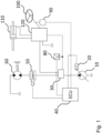
- a first embodiment of the hydraulic system according to the invention is shown as a schematic circuit diagram.
- the hydraulic system can be part of an auxiliary consumer circuit of a work machine such as a hydraulic excavator, via which several auxiliary consumers are supplied with hydraulic oil.
- the hydraulic system according to the invention provides several pressure-controlled and quantity-controlled hydraulic consumers, which are supplied via a single adjustable hydraulic pump 10.
- the hydraulic pump 10 can be, for example, an axial piston pump.
- the second valve block 120 is connected to a second output of the first valve block 30 via a supply line.
- the two valve blocks 30, 120 are connected to one another via a hydraulic control line, the pressure of which is detected by a first pressure sensor 80.
- the control line can be an LS signal line.
- the second valve block 120 is part of a hydraulic steering device, which also comprises one or more hydraulic steering cylinders 110.
- the steering cylinder(s) 110 ensure a deflection of steered wheels of the implement (not shown) when one of the pressure chambers is pressurized accordingly.
- the steering device further comprises a steering wheel 100 with a steering linkage, which is coupled to the second valve block 120 in such a way that a certain deflection of the steering wheel 100 leads to a certain adjustment of the steering cylinder(s) 110 and thus to a certain deflection of the wheels.
- a speed sensor 90 is connected to the steering linkage and detects an angle and/or an angular velocity and thus the steering speed.
- the steering cylinder(s) 110 represent the hydraulic consumer in the narrower sense, whereby for the sake of simplicity the entire steering device is referred to below as the hydraulic consumer.
- the steering device is a quantity-controlled consumer which requires a certain volume flow from the hydraulic pump 10.
- a pressure-controlled consumer 60 is provided, which in this embodiment is a hydraulic fan motor 60 for driving a ventilation system of the implement.
- the hydraulic pump 10 can be adjusted via an adjusting means 20 in the form of a pump regulator in order to deliver a specific volume flow and pressure.
- the adjusting means 20 can be a pressure regulator and/or swivel angle regulator.
- the hydraulic pump 10 is regulated via the pump regulator 20 in such a way that the fan motor 60 can be operated at the required pressure and the steering device can be provided with the required volume flow at the same time.
- the hydraulic pump 10 is not controlled by an LS control or a combination of several LS, pressure and, if applicable, power controllers, but rather by an electrical control arrangement.
- An electro-hydraulic displacement unit is thus used to supply all consumers of the hydraulic system.
- the control arrangement comprises an electronic control unit (ECU) 40, which is connected to the various sensors 80, 90 and receives and processes their signals. From the pressure measured by the first pressure sensor 80 in the control line between the valve blocks 30, 120 and the signals from the speed sensor 90, the control unit 40 calculates a volume flow required by the steering device and generates a control signal for the pump controller 20, to which the control unit 40 is electrically connected. The control unit 40 therefore gives the controller 20 a corresponding target value, whereupon the latter controls the hydraulic pump 20 in such a way that it delivers the requested volume flow.
- ECU electronice control unit
- the valve block 30 can be designed as a so-called priority valve, which in a first switching position only connects the pump outlet with the steering device and in a second switching position, it connects in parallel with the steering device and with the fan motor 60.
- the steering device is supplied, since its function is essential for the operation of the implement.
- the fan motor 60 must be operated at a certain pressure (which corresponds to a certain speed requirement for the fan), i.e. it is pressure-controlled.
- a third valve unit in the form of an electrically controllable pressure reducing valve 50 is connected between the fan motor 60 and the first outlet of the first valve block 30, the control input of which is electrically connected to the control unit 40.
- the control unit 40 controls the limit pressure of the pressure reducing valve 50, for example based on a specification for operating the ventilation system or a speed requirement. As long as the pressure at the first outlet of the first valve block 30 is greater than the limit pressure of the pressure reducing valve 50 set by the control unit 40, the same pressure is always applied to the fan motor 60.
- the pressure requirement is in turn made available to the pump controller 20 as a setpoint specification by the control unit 40.
- the hydraulic motor 10 is in particular controlled such that the pressure provided is greater than or equal to the limit pressure of the pressure reducing valve 50.
- the pressure-controlled consumer can generally be a hydraulic motor (such as the fan motor 60 of the embodiment shown here), a valve block or any other pressure-controlled consumer.
- several pressure-controlled consumers can be connected in parallel to one another to the first valve block 30.
- Such an embodiment is shown in Figure 2, wherein in addition to the fan motor 60, two further pressure-controlled consumers 140, 170 are provided and connected in parallel to the fan motor 60 to the first outlet of the first valve block 30.
- a hydraulic pilot control 140 is provided as an additional pressure-controlled consumer, which is directly connected to the first output of the first valve block 30.
- a hydraulic pressure reducing valve 130 can be connected upstream of the pilot control 140.
- the pilot control 140 can comprise or represent a control oil unit, which provides a specific control pressure (e.g. 30 bar) for other components of the hydraulic system (e.g. for a main consumer circuit).
- a hydraulic braking device 170 is provided as a further pressure-controlled consumer, which is connected parallel to the other pressure-controlled consumers 60, 140 directly to the first output of the first valve block 30.
- the braking device 170 can comprise a brake valve (for example a dual-circuit brake valve) with a brake pedal.
- the braking device is supplied with pressure via a hydraulic accumulator 150.
- the pressure in the accumulator 150 is continuously monitored for the current fill level by a second pressure sensor 160 that is electrically connected to the control unit 40, and the signals are made available to the control unit 40. If the pressure in the hydraulic accumulator 150 falls below a defined limit value (this can be stored in the control unit or in a memory connected to it), the control unit 40 sends the pump controller 20 a corresponding signal to swing out the hydraulic pump 10 in order to charge the hydraulic accumulator 150. The charging process continues until the hydraulic accumulator 150 is full.
- the pressure requirement for the hydraulic accumulator 150 is higher than the pressure requirement for the fan motor 60, the pressure is reduced accordingly by the pressure reducing valve 50.
- the second valve block 120 preferably regulates the excess pressure independently (similar to a pressure compensator).
- the hydraulic pump 10 can be set to completely torque-free during the start-up process. This reduces the torque when starting the machine, which makes the start-up process much easier.
- the control arrangement supplies the various auxiliary consumers with the required amount of oil as needed via a single adjustable hydraulic pump.
- the Figure 3 shows the embodiment of the hydraulic system of the Figure 2 in a more detailed view.
- the dual-circuit brake valve 170 which connects two individual hydraulic accumulators 150 to the hydraulic brakes.
- a check valve is connected between the brake valve 170 and the hydraulic accumulators 150 on the one hand and the first valve block 30 on the other hand and blocks a hydraulic return flow from the accumulator 150 to the first valve block 30.
- the priority valve 30 can be seen with its two switching positions (first, in the Figure 3 lower switch position: sole supply of the steering device; second, in the Figure 3 upper switching position: parallel supply of the steering device and the other pressure-controlled consumers).
- the structure of the steering valve or the second valve block 120 can also be seen.
- the priority valve 30 is not controlled via the control unit 40, but hydraulically via the control line connected to the second valve block 120.
- a third embodiment of the hydraulic system according to the invention is shown as a schematic circuit diagram.
- the only difference compared to the embodiment of the Figure 1 is that no first valve block 30 (first valve unit) is provided. Instead, the pressure reducing valve 50 and the second valve block 120 (second valve unit) are connected directly to the hydraulic pump 10.
- the pressure sensor 80 detects the pressure in a hydraulic line of the second valve block 120, which can be, for example, a hydraulic control line of the second valve block 120.
- a hydraulic line of the second valve block 120 can be, for example, a hydraulic control line of the second valve block 120.
Landscapes
- Engineering & Computer Science (AREA)
- General Engineering & Computer Science (AREA)
- Mining & Mineral Resources (AREA)
- Civil Engineering (AREA)
- Structural Engineering (AREA)
- Physics & Mathematics (AREA)
- Fluid Mechanics (AREA)
- Mechanical Engineering (AREA)
- Fluid-Pressure Circuits (AREA)
Claims (15)
- Système hydraulique comprenant au moins deux consommateurs hydrauliques dont au moins un consommateur est à régulation de pression et au moins un consommateur est à régulation de débit, une pompe hydraulique (10) réglable, par le biais de laquelle les au moins deux consommateurs sont alimentés conjointement, et un ensemble de régulation,
caractérisé en ce que
la pompe hydraulique (10) est régulée électriquement au moyen de l'ensemble de régulation, l'ensemble de régulation comprenant un appareil de commande (40) et un système de capteurs relié à l'appareil de commande (40) pour détecter au moins une grandeur caractérisant un besoin d'un consommateur, l'appareil de commande (40) étant configuré pour, en utilisant l'au moins une grandeur détectée, déterminer une pression requise par un consommateur à régulation de pression ainsi qu'un débit volumétrique requis par un consommateur à régulation de débit et réguler la pompe hydraulique (10) de telle manière que la pression requise et le débit volumétrique requis sont fournis. - Système hydraulique selon la revendication 1, comprenant en outre une deuxième unité de soupapes (120) qui est montée entre la pompe hydraulique (10) et au moins un consommateur à régulation de débit et qui n'est de préférence pas commandée électriquement par l'appareil de commande (40).
- Système hydraulique selon la revendication précédente, dans lequel le système de capteurs comprend un capteur de pression (80) qui détecte une pression dans la deuxième unité de soupapes (120), en particulier dans une ligne de commande de la deuxième unité de soupapes (120).
- Système hydraulique selon l'une des revendications précédentes, comprenant en outre une première unité de soupapes (30) qui relie les au moins deux consommateurs à la pompe hydraulique (10) et qui n'est de préférence pas commandée électriquement par l'appareil de commande (40).
- Système hydraulique selon la revendication 4 et l'une des revendications 2 à 3, dans lequel la deuxième unité de soupapes (120) est montée entre la première unité de soupapes (30) et au moins un consommateur à régulation de débit, la première unité de soupapes (30) étant de préférence reliée à la deuxième unité de soupapes (120) par le biais d'une ligne de commande hydraulique et le système de capteurs comprenant en particulier un capteur de pression (80) qui détecte une pression dans la ligne de commande entre la première et la deuxième unité de soupapes (30, 120).
- Système hydraulique selon l'une des deux revendications précédentes, dans lequel la première unité de soupapes (30) est configurée pour alimenter au moins un consommateur (110), en particulier à régulation de débit, en huile hydraulique de manière prioritaire par rapport à au moins un autre consommateur (60, 140, 170), en particulier à régulation de pression.
- Système hydraulique selon la revendication précédente, dans lequel la première unité de soupapes (30) comprend une soupape de priorité commutable qui, de préférence, alimente, dans une première position de commutation, exclusivement un ou plusieurs consommateurs (110) à régulation de débit et, dans une deuxième position de commutation, parallèlement l'au moins un consommateur (110) à régulation de débit et un ou plusieurs consommateurs (60, 140, 170) à régulation de pression.
- Système hydraulique selon l'une des revendications précédentes, dans lequel au moins un consommateur (110) à régulation de débit fait partie d'un dispositif de direction hydraulique (100, 110, 120), le système de capteurs comprenant de préférence un capteur de vitesse de rotation (90) couplé au dispositif de direction (100, 110, 120) pour détecter une vitesse de changement de direction.
- Système hydraulique selon l'une des revendications précédentes, dans lequel l'ensemble de régulation comprend un moyen de réglage (20) destiné au réglage d'une pression et/ou d'un angle de pivotement de la pompe hydraulique (10), ledit moyen de réglage étant relié électriquement à l'appareil de commande (40).
- Système hydraulique selon l'une des revendications précédentes, dans lequel au moins un consommateur (60) à régulation de pression est relié à la pompe hydraulique (10) par le biais d'une troisième unité de soupapes (50), la troisième unité de soupapes (50) pouvant de préférence être commandée électriquement par l'appareil de commande (40) par le biais d'une ligne de commande électrique.
- Système hydraulique selon l'une des revendications précédentes, dans lequel au moins un consommateur (170) à régulation de pression peut être alimenté par le biais d'un accumulateur hydraulique (150), l'accumulateur hydraulique (150) pouvant de préférence être chargé par le biais de la pompe hydraulique (10), un consommateur relié à l'accumulateur hydraulique (150) étant en particulier un dispositif de freinage hydraulique (170).
- Système hydraulique selon la revendication précédente, dans lequel le système de capteurs comprend un capteur de pression (160) qui détecte une pression régnant dans l'accumulateur hydraulique (150), l'ensemble de régulation étant de préférence configuré pour réguler la pompe hydraulique (10) en fonction d'un signal du capteur de pression (160) de telle manière que l'accumulateur hydraulique (150) est rempli.
- Système hydraulique selon l'une des revendications précédentes, dans lequel, en guise de consommateur à régulation de pression, il est prévu un moteur hydraulique (60) pour une unité de ventilation et/ou une commande pilote hydraulique (140), en amont de laquelle une soupape réductrice de pression (130) et/ou une soupape de décompression (50) est de préférence placée.
- Système hydraulique selon l'une des revendications précédentes, dans lequel aucune autre pompe que la pompe hydraulique (10) n'est prévue pour l'alimentation des consommateurs.
- Engin de chantier, en particulier pelle hydraulique, comportant un système hydraulique selon l'une des revendications précédentes, le système hydraulique faisant de préférence partie d'un circuit de consommateurs auxiliaires de l'engin de chantier.
Applications Claiming Priority (1)
| Application Number | Priority Date | Filing Date | Title |
|---|---|---|---|
| DE102022113799.6A DE102022113799A1 (de) | 2022-06-01 | 2022-06-01 | Hydrauliksystem und Arbeitsgerät mit einem solchen |
Publications (2)
| Publication Number | Publication Date |
|---|---|
| EP4286607A1 EP4286607A1 (fr) | 2023-12-06 |
| EP4286607B1 true EP4286607B1 (fr) | 2024-12-25 |
Family
ID=85410430
Family Applications (1)
| Application Number | Title | Priority Date | Filing Date |
|---|---|---|---|
| EP23159071.2A Active EP4286607B1 (fr) | 2022-06-01 | 2023-02-28 | Système hydraulique et engin de chantier équipé d'un tel système hydraulique |
Country Status (2)
| Country | Link |
|---|---|
| EP (1) | EP4286607B1 (fr) |
| DE (1) | DE102022113799A1 (fr) |
Family Cites Families (8)
| Publication number | Priority date | Publication date | Assignee | Title |
|---|---|---|---|---|
| DE19531413B4 (de) | 1995-08-26 | 2007-09-20 | Bosch Rexroth Aktiengesellschaft | Anordnung zur Versorgung der hydraulischen Lenkung eines Kraftfahrzeugs |
| US6314729B1 (en) | 1998-07-23 | 2001-11-13 | Sauer-Danfoss Inc. | Hydraulic fan drive system having a non-dedicated flow source |
| US6848255B2 (en) | 2002-12-18 | 2005-02-01 | Caterpillar Inc | Hydraulic fan drive system |
| DE102005022089B4 (de) | 2005-05-12 | 2019-11-07 | Linde Material Handling Gmbh | Hydraulische Lenkeinrichtung |
| DE102015111926A1 (de) | 2015-07-22 | 2017-01-26 | Linde Material Handling Gmbh | Mobile Arbeitsmaschine, insbesondere Flurförderzeug, mit einem elektrischen Antriebssystem |
| DE102016000186A1 (de) | 2016-01-11 | 2017-07-13 | Liebherr-Hydraulikbagger Gmbh | Vorrichtung zur regelbaren Hydraulikversorgung unterschiedlich geregelter hydraulischer Verbraucher sowie Hydrauliksystem und Arbeitsmaschine |
| JP6473702B2 (ja) | 2016-02-01 | 2019-02-20 | 株式会社Kcm | 作業機械 |
| JP7257132B2 (ja) * | 2018-11-15 | 2023-04-13 | 株式会社小松製作所 | 作業機械 |
-
2022
- 2022-06-01 DE DE102022113799.6A patent/DE102022113799A1/de active Pending
-
2023
- 2023-02-28 EP EP23159071.2A patent/EP4286607B1/fr active Active
Also Published As
| Publication number | Publication date |
|---|---|
| EP4286607A1 (fr) | 2023-12-06 |
| DE102022113799A1 (de) | 2023-12-07 |
Similar Documents
| Publication | Publication Date | Title |
|---|---|---|
| DE112010001958B4 (de) | Steuervorrichtung für eine hybride Baumaschine | |
| DE112008000818B4 (de) | Verfahren zur Steuerung einer Hybridbaumaschine und Hybridbaumaschine | |
| DE69705548T2 (de) | Hydraulisches Betätigungssystem für Baumaschinen | |
| DE19839062C2 (de) | Hydraulische Maschinensteuerung | |
| EP2050961B1 (fr) | Système d'entraînement hydraulique | |
| DE10010670C2 (de) | Hydraulische Hubvorrichtung für batteriebetriebene Flurförderzeuge | |
| DE102019110711B4 (de) | Ansteuerverfahren für ein Hydrauliksystem mit einer Pumpe und Ventilen zum Versorgen mehrerer Verbraucher sowie einer Kühl- und/oder Schmiereinrichtung; und Hydrauliksystem | |
| DE102009021866A1 (de) | Hydroantrieb mit einer unabhängigen Speisepumpe | |
| DE102013213302A1 (de) | Steuersystem sowie Verfahren zum Betreiben eines Kraftfahrzeugs | |
| DE3441185A1 (de) | Antriebssystem | |
| DE102019110710B3 (de) | Ansteuerverfahren für ein Hydrauliksystem mit einer Pumpe und mehreren Ventilen; sowie Hydrauliksystem | |
| DE102014105127A1 (de) | Hydraulisches Antriebssystem einer mobilen Arbeitsmaschine | |
| EP3249241B1 (fr) | Procédé de détermination de la position finale d'un vérin hydraulique d'un système hydraulique d'une machine de travail mobile, en particulier un chariot de manutention | |
| DE2056967A1 (de) | Blockierregelbremssystem fur Fahr zeuge | |
| WO1992010685A1 (fr) | Systeme hydraulique | |
| WO2023241843A1 (fr) | Alimentation en flux volumique | |
| DE112015005464T5 (de) | Steuersystem für eine Hybridbaumaschine | |
| DE3528096C2 (fr) | ||
| EP4286607B1 (fr) | Système hydraulique et engin de chantier équipé d'un tel système hydraulique | |
| DE102017213118A1 (de) | Ventilblockanordnung und Verfahren für eine Ventilblockanordnung | |
| DE102017109421A1 (de) | Hydrauliksystem einer land- oder bauwirtschaftlich nutzbaren Arbeitsmaschine | |
| DE102007051525B4 (de) | Hydraulisches Versorgungssystem mit einer Verstellpumpeneinrichtung | |
| DE3911531A1 (de) | Hydraulik-system fuer kraftfahrzeuge | |
| DE102016201588A1 (de) | Verfahren zur Einstellung eines hydrostatischen Fahrantriebs | |
| DE102021210117A1 (de) | Verfahren für einen hydraulischen Antrieb, Steuereinheit, Computerprogramm, und maschinenlesbares Speichermedium |
Legal Events
| Date | Code | Title | Description |
|---|---|---|---|
| PUAI | Public reference made under article 153(3) epc to a published international application that has entered the european phase |
Free format text: ORIGINAL CODE: 0009012 |
|
| STAA | Information on the status of an ep patent application or granted ep patent |
Free format text: STATUS: THE APPLICATION HAS BEEN PUBLISHED |
|
| AK | Designated contracting states |
Kind code of ref document: A1 Designated state(s): AL AT BE BG CH CY CZ DE DK EE ES FI FR GB GR HR HU IE IS IT LI LT LU LV MC ME MK MT NL NO PL PT RO RS SE SI SK SM TR |
|
| STAA | Information on the status of an ep patent application or granted ep patent |
Free format text: STATUS: REQUEST FOR EXAMINATION WAS MADE |
|
| 17P | Request for examination filed |
Effective date: 20240425 |
|
| GRAP | Despatch of communication of intention to grant a patent |
Free format text: ORIGINAL CODE: EPIDOSNIGR1 |
|
| STAA | Information on the status of an ep patent application or granted ep patent |
Free format text: STATUS: GRANT OF PATENT IS INTENDED |
|
| RIC1 | Information provided on ipc code assigned before grant |
Ipc: F15B 11/16 20060101ALI20240729BHEP Ipc: E02F 9/22 20060101AFI20240729BHEP |
|
| INTG | Intention to grant announced |
Effective date: 20240816 |
|
| GRAS | Grant fee paid |
Free format text: ORIGINAL CODE: EPIDOSNIGR3 |
|
| GRAA | (expected) grant |
Free format text: ORIGINAL CODE: 0009210 |
|
| STAA | Information on the status of an ep patent application or granted ep patent |
Free format text: STATUS: THE PATENT HAS BEEN GRANTED |
|
| AK | Designated contracting states |
Kind code of ref document: B1 Designated state(s): AL AT BE BG CH CY CZ DE DK EE ES FI FR GB GR HR HU IE IS IT LI LT LU LV MC ME MK MT NL NO PL PT RO RS SE SI SK SM TR |
|
| REG | Reference to a national code |
Ref country code: GB Ref legal event code: FG4D Free format text: NOT ENGLISH |
|
| REG | Reference to a national code |
Ref country code: CH Ref legal event code: EP |
|
| REG | Reference to a national code |
Ref country code: DE Ref legal event code: R096 Ref document number: 502023000414 Country of ref document: DE |
|
| REG | Reference to a national code |
Ref country code: IE Ref legal event code: FG4D Free format text: LANGUAGE OF EP DOCUMENT: GERMAN |
|
| REG | Reference to a national code |
Ref country code: LT Ref legal event code: MG9D |
|
| PG25 | Lapsed in a contracting state [announced via postgrant information from national office to epo] |
Ref country code: HR Free format text: LAPSE BECAUSE OF FAILURE TO SUBMIT A TRANSLATION OF THE DESCRIPTION OR TO PAY THE FEE WITHIN THE PRESCRIBED TIME-LIMIT Effective date: 20241225 |
|
| PG25 | Lapsed in a contracting state [announced via postgrant information from national office to epo] |
Ref country code: FI Free format text: LAPSE BECAUSE OF FAILURE TO SUBMIT A TRANSLATION OF THE DESCRIPTION OR TO PAY THE FEE WITHIN THE PRESCRIBED TIME-LIMIT Effective date: 20241225 |
|
| PG25 | Lapsed in a contracting state [announced via postgrant information from national office to epo] |
Ref country code: BG Free format text: LAPSE BECAUSE OF FAILURE TO SUBMIT A TRANSLATION OF THE DESCRIPTION OR TO PAY THE FEE WITHIN THE PRESCRIBED TIME-LIMIT Effective date: 20241225 |
|
| PG25 | Lapsed in a contracting state [announced via postgrant information from national office to epo] |
Ref country code: NO Free format text: LAPSE BECAUSE OF FAILURE TO SUBMIT A TRANSLATION OF THE DESCRIPTION OR TO PAY THE FEE WITHIN THE PRESCRIBED TIME-LIMIT Effective date: 20250325 |
|
| PG25 | Lapsed in a contracting state [announced via postgrant information from national office to epo] |
Ref country code: LV Free format text: LAPSE BECAUSE OF FAILURE TO SUBMIT A TRANSLATION OF THE DESCRIPTION OR TO PAY THE FEE WITHIN THE PRESCRIBED TIME-LIMIT Effective date: 20241225 Ref country code: GR Free format text: LAPSE BECAUSE OF FAILURE TO SUBMIT A TRANSLATION OF THE DESCRIPTION OR TO PAY THE FEE WITHIN THE PRESCRIBED TIME-LIMIT Effective date: 20250326 |
|
| PG25 | Lapsed in a contracting state [announced via postgrant information from national office to epo] |
Ref country code: RS Free format text: LAPSE BECAUSE OF FAILURE TO SUBMIT A TRANSLATION OF THE DESCRIPTION OR TO PAY THE FEE WITHIN THE PRESCRIBED TIME-LIMIT Effective date: 20250325 |
|
| REG | Reference to a national code |
Ref country code: NL Ref legal event code: MP Effective date: 20241225 |
|
| PG25 | Lapsed in a contracting state [announced via postgrant information from national office to epo] |
Ref country code: NL Free format text: LAPSE BECAUSE OF FAILURE TO SUBMIT A TRANSLATION OF THE DESCRIPTION OR TO PAY THE FEE WITHIN THE PRESCRIBED TIME-LIMIT Effective date: 20241225 |
|
| PG25 | Lapsed in a contracting state [announced via postgrant information from national office to epo] |
Ref country code: SM Free format text: LAPSE BECAUSE OF FAILURE TO SUBMIT A TRANSLATION OF THE DESCRIPTION OR TO PAY THE FEE WITHIN THE PRESCRIBED TIME-LIMIT Effective date: 20241225 |
|
| PG25 | Lapsed in a contracting state [announced via postgrant information from national office to epo] |
Ref country code: PL Free format text: LAPSE BECAUSE OF FAILURE TO SUBMIT A TRANSLATION OF THE DESCRIPTION OR TO PAY THE FEE WITHIN THE PRESCRIBED TIME-LIMIT Effective date: 20241225 |
|
| PG25 | Lapsed in a contracting state [announced via postgrant information from national office to epo] |
Ref country code: ES Free format text: LAPSE BECAUSE OF FAILURE TO SUBMIT A TRANSLATION OF THE DESCRIPTION OR TO PAY THE FEE WITHIN THE PRESCRIBED TIME-LIMIT Effective date: 20241225 |
|
| PG25 | Lapsed in a contracting state [announced via postgrant information from national office to epo] |
Ref country code: IS Free format text: LAPSE BECAUSE OF FAILURE TO SUBMIT A TRANSLATION OF THE DESCRIPTION OR TO PAY THE FEE WITHIN THE PRESCRIBED TIME-LIMIT Effective date: 20250425 |
|
| PG25 | Lapsed in a contracting state [announced via postgrant information from national office to epo] |
Ref country code: PT Free format text: LAPSE BECAUSE OF FAILURE TO SUBMIT A TRANSLATION OF THE DESCRIPTION OR TO PAY THE FEE WITHIN THE PRESCRIBED TIME-LIMIT Effective date: 20250428 |
|
| PG25 | Lapsed in a contracting state [announced via postgrant information from national office to epo] |
Ref country code: EE Free format text: LAPSE BECAUSE OF FAILURE TO SUBMIT A TRANSLATION OF THE DESCRIPTION OR TO PAY THE FEE WITHIN THE PRESCRIBED TIME-LIMIT Effective date: 20241225 |
|
| PG25 | Lapsed in a contracting state [announced via postgrant information from national office to epo] |
Ref country code: RO Free format text: LAPSE BECAUSE OF FAILURE TO SUBMIT A TRANSLATION OF THE DESCRIPTION OR TO PAY THE FEE WITHIN THE PRESCRIBED TIME-LIMIT Effective date: 20241225 |
|
| PG25 | Lapsed in a contracting state [announced via postgrant information from national office to epo] |
Ref country code: SK Free format text: LAPSE BECAUSE OF FAILURE TO SUBMIT A TRANSLATION OF THE DESCRIPTION OR TO PAY THE FEE WITHIN THE PRESCRIBED TIME-LIMIT Effective date: 20241225 |
|
| PG25 | Lapsed in a contracting state [announced via postgrant information from national office to epo] |
Ref country code: CZ Free format text: LAPSE BECAUSE OF FAILURE TO SUBMIT A TRANSLATION OF THE DESCRIPTION OR TO PAY THE FEE WITHIN THE PRESCRIBED TIME-LIMIT Effective date: 20241225 |
|
| PG25 | Lapsed in a contracting state [announced via postgrant information from national office to epo] |
Ref country code: SE Free format text: LAPSE BECAUSE OF FAILURE TO SUBMIT A TRANSLATION OF THE DESCRIPTION OR TO PAY THE FEE WITHIN THE PRESCRIBED TIME-LIMIT Effective date: 20241225 |
|
| PG25 | Lapsed in a contracting state [announced via postgrant information from national office to epo] |
Ref country code: MC Free format text: LAPSE BECAUSE OF FAILURE TO SUBMIT A TRANSLATION OF THE DESCRIPTION OR TO PAY THE FEE WITHIN THE PRESCRIBED TIME-LIMIT Effective date: 20241225 |
|
| REG | Reference to a national code |
Ref country code: DE Ref legal event code: R097 Ref document number: 502023000414 Country of ref document: DE |
|
| PG25 | Lapsed in a contracting state [announced via postgrant information from national office to epo] |
Ref country code: DK Free format text: LAPSE BECAUSE OF FAILURE TO SUBMIT A TRANSLATION OF THE DESCRIPTION OR TO PAY THE FEE WITHIN THE PRESCRIBED TIME-LIMIT Effective date: 20241225 |
|
| PG25 | Lapsed in a contracting state [announced via postgrant information from national office to epo] |
Ref country code: LU Free format text: LAPSE BECAUSE OF NON-PAYMENT OF DUE FEES Effective date: 20250228 |
|
| PLBE | No opposition filed within time limit |
Free format text: ORIGINAL CODE: 0009261 |
|
| STAA | Information on the status of an ep patent application or granted ep patent |
Free format text: STATUS: NO OPPOSITION FILED WITHIN TIME LIMIT |
|
| 26N | No opposition filed |
Effective date: 20250926 |
|
| PG25 | Lapsed in a contracting state [announced via postgrant information from national office to epo] |
Ref country code: IE Free format text: LAPSE BECAUSE OF NON-PAYMENT OF DUE FEES Effective date: 20250228 |
|
| PGFP | Annual fee paid to national office [announced via postgrant information from national office to epo] |
Ref country code: DE Payment date: 20260303 Year of fee payment: 4 |
|
| PGFP | Annual fee paid to national office [announced via postgrant information from national office to epo] |
Ref country code: AT Payment date: 20260301 Year of fee payment: 4 |
|
| PGFP | Annual fee paid to national office [announced via postgrant information from national office to epo] |
Ref country code: BE Payment date: 20260225 Year of fee payment: 4 Ref country code: IT Payment date: 20260228 Year of fee payment: 4 |
|
| PGFP | Annual fee paid to national office [announced via postgrant information from national office to epo] |
Ref country code: FR Payment date: 20260225 Year of fee payment: 4 |