EP4287486A1 - Verfahren zur festlegung einer ausgangsleistungsgrenze eines frequenzumrichters und verfahren zur diagnose des zustandes von zwischenkreiskondensatoren - Google Patents
Verfahren zur festlegung einer ausgangsleistungsgrenze eines frequenzumrichters und verfahren zur diagnose des zustandes von zwischenkreiskondensatoren Download PDFInfo
- Publication number
- EP4287486A1 EP4287486A1 EP22176628.0A EP22176628A EP4287486A1 EP 4287486 A1 EP4287486 A1 EP 4287486A1 EP 22176628 A EP22176628 A EP 22176628A EP 4287486 A1 EP4287486 A1 EP 4287486A1
- Authority
- EP
- European Patent Office
- Prior art keywords
- frequency converter
- capacitors
- output power
- computer
- power limit
- Prior art date
- Legal status (The legal status is an assumption and is not a legal conclusion. Google has not performed a legal analysis and makes no representation as to the accuracy of the status listed.)
- Granted
Links
Images


Classifications
-
- H—ELECTRICITY
- H02—GENERATION; CONVERSION OR DISTRIBUTION OF ELECTRIC POWER
- H02P—CONTROL OR REGULATION OF ELECTRIC MOTORS, ELECTRIC GENERATORS OR DYNAMO-ELECTRIC CONVERTERS; CONTROLLING TRANSFORMERS, REACTORS OR CHOKE COILS
- H02P27/00—Arrangements or methods for the control of AC motors characterised by the kind of supply voltage
- H02P27/04—Arrangements or methods for the control of AC motors characterised by the kind of supply voltage using variable-frequency supply voltage, e.g. inverter or converter supply voltage
-
- H—ELECTRICITY
- H02—GENERATION; CONVERSION OR DISTRIBUTION OF ELECTRIC POWER
- H02M—APPARATUS FOR CONVERSION BETWEEN AC AND AC, BETWEEN AC AND DC, OR BETWEEN DC AND DC, AND FOR USE WITH MAINS OR SIMILAR POWER SUPPLY SYSTEMS; CONVERSION OF DC OR AC INPUT POWER INTO SURGE OUTPUT POWER; CONTROL OR REGULATION THEREOF
- H02M7/00—Conversion of AC power input into DC power output; Conversion of DC power input into AC power output
- H02M7/42—Conversion of DC power input into AC power output without possibility of reversal
- H02M7/44—Conversion of DC power input into AC power output without possibility of reversal by static converters
- H02M7/48—Conversion of DC power input into AC power output without possibility of reversal by static converters using discharge tubes with control electrode or semiconductor devices with control electrode
- H02M7/53—Conversion of DC power input into AC power output without possibility of reversal by static converters using discharge tubes with control electrode or semiconductor devices with control electrode using devices of a triode or transistor type requiring continuous application of a control signal
- H02M7/537—Conversion of DC power input into AC power output without possibility of reversal by static converters using discharge tubes with control electrode or semiconductor devices with control electrode using devices of a triode or transistor type requiring continuous application of a control signal using semiconductor devices only, e.g. single switched pulse inverters
- H02M7/5387—Conversion of DC power input into AC power output without possibility of reversal by static converters using discharge tubes with control electrode or semiconductor devices with control electrode using devices of a triode or transistor type requiring continuous application of a control signal using semiconductor devices only, e.g. single switched pulse inverters in a bridge configuration
- H02M7/53871—Conversion of DC power input into AC power output without possibility of reversal by static converters using discharge tubes with control electrode or semiconductor devices with control electrode using devices of a triode or transistor type requiring continuous application of a control signal using semiconductor devices only, e.g. single switched pulse inverters in a bridge configuration with automatic control of output voltage or current
-
- H—ELECTRICITY
- H02—GENERATION; CONVERSION OR DISTRIBUTION OF ELECTRIC POWER
- H02M—APPARATUS FOR CONVERSION BETWEEN AC AND AC, BETWEEN AC AND DC, OR BETWEEN DC AND DC, AND FOR USE WITH MAINS OR SIMILAR POWER SUPPLY SYSTEMS; CONVERSION OF DC OR AC INPUT POWER INTO SURGE OUTPUT POWER; CONTROL OR REGULATION THEREOF
- H02M5/00—Conversion of AC power input into AC power output, e.g. for change of voltage, for change of frequency, for change of number of phases
- H02M5/40—Conversion of AC power input into AC power output, e.g. for change of voltage, for change of frequency, for change of number of phases with intermediate conversion into DC
- H02M5/42—Conversion of AC power input into AC power output, e.g. for change of voltage, for change of frequency, for change of number of phases with intermediate conversion into DC by static converters
- H02M5/44—Conversion of AC power input into AC power output, e.g. for change of voltage, for change of frequency, for change of number of phases with intermediate conversion into DC by static converters using discharge tubes or semiconductor devices to convert the intermediate DC into AC
- H02M5/453—Conversion of AC power input into AC power output, e.g. for change of voltage, for change of frequency, for change of number of phases with intermediate conversion into DC by static converters using discharge tubes or semiconductor devices to convert the intermediate DC into AC using devices of a triode or transistor type requiring continuous application of a control signal
- H02M5/458—Conversion of AC power input into AC power output, e.g. for change of voltage, for change of frequency, for change of number of phases with intermediate conversion into DC by static converters using discharge tubes or semiconductor devices to convert the intermediate DC into AC using devices of a triode or transistor type requiring continuous application of a control signal using semiconductor devices only
-
- H—ELECTRICITY
- H02—GENERATION; CONVERSION OR DISTRIBUTION OF ELECTRIC POWER
- H02M—APPARATUS FOR CONVERSION BETWEEN AC AND AC, BETWEEN AC AND DC, OR BETWEEN DC AND DC, AND FOR USE WITH MAINS OR SIMILAR POWER SUPPLY SYSTEMS; CONVERSION OF DC OR AC INPUT POWER INTO SURGE OUTPUT POWER; CONTROL OR REGULATION THEREOF
- H02M1/00—Details of apparatus for conversion
- H02M1/32—Means for protecting converters other than automatic disconnection
-
- H—ELECTRICITY
- H02—GENERATION; CONVERSION OR DISTRIBUTION OF ELECTRIC POWER
- H02P—CONTROL OR REGULATION OF ELECTRIC MOTORS, ELECTRIC GENERATORS OR DYNAMO-ELECTRIC CONVERTERS; CONTROLLING TRANSFORMERS, REACTORS OR CHOKE COILS
- H02P27/00—Arrangements or methods for the control of AC motors characterised by the kind of supply voltage
- H02P27/04—Arrangements or methods for the control of AC motors characterised by the kind of supply voltage using variable-frequency supply voltage, e.g. inverter or converter supply voltage
- H02P27/06—Arrangements or methods for the control of AC motors characterised by the kind of supply voltage using variable-frequency supply voltage, e.g. inverter or converter supply voltage using DC to AC converters or inverters
-
- G—PHYSICS
- G01—MEASURING; TESTING
- G01R—MEASURING ELECTRIC VARIABLES; MEASURING MAGNETIC VARIABLES
- G01R31/00—Arrangements for testing electric properties; Arrangements for locating electric faults; Arrangements for electrical testing characterised by what is being tested not provided for elsewhere
-
- H—ELECTRICITY
- H02—GENERATION; CONVERSION OR DISTRIBUTION OF ELECTRIC POWER
- H02M—APPARATUS FOR CONVERSION BETWEEN AC AND AC, BETWEEN AC AND DC, OR BETWEEN DC AND DC, AND FOR USE WITH MAINS OR SIMILAR POWER SUPPLY SYSTEMS; CONVERSION OF DC OR AC INPUT POWER INTO SURGE OUTPUT POWER; CONTROL OR REGULATION THEREOF
- H02M1/00—Details of apparatus for conversion
- H02M1/14—Arrangements for reducing ripples from DC input or output
- H02M1/15—Arrangements for reducing ripples from DC input or output using active elements
-
- H—ELECTRICITY
- H02—GENERATION; CONVERSION OR DISTRIBUTION OF ELECTRIC POWER
- H02M—APPARATUS FOR CONVERSION BETWEEN AC AND AC, BETWEEN AC AND DC, OR BETWEEN DC AND DC, AND FOR USE WITH MAINS OR SIMILAR POWER SUPPLY SYSTEMS; CONVERSION OF DC OR AC INPUT POWER INTO SURGE OUTPUT POWER; CONTROL OR REGULATION THEREOF
- H02M7/00—Conversion of AC power input into DC power output; Conversion of DC power input into AC power output
- H02M7/42—Conversion of DC power input into AC power output without possibility of reversal
- H02M7/44—Conversion of DC power input into AC power output without possibility of reversal by static converters
- H02M7/48—Conversion of DC power input into AC power output without possibility of reversal by static converters using discharge tubes with control electrode or semiconductor devices with control electrode
- H02M7/53—Conversion of DC power input into AC power output without possibility of reversal by static converters using discharge tubes with control electrode or semiconductor devices with control electrode using devices of a triode or transistor type requiring continuous application of a control signal
- H02M7/537—Conversion of DC power input into AC power output without possibility of reversal by static converters using discharge tubes with control electrode or semiconductor devices with control electrode using devices of a triode or transistor type requiring continuous application of a control signal using semiconductor devices only, e.g. single switched pulse inverters
- H02M7/539—Conversion of DC power input into AC power output without possibility of reversal by static converters using discharge tubes with control electrode or semiconductor devices with control electrode using devices of a triode or transistor type requiring continuous application of a control signal using semiconductor devices only, e.g. single switched pulse inverters with automatic control of output wave form or frequency
Definitions
- the present invention relates to a method for fixing an output power limit of a frequency converter and a method for diagnosing conditions of DC-link capacitors.
- frequency converters have a key role in a control of electric engines, for example electric engines used in power plants which have to run 24 hours per day and 7 days per week. They allow, in particular, adjusting speed of controlled electric engines to actual needs of their users. Operation of electric engines with adjusted speed leads to energy savings in comparison to operation of the electric engines with nominal speed. That's why it is important for installations equipped with frequency converters to provide reliable and uninterrupted operation of said frequency converters.
- a proper monitoring of frequency converters' components is essential since different kinds of frequency converters' components are designed to operate for different time periods. Moreover, different components have different modes of ageing. Among all the components used within said frequency converters, DC-link capacitors have the smallest resistance against an ageing process.
- the FIT parameter is following the bathtub curve, which comprises three periods: early failures when the FIT parameter is decreasing, random failures when the FIT parameter is constant, and wear out failures when the FIT parameter is increasing.
- DC-link capacitors are in random failures period. After using them for a time each of those capacitors enters a wear-out failure mode.
- the wear-out failure mode means that the electrical parameters of the capacitors gradually deteriorate and the capacitor fails. In said mode the FIT parameter is no longer valid what means that the capacitors will fail more often.
- said DC-link capacitors play a key role in ensuring uninterrupted and reliable operation of mentioned frequency converters so it is required to plan maintenance action and replacement of those capacitors more often than other components if necessary.
- a capacitor fault monitor for indicating a short circuit in a multi-section capacitor or a number of capacitors connected in series.
- Said capacitor fault monitor comprises a voltage divider, wherein the voltage divider comprises resistors connected in series. Said resistors are connected in parallel with said sections of the capacitor or the capacitors connected in series.
- the capacitor fault monitor is adopted to detect any voltage change across said capacitors to indicate a faulty capacitor.
- the object of the disclosed invention is to provide a simple relatively inexpensive and convenient means for determining a faulty capacitor in an electrical circuit.
- Another object of the invention is to detect short-circuit in a capacitor to prevent an explosion in the capacitor.
- the fault detector for detecting faults in a DC capacitor circuit connected to the DC buses of an inverter circuit using semiconductor device for converting direct current into alternating current to suppress the voltage pulsation.
- the fault detector comprises a plurality of parallel-connected capacitor circuits each having a plurality of series-connected DC capacitors, and comparison means connected to the junctions of the series-connected DC capacitors to compare the respective potentials of the parallel-connected capacitor circuits and detects the short-circuit and time-ageing of the DC capacitors of the parallel-connected capacitor circuits rapidly on the basis of the output signal of the comparison means.
- the aim of the disclosed solution is to provide a fault detector capable of instantaneous detection of the anomalous condition of a DC capacitor circuit, such as an internal short-circuit, and capable of detection of the deterioration of the DC capacitors in performance, attributable to time ageing.
- American patent US6211684 discloses a capacitor comprising a housing, a first plurality of capacitor sections in a first series within the housing, a second plurality of capacitor sections in a second series within the housing, a first electrode coupled to a first terminal of the first series and a first terminal of the second series, wherein the first electrode is electrically contactable outside the housing; and a second electrode coupled to a second terminal of the first series and a second terminal of the second series, wherein the second electrode is contactable outside the housing.
- the capacitor comprises further a voltage unbalance detection circuit containing a voltage detector and a threshold circuit.
- the voltage detector is interposed between a node of the first series of the capacitor sections and a node of the second series of the capacitors in order to measure a voltage between the nodes of two parallel series constituting two parallel current paths.
- the voltage detector provides an output signal to the threshold circuit.
- the threshold circuit is configured to generate an unbalance detection signal at the unbalance detection output as a function of the voltage indicated by the voltage detector.
- the signal output is configured to transmit an output signal to outside the housing.
- the aim of the disclosed solution is an early detection or a pre-detection of an incipient capacitor failure without shutdown of the capacitor, unless a catastrophic failure, such as an explosion, of the capacitor is imminent.
- the further aim of the mentioned solution is to enable capacitors with early detected minor faults to continue operation until repairs are scheduled without unnecessary interruptions.
- an object of the invention is to provide a method allowing assessment of the reliability of DC-link circuit capacitors and consequently prediction of duration of reliable operation of a frequency converter comprising such DC-link circuit capacitors, and further a method allowing operation of a frequency converter with ageing DC-link circuit capacitors without replacing such capacitors until the scheduled service date of such device synergistically leading to failure-free operation of such device and its higher reliability comparing to the solutions known from the prior art.
- the application of the computer-implemented method for fixing an output power limit allows operation of the frequency converter with ageing DC link circuit capacitors without replacing such capacitors until the scheduled service date.
- the output power limit P outlimit is fixed with a margin of an error factor F me , wherein 0 ⁇ F me ⁇ 1.
- the margin of the error factor F me is 0.9.
- the step of determining voltage differences ⁇ U i at least 100 samples of the voltage differences ⁇ U i are determined.
- the determination of the at least 100 samples of the voltage differences ⁇ U i improves or even ensures operation of the frequency converter with ageing DC link circuit capacitors without replacing such capacitors until the scheduled service date.
- the percentile is of at least 75 th .
- the percentile is of 98 th .
- the application of the percentile of 98 th further improves accuracy of fixing the output power limit P outlimit .
- the DC link circuit capacitors are electrolytic capacitors.
- the application of the computer-implemented method for diagnosing conditions of DC-link capacitors allows assessment of the reliability of the DC-link circuit capacitors and consequently prediction of duration of reliable operation of the frequency converter comprising the DC-link circuit capacitors.
- the value of the output power limit P outlimit of a frequency converter is periodically verified and/or updated.
- the DC-link circuit capacitors are electrolytic capacitors.
- electrolytic capacitors in each of the disclosed methods leads to reduction of production costs of frequency converters and at the same time provides an appropriate level of reliability of frequency converters.
- the invention further relates a frequency converter configured to carry out the steps of the computer-implemented method for fixing an output power limit of a frequency converter according to the invention and/or the computer-implemented method for diagnosing conditions of DC-link capacitors according to the invention.
- the invention also relates to a system for carrying out the steps of the computer-implemented method for fixing an output power limit of a frequency converter according to the invention and/or the computer-implemented method for diagnosing conditions of DC-link capacitors according to the invention comprising at least one frequency converter, at least one monitoring apparatus and/or at least one server, wherein the at least one monitoring apparatus and/or the at least one server being configured to communicate with the at least one frequency converter, wherein the at least one monitoring apparatus and/or the at least one server being further configured to carry out the steps the computer-implemented method for fixing an output power limit of a frequency converter according to the invention and/or the computer-implemented method for diagnosing conditions of DC-link capacitors according to the invention.
- server also refers to cloud services.
- the invention relates a computer program comprising means of the program code for performing all steps of the computer-implemented method for fixing an output power limit of a frequency converter according to the invention and/or the computer-implemented method for diagnosing conditions of DC-link capacitors according to the invention, when the said program is running on a frequency converter or monitoring apparatus and/or server.
- a computer-readable medium storing computer-implemented instructions for performing all the steps of the computer-implemented method for fixing an output power limit of a frequency converter according to the invention and/or the computer-implemented method for diagnosing conditions of DC-link capacitors according to the invention on a frequency converter or monitoring apparatus and/or server.
- the method for fixing an output power limit of a frequency converter according to the invention allows remote adjusting of an output power limit of a frequency converter.
- the method for diagnosing conditions of DC-link circuit capacitors allows to estimate actual conditions of such capacitors, i.e. their degree of deterioration and indicate if they need to be replaced such that maintenance actions may be planned ahead of severe problems associated not only with frequency converters but the whole installations comprising them.
- the method for diagnosing conditions of DC-link circuit capacitors according to the invention allows to plan maintenance work of a frequency converter based on actual conditions of the capacitors, i.e. their degree of deterioration.
- the method for diagnosing conditions of DC-link circuit capacitors according to the invention based on actual conditions of DC-link circuit capacitors allows to prepare a more detailed and accurate plan of maintenance work.
- the method for diagnosing conditions of DC-link circuit capacitors according to the invention ensures remote assessment of the capacitor's conditions
- the method for diagnosing conditions of DC-link circuit capacitors according to the invention allows supplying to frequency converters users information on the actual condition of DC-link circuit capacitors.
- the methods according to the invention ensure optimization of frequency converter operation and as a consequence optimization of frequency converter maintenance work leading to reduction of their maintenance costs.
- the methods according to the invention allow prediction of duration of reliable operation of a frequency converter comprising such DC-link circuit capacitors.
- the methods according to the invention allow to use electrolytic capacitors leading to reduction of production costs of frequency converters and at the same time providing an appropriate level of reliability of frequency converters.
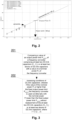
- a first step 101 of a computer-implemented method for fixing an output power limit of a frequency converter voltage differences ⁇ U i between two DC-link circuit capacitors C 1 , C 2 for each of five different values of an output power P out(i) of a frequency converter, where i (1, 2 ..., n), are determined.
- P out(1) 0 kW
- P out(2) 1.6 kW
- P out(3) 3.1 kW
- P out(4) 4 kW
- P out(5) 5.8 kW ( Fig.2 ).
- the DC link circuit capacitors C 1 , C 2 are electrolytic capacitors.
- the application of electrolytic capacitors leads to reduction of production costs of the frequency converter and at the same time provides an appropriate level of reliability of the frequency converter.
- the voltage differences ⁇ U i are determined during stable thermal conditions of the frequency converter. The determination of the voltage differences ⁇ U i can be realized by measuring these values on the DC-link circuit capacitors C 1 , C 2 . Such determination leads to providing five sets of the voltage differences ⁇ U i . Next, in order to eliminate the highest errors occurring during the determination of the voltage differences ⁇ U i a value of 98 th percentile for each set of the voltage differences ⁇ U i is determined 102. The elimination of the highest errors is done through rejection of values of the voltage differences ⁇ U i which are higher than the value of determined percentile.
- ⁇ U f(P out ) from the values of the percentile is determined.
- ⁇ U maxallow 1 3 ⁇ U dc where U dc - a voltage of a DC-link circuit.
- a value of an output power limit P outlimit of the frequency converter for the determined maximum allowable voltage difference ⁇ U maxallow is fixed 105 with a margin of an error factor F me of 0.9.
- the application of the disclosed method allows operation of the frequency converter with ageing DC link circuit capacitors without replacing such capacitors until the scheduled service date.
- the application of the margin of the error factor F me wherein 0 ⁇ F me ⁇ 1, in particular when the margin of the error factor F me is 0.9, improves the safety of frequency converter operation at limited output power.
- the application of the percentile of 98 th further improves accuracy of fixing the output power limit P outlimit .
- 100 samples of the voltage differences ⁇ U i are determined.
- the determination of 100 samples of the voltage differences ⁇ U i improves or even ensures operation of the frequency converter with ageing DC link circuit capacitors without replacing such capacitors until the scheduled service date.
- a value of an output power limit P outlimit of a frequency converter is compared 201 with a value of a nominal power P n of the frequency converter.
- the value of the output power limit P outlimit is fixed by the computer-implemented method for fixing an output power limit of a frequency converter.
- a frequency converter according to the invention is configured to carry out the steps of the computer-implemented method for fixing an output power limit of a frequency converter according to the invention and/or the computer-implemented method for diagnosing conditions of DC-link capacitors according to the invention.
- the frequency converter is shown in Fig.4 in wiring diagram, where C 1 ,C 2 are two DC-link circuit capacitors, R 1 ,R 2 are forming a voltage balancer, U dc is a voltage of a DC-link circuit and U dcx is a voltage of a DC-link circuit midpoint.
- a system 10 for carrying out the steps of the computer-implemented method for fixing an output power limit of a frequency converter according to the invention and/or the computer-implemented method for diagnosing conditions of DC-link capacitors according to the invention comprises a frequency converter 11 and a monitoring apparatus 12 being configured to communicate with the frequency converter 11.
- the monitoring apparatus 12 is further configured to carry out the steps of the computer-implemented method for fixing an output power limit of a frequency converter according to the invention and/or the computer-implemented method for diagnosing conditions of DC-link capacitors according to the invention.
- the system 10 comprises a server 13 instead of the monitoring apparatus 12. The server 13 is configured then to communicate with the frequency converter 11.
- the server 13 is further configured to carry out the steps of the computer-implemented method for fixing an output power limit of a frequency converter according to the invention and/or the computer-implemented method for diagnosing conditions of DC-link capacitors according to the invention.
- the system 10 comprises both the monitoring apparatus 12 and the server 13.
- the monitoring apparatus 12 and the server 13 are configured to communicate with the frequency converter 12 and both the monitoring apparatus 12 and the server 13 are configured to carry out the steps of the computer-implemented method for fixing an output power limit of a frequency converter according to the invention and/or the computer-implemented method for diagnosing conditions of DC-link capacitors according to the invention.
- a computer program comprises means of the program code for performing all steps of the computer-implemented method for fixing an output power limit of a frequency converter according to the invention and/or the computer-implemented method for diagnosing conditions of DC-link capacitors according to the invention, when said program is running on the monitoring apparatus 12.
- the computer program comprises means of the program code for performing all steps of the computer-implemented method for fixing an output power limit of a frequency converter according to the invention and/or the computer-implemented method for diagnosing conditions of DC-link capacitors according to the invention, when said program is running on the server 13.
- the computer program comprises means of the program code for performing all steps of the computer-implemented method for fixing an output power limit of a frequency converter according to the invention and/or the computer-implemented method for diagnosing conditions of DC-link capacitors according to the invention, when said program is running on the monitoring apparatus 12 and the server 13.
- a computer-readable medium stores instructions for performing all the steps of the computer-implemented method for fixing an output power limit of a frequency converter according to the invention and/or the computer-implemented method for diagnosing conditions of DC-link capacitors according to the invention implemented on the monitoring apparatus 12.
- the computer-readable medium stores instructions for performing all the steps of the computer-implemented method for fixing an output power limit of a frequency converter according to the invention and/or the computer-implemented method for diagnosing conditions of DC-link capacitors according to the invention implemented on the server 13.
- the computer-readable medium stores all the steps of the computer-implemented method for fixing an output power limit of a frequency converter according to the invention and/or the computer-implemented method for diagnosing conditions of DC-link capacitors according to the invention implemented on the monitoring apparatus 12 and the server.
Landscapes
- Engineering & Computer Science (AREA)
- Power Engineering (AREA)
- Physics & Mathematics (AREA)
- General Physics & Mathematics (AREA)
- Testing Electric Properties And Detecting Electric Faults (AREA)
Priority Applications (3)
| Application Number | Priority Date | Filing Date | Title |
|---|---|---|---|
| EP22176628.0A EP4287486B1 (de) | 2022-06-01 | 2022-06-01 | Verfahren zur festlegung einer ausgangsleistungsgrenze eines frequenzumrichters und verfahren zur diagnose des zustandes von zwischenkreiskondensatoren |
| CN202310631432.1A CN117155214A (zh) | 2022-06-01 | 2023-05-31 | 用于固定变频器的输出功率限制的方法和诊断dc链路电容器的状况的方法 |
| US18/326,315 US12424944B2 (en) | 2022-06-01 | 2023-05-31 | Method for fixing an output power limit of a frequency converter and a method for diagnosing conditions of DC-link capacitors |
Applications Claiming Priority (1)
| Application Number | Priority Date | Filing Date | Title |
|---|---|---|---|
| EP22176628.0A EP4287486B1 (de) | 2022-06-01 | 2022-06-01 | Verfahren zur festlegung einer ausgangsleistungsgrenze eines frequenzumrichters und verfahren zur diagnose des zustandes von zwischenkreiskondensatoren |
Publications (3)
| Publication Number | Publication Date |
|---|---|
| EP4287486A1 true EP4287486A1 (de) | 2023-12-06 |
| EP4287486C0 EP4287486C0 (de) | 2025-08-06 |
| EP4287486B1 EP4287486B1 (de) | 2025-08-06 |
Family
ID=81877832
Family Applications (1)
| Application Number | Title | Priority Date | Filing Date |
|---|---|---|---|
| EP22176628.0A Active EP4287486B1 (de) | 2022-06-01 | 2022-06-01 | Verfahren zur festlegung einer ausgangsleistungsgrenze eines frequenzumrichters und verfahren zur diagnose des zustandes von zwischenkreiskondensatoren |
Country Status (3)
| Country | Link |
|---|---|
| US (1) | US12424944B2 (de) |
| EP (1) | EP4287486B1 (de) |
| CN (1) | CN117155214A (de) |
Citations (5)
| Publication number | Priority date | Publication date | Assignee | Title |
|---|---|---|---|---|
| US3125720A (en) | 1964-03-17 | Capacitor fault indicator including resistance voltage divider | ||
| US4805063A (en) | 1986-04-22 | 1989-02-14 | Mitsubishi Denki Kabushiki Kaisha | Fault detector for detecting faults in a DC capacitor circuit |
| US6211684B1 (en) | 1998-12-28 | 2001-04-03 | General Atomics | Internal unbalance detection in capacitors |
| US20020085397A1 (en) * | 2000-11-27 | 2002-07-04 | Masaki Suzui | Power converting apparatus, control method therefor, and power generation system |
| US20120153965A1 (en) * | 2010-12-21 | 2012-06-21 | Huang Jui-Kun | Dc capacitor degradation alarm circuit |
Family Cites Families (3)
| Publication number | Priority date | Publication date | Assignee | Title |
|---|---|---|---|---|
| CN104734528B (zh) * | 2013-12-19 | 2018-09-07 | Abb瑞士股份有限公司 | 多相电力驱动器及其功率单元 |
| US9853587B2 (en) * | 2014-04-23 | 2017-12-26 | Yaskawa America, Inc. | System for operating a three-phase variable frequency drive from an unbalanced three-phase or single-phase AC source |
| US11211879B2 (en) * | 2019-09-23 | 2021-12-28 | Rockwell Automation Technologies, Inc. | Capacitor size reduction and lifetime extension for cascaded H-bridge drives |
-
2022
- 2022-06-01 EP EP22176628.0A patent/EP4287486B1/de active Active
-
2023
- 2023-05-31 CN CN202310631432.1A patent/CN117155214A/zh active Pending
- 2023-05-31 US US18/326,315 patent/US12424944B2/en active Active
Patent Citations (5)
| Publication number | Priority date | Publication date | Assignee | Title |
|---|---|---|---|---|
| US3125720A (en) | 1964-03-17 | Capacitor fault indicator including resistance voltage divider | ||
| US4805063A (en) | 1986-04-22 | 1989-02-14 | Mitsubishi Denki Kabushiki Kaisha | Fault detector for detecting faults in a DC capacitor circuit |
| US6211684B1 (en) | 1998-12-28 | 2001-04-03 | General Atomics | Internal unbalance detection in capacitors |
| US20020085397A1 (en) * | 2000-11-27 | 2002-07-04 | Masaki Suzui | Power converting apparatus, control method therefor, and power generation system |
| US20120153965A1 (en) * | 2010-12-21 | 2012-06-21 | Huang Jui-Kun | Dc capacitor degradation alarm circuit |
Also Published As
| Publication number | Publication date |
|---|---|
| CN117155214A (zh) | 2023-12-01 |
| EP4287486C0 (de) | 2025-08-06 |
| EP4287486B1 (de) | 2025-08-06 |
| US12424944B2 (en) | 2025-09-23 |
| US20230396149A1 (en) | 2023-12-07 |
Similar Documents
| Publication | Publication Date | Title |
|---|---|---|
| EP1396065B1 (de) | Notstromversorgungssystem | |
| CN113228451B (zh) | 配电网中的电力质量监测 | |
| EP2156203B1 (de) | Verfahren und einrichtung zur vorhersage eines zustands eines stromversorgungssystems im zeitbereich | |
| EP2290383A1 (de) | Einrichtung zur diagnose der verbleibenden lebensdauer eines kondensators und elektrische stromkompensationseinrichtung mit der einrichtung zur diagnose der verbleibenden lebensdauer | |
| US20120116696A1 (en) | Systems, devices and methods for predicting power electronics failure | |
| US9921270B2 (en) | Battery system with cell voltage detecting units | |
| TW201702872A (zh) | 電子系統及用於估算及預測該電子系統故障之方法 | |
| US20180003745A1 (en) | Method for diagnosing state of capacitor in modular converter | |
| US7912669B2 (en) | Prognosis of faults in electronic circuits | |
| KR20230043370A (ko) | 데이터 센터의 전력 품질을 관리하는 서버, 방법 및 컴퓨터 프로그램 | |
| CN116981950A (zh) | 电池监测单元 | |
| CN117110936A (zh) | 基于时序分析的ups运行状态预测维护系统 | |
| CN112182981A (zh) | 电解电容寿命预测方法、装置、设备及存储介质 | |
| CN118468169A (zh) | 基于物联网的设备故障监测方法、装置、设备及存储介质 | |
| EP4287486A1 (de) | Verfahren zur festlegung einer ausgangsleistungsgrenze eines frequenzumrichters und verfahren zur diagnose des zustandes von zwischenkreiskondensatoren | |
| CN112731008A (zh) | 一种电容老化检测系统及方法 | |
| KR101782223B1 (ko) | 배터리 조절 시스템 진단 장치 및 이를 포함하는 에너지 저장 시스템 | |
| CN114552577B (zh) | 一种输电系统安全性评价方法 | |
| CN111413564A (zh) | 一种超级电容器失效预警方法、系统以及设备 | |
| CN121049660A (zh) | 一种直流供电系统的绝缘在线监测系统及方法 | |
| US11467214B2 (en) | Anomaly detection system and method for electric drives | |
| CN115561565A (zh) | 一种基于网络通信的高压变频器监测装置及方法 | |
| JP2022113975A (ja) | 遮断器異常検出システム | |
| CN119697675B (zh) | 一种5g通信网络路由器故障检测方法、系统及电子设备 | |
| Pascoe et al. | Standby VRLA battery reserve life estimation |
Legal Events
| Date | Code | Title | Description |
|---|---|---|---|
| PUAI | Public reference made under article 153(3) epc to a published international application that has entered the european phase |
Free format text: ORIGINAL CODE: 0009012 |
|
| STAA | Information on the status of an ep patent application or granted ep patent |
Free format text: STATUS: THE APPLICATION HAS BEEN PUBLISHED |
|
| AK | Designated contracting states |
Kind code of ref document: A1 Designated state(s): AL AT BE BG CH CY CZ DE DK EE ES FI FR GB GR HR HU IE IS IT LI LT LU LV MC MK MT NL NO PL PT RO RS SE SI SK SM TR |
|
| STAA | Information on the status of an ep patent application or granted ep patent |
Free format text: STATUS: REQUEST FOR EXAMINATION WAS MADE |
|
| 17P | Request for examination filed |
Effective date: 20240528 |
|
| RBV | Designated contracting states (corrected) |
Designated state(s): AL AT BE BG CH CY CZ DE DK EE ES FI FR GB GR HR HU IE IS IT LI LT LU LV MC MK MT NL NO PL PT RO RS SE SI SK SM TR |
|
| GRAP | Despatch of communication of intention to grant a patent |
Free format text: ORIGINAL CODE: EPIDOSNIGR1 |
|
| STAA | Information on the status of an ep patent application or granted ep patent |
Free format text: STATUS: GRANT OF PATENT IS INTENDED |
|
| RIC1 | Information provided on ipc code assigned before grant |
Ipc: H02M 1/15 20060101ALI20250501BHEP Ipc: H02M 1/32 20070101ALI20250501BHEP Ipc: H02M 7/5387 20070101ALI20250501BHEP Ipc: H02M 5/458 20060101AFI20250501BHEP |
|
| GRAS | Grant fee paid |
Free format text: ORIGINAL CODE: EPIDOSNIGR3 |
|
| INTG | Intention to grant announced |
Effective date: 20250521 |
|
| GRAA | (expected) grant |
Free format text: ORIGINAL CODE: 0009210 |
|
| STAA | Information on the status of an ep patent application or granted ep patent |
Free format text: STATUS: THE PATENT HAS BEEN GRANTED |
|
| AK | Designated contracting states |
Kind code of ref document: B1 Designated state(s): AL AT BE BG CH CY CZ DE DK EE ES FI FR GB GR HR HU IE IS IT LI LT LU LV MC MK MT NL NO PL PT RO RS SE SI SK SM TR |
|
| REG | Reference to a national code |
Ref country code: GB Ref legal event code: FG4D |
|
| REG | Reference to a national code |
Ref country code: CH Ref legal event code: EP |
|
| REG | Reference to a national code |
Ref country code: DE Ref legal event code: R096 Ref document number: 602022018750 Country of ref document: DE |
|
| REG | Reference to a national code |
Ref country code: IE Ref legal event code: FG4D |
|
| U01 | Request for unitary effect filed |
Effective date: 20250807 |
|
| U07 | Unitary effect registered |
Designated state(s): AT BE BG DE DK EE FI FR IT LT LU LV MT NL PT RO SE SI Effective date: 20250820 |
|
| PG25 | Lapsed in a contracting state [announced via postgrant information from national office to epo] |
Ref country code: IS Free format text: LAPSE BECAUSE OF FAILURE TO SUBMIT A TRANSLATION OF THE DESCRIPTION OR TO PAY THE FEE WITHIN THE PRESCRIBED TIME-LIMIT Effective date: 20251206 |
|
| PG25 | Lapsed in a contracting state [announced via postgrant information from national office to epo] |
Ref country code: NO Free format text: LAPSE BECAUSE OF FAILURE TO SUBMIT A TRANSLATION OF THE DESCRIPTION OR TO PAY THE FEE WITHIN THE PRESCRIBED TIME-LIMIT Effective date: 20251106 |
|
| PG25 | Lapsed in a contracting state [announced via postgrant information from national office to epo] |
Ref country code: HR Free format text: LAPSE BECAUSE OF FAILURE TO SUBMIT A TRANSLATION OF THE DESCRIPTION OR TO PAY THE FEE WITHIN THE PRESCRIBED TIME-LIMIT Effective date: 20250806 |
|
| PG25 | Lapsed in a contracting state [announced via postgrant information from national office to epo] |
Ref country code: GR Free format text: LAPSE BECAUSE OF FAILURE TO SUBMIT A TRANSLATION OF THE DESCRIPTION OR TO PAY THE FEE WITHIN THE PRESCRIBED TIME-LIMIT Effective date: 20251107 |
|
| PG25 | Lapsed in a contracting state [announced via postgrant information from national office to epo] |
Ref country code: PL Free format text: LAPSE BECAUSE OF FAILURE TO SUBMIT A TRANSLATION OF THE DESCRIPTION OR TO PAY THE FEE WITHIN THE PRESCRIBED TIME-LIMIT Effective date: 20250806 |
|
| PG25 | Lapsed in a contracting state [announced via postgrant information from national office to epo] |
Ref country code: RS Free format text: LAPSE BECAUSE OF FAILURE TO SUBMIT A TRANSLATION OF THE DESCRIPTION OR TO PAY THE FEE WITHIN THE PRESCRIBED TIME-LIMIT Effective date: 20251106 |
|
| PG25 | Lapsed in a contracting state [announced via postgrant information from national office to epo] |
Ref country code: ES Free format text: LAPSE BECAUSE OF FAILURE TO SUBMIT A TRANSLATION OF THE DESCRIPTION OR TO PAY THE FEE WITHIN THE PRESCRIBED TIME-LIMIT Effective date: 20250806 |
|
| PG25 | Lapsed in a contracting state [announced via postgrant information from national office to epo] |
Ref country code: SM Free format text: LAPSE BECAUSE OF FAILURE TO SUBMIT A TRANSLATION OF THE DESCRIPTION OR TO PAY THE FEE WITHIN THE PRESCRIBED TIME-LIMIT Effective date: 20250806 |
|
| PG25 | Lapsed in a contracting state [announced via postgrant information from national office to epo] |
Ref country code: CZ Free format text: LAPSE BECAUSE OF FAILURE TO SUBMIT A TRANSLATION OF THE DESCRIPTION OR TO PAY THE FEE WITHIN THE PRESCRIBED TIME-LIMIT Effective date: 20250806 |
|
| PG25 | Lapsed in a contracting state [announced via postgrant information from national office to epo] |
Ref country code: SK Free format text: LAPSE BECAUSE OF FAILURE TO SUBMIT A TRANSLATION OF THE DESCRIPTION OR TO PAY THE FEE WITHIN THE PRESCRIBED TIME-LIMIT Effective date: 20250806 |