EP4290200B1 - Mechanische antriebsvorrichtung mit einem schallrad-drehmomentmesser, kraftübertragungsgehäuse mit einer solchen mechanischen antriebsvorrichtung und flugzeug - Google Patents
Mechanische antriebsvorrichtung mit einem schallrad-drehmomentmesser, kraftübertragungsgehäuse mit einer solchen mechanischen antriebsvorrichtung und flugzeug Download PDFInfo
- Publication number
- EP4290200B1 EP4290200B1 EP23167468.0A EP23167468A EP4290200B1 EP 4290200 B1 EP4290200 B1 EP 4290200B1 EP 23167468 A EP23167468 A EP 23167468A EP 4290200 B1 EP4290200 B1 EP 4290200B1
- Authority
- EP
- European Patent Office
- Prior art keywords
- teeth
- mechanical
- intermediate shaft
- tooth
- mechanical device
- Prior art date
- Legal status (The legal status is an assumption and is not a legal conclusion. Google has not performed a legal analysis and makes no representation as to the accuracy of the status listed.)
- Active
Links
Images


Classifications
-
- B—PERFORMING OPERATIONS; TRANSPORTING
- B64—AIRCRAFT; AVIATION; COSMONAUTICS
- B64D—EQUIPMENT FOR FITTING IN OR TO AIRCRAFT; FLIGHT SUITS; PARACHUTES; ARRANGEMENT OR MOUNTING OF POWER PLANTS OR PROPULSION TRANSMISSIONS IN AIRCRAFT
- B64D35/00—Transmitting power from power plants to propellers or rotors; Arrangements of transmissions
-
- F—MECHANICAL ENGINEERING; LIGHTING; HEATING; WEAPONS; BLASTING
- F16—ENGINEERING ELEMENTS AND UNITS; GENERAL MEASURES FOR PRODUCING AND MAINTAINING EFFECTIVE FUNCTIONING OF MACHINES OR INSTALLATIONS; THERMAL INSULATION IN GENERAL
- F16H—GEARING
- F16H1/00—Toothed gearings for conveying rotary motion
- F16H1/02—Toothed gearings for conveying rotary motion without gears having orbital motion
- F16H1/20—Toothed gearings for conveying rotary motion without gears having orbital motion involving more than two intermeshing members
-
- B—PERFORMING OPERATIONS; TRANSPORTING
- B64—AIRCRAFT; AVIATION; COSMONAUTICS
- B64C—AEROPLANES; HELICOPTERS
- B64C27/00—Rotorcraft; Rotors peculiar thereto
- B64C27/04—Helicopters
- B64C27/12—Rotor drives
- B64C27/14—Direct drive between power plant and rotor hub
-
- F—MECHANICAL ENGINEERING; LIGHTING; HEATING; WEAPONS; BLASTING
- F16—ENGINEERING ELEMENTS AND UNITS; GENERAL MEASURES FOR PRODUCING AND MAINTAINING EFFECTIVE FUNCTIONING OF MACHINES OR INSTALLATIONS; THERMAL INSULATION IN GENERAL
- F16D—COUPLINGS FOR TRANSMITTING ROTATION; CLUTCHES; BRAKES
- F16D11/00—Clutches in which the members have interengaging parts
- F16D11/14—Clutches in which the members have interengaging parts with clutching members movable only axially
-
- F—MECHANICAL ENGINEERING; LIGHTING; HEATING; WEAPONS; BLASTING
- F16—ENGINEERING ELEMENTS AND UNITS; GENERAL MEASURES FOR PRODUCING AND MAINTAINING EFFECTIVE FUNCTIONING OF MACHINES OR INSTALLATIONS; THERMAL INSULATION IN GENERAL
- F16H—GEARING
- F16H57/00—General details of gearing
- F16H57/04—Features relating to lubrication or cooling or heating
- F16H57/045—Lubricant storage reservoirs, e.g. reservoirs in addition to a gear sump for collecting lubricant in the upper part of a gear case
-
- G—PHYSICS
- G01—MEASURING; TESTING
- G01L—MEASURING FORCE, STRESS, TORQUE, WORK, MECHANICAL POWER, MECHANICAL EFFICIENCY, OR FLUID PRESSURE
- G01L3/00—Measuring torque, work, mechanical power, or mechanical efficiency, in general
- G01L3/02—Rotary-transmission dynamometers
- G01L3/04—Rotary-transmission dynamometers wherein the torque-transmitting element comprises a torsionally-flexible shaft
- G01L3/10—Rotary-transmission dynamometers wherein the torque-transmitting element comprises a torsionally-flexible shaft involving electric or magnetic means for indicating
- G01L3/109—Rotary-transmission dynamometers wherein the torque-transmitting element comprises a torsionally-flexible shaft involving electric or magnetic means for indicating involving measuring phase difference of two signals or pulse trains
Definitions
- the present invention lies in the field of power transmission devices.
- the present invention relates to a mechanical drive device provided with a phonic wheel torque meter, as well as a power transmission box for an aircraft provided with such a mechanical drive device and an aircraft comprising such a power transmission box.
- a mechanical rotational drive device allows mechanical torque and, consequently, power to be transmitted between two rotating elements, for example between an input pinion and an output pinion.
- Such a mechanical drive device may be arranged between a drive system, such as a motor, connected to the input pinion using for example a first toothed wheel and a receiving system, such as a rotor, connected to the output pinion using for example a second toothed wheel.
- a drive system such as a motor
- a receiving system such as a rotor
- Such a mechanical drive device may also be arranged in a mechanical system positioned between a drive system and a receiving system.
- a mechanical system is for example a mechanical power transmission box of an aircraft positioned between on the one hand one or more engines and on the other hand one or more rotors.
- This mechanical system may comprise one or more reduction stages provided for example with gears, pinions and/or toothed wheels. Such a mechanical drive device may then be arranged between two reduction stages of the mechanical system.
- a mechanical drive device may include a torque meter, providing information relating to the mechanical torque transmitted between the input pinion and the output pinion.
- a torque meter may be, for example, a tone wheel torque meter.
- a phonic wheel torque meter makes it possible to obtain a measurement of the transmitted torque by comparing the position of a drive shaft subjected to this torque and therefore likely to deform with the position of a reference shaft rotating coaxially and synchronised with the drive shaft without being subjected to this torque.
- one end of the reference shaft is fixed integrally to the drive shaft, preferably close to the mechanical connection linking the drive shaft to the input or output pinion.
- the other end of the reference shaft comprises indexes, for example teeth or orifices.
- the drive shaft also comprises indexes at one of its ends opposite the connection with the reference shaft, and preferably close to the mechanical connection linking the drive shaft to the output or input pinion.
- the indexes of the drive shaft and the reference shaft are generally located at the same level in order to be detected by the same sensor during the rotation of the drive and reference shafts.
- a twist of the drive shaft under the effect of the transmitted mechanical torque will then be caused between the respective connections with the input and output gears. This twist can then be characterized by the angular offset of the indexes of this drive shaft relative to the indexes of the reference shaft not undergoing such a twist.
- a sensor can then detect the passage of these indexes, and transmit information relating to these passages to a computer so that the computer deduces the torque transmitted according to a predetermined law.
- the angular offset between the indexes must be significant, for example at least a few degrees. Consequently, the useful length of the drive shaft subjected to torsional deformation must be significant. This useful length of the drive shaft is defined in particular according to the torque values that the torque meter will have to measure. However, the arrangement of a very long drive shaft can be tricky.
- the mechanical connection between the drive shaft and the input or output pinion which is located opposite the indexes is therefore positioned near or at the end of the drive shaft.
- the dimensions of this mechanical connection therefore contribute, with the dimensions of the drive shaft, to defining the dimensions of the mechanical drive device, and in particular the size of this mechanical drive device along its axis of rotation.
- a mechanical power transmission box may be an important and imposed parameter, particularly when the mechanical power transmission box is fitted to a vehicle and in particular an aircraft. Consequently, the use of a mechanical drive device equipped with a phonic wheel torque meter in such a mechanical power transmission box may prove complex.
- the dimensions of the mechanical connection between the drive shaft and the input or output pinion output may require that this mechanical connection be located near, or even below, the level of a lubricating liquid of the mechanical power transmission box, thus causing a bubbling phenomenon which may be detrimental to the operation of this mechanical connection, for example by causing expansion of the parts of the mechanical connection with the lubricating liquid hotter than the temperature inside the mechanical power transmission box.
- the technological background of the invention includes in particular the documents US 2016/0195442 , US 2020/0003290 , US 9841333 , FR 2373044 , WO 2009/141261 , FR 3032525 And US 2015/0211380 .
- the present invention therefore aims to propose an alternative solution for the mechanical drive of the elements of such a mechanical drive device aimed at limiting the axial size of the mechanical drive device.
- the present invention relates, for example, to a mechanical device comprising an input pinion and an output pinion which are movable in rotation about an axis of rotation AX, an intermediate shaft extending longitudinally along the axis of rotation AX from a first proximal end to a first distal end, a first mechanical connection connecting the intermediate shaft and the input pinion, a second mechanical connection connecting the first distal end of the intermediate shaft and the output pinion, the mechanical device comprising a torque meter cooperating with the intermediate shaft.
- the mechanical device according to the invention is remarkable in that the torque meter is a tone wheel torque meter provided with a reference shaft extending longitudinally along the axis of rotation AX from a second proximal end to a second distal end, the reference shaft being arranged at least partially inside the intermediate shaft and being coaxial with the intermediate shaft, the second distal end of the reference shaft being connected to the intermediate shaft, the torque meter comprising at least one measuring index secured to the intermediate shaft and arranged at the first proximal end as well as at least one reference index secured to the reference shaft and arranged at the second proximal end.
- the mechanical device according to the invention is also remarkable in that the intermediate shaft is coaxial with the input pinion and with the output pinion around the axis of rotation AX and that the second mechanical rotation drive connection comprises a series of first teeth arranged on the first distal end of the intermediate shaft and a series of second teeth arranged on the output pinion, around the first teeth facing the axis of rotation AX, a drive ring comprising a series of connecting teeth separated by radial intertooth spaces, each first tooth and each second tooth being in contact with the connecting teeth in a radial intertooth space, and a fixing device axially connecting along the axis of rotation AX the drive ring with the intermediate shaft and the output pinion.
- the input pinion and the output pinion are mechanically connected in rotation about the axis of rotation AX by means of the first mechanical connection, the intermediate shaft and the second mechanical connection.
- the first mechanical rotational drive connection may be a permanent or non-permanent mechanical connection, for example disengageable.
- the input pinion and the intermediate shaft are thus driven about the axis of rotation AX via the first mechanical connection synchronously and coaxially.
- the second mechanical drive connection is a permanent mechanical connection.
- the output pinion and the intermediate shaft are thus driven around the axis of rotation AX via the second mechanical connection synchronously and coaxially.
- the installation of the torque meter in the mechanical device according to the invention makes it possible to permanently know the mechanical torque transmitted between the input pinion and the output pinion.
- the drive ring of the second mechanical connection is annular around the axis of rotation AX and therefore has an orifice in its center.
- the drive ring allows a mechanical torque to be transmitted between the intermediate shaft and the output pinion, via the first teeth, the second teeth and the connecting teeth.
- Each first tooth extends from a tooth root to a tooth tip parallel to the axis of rotation AX.
- each connecting tooth extends from a tooth root to a tooth tip parallel to the axis of rotation AX.
- the tooth root connects this tooth to the body of the part comprising this tooth, namely the body of the intermediate shaft for a first tooth and the body of the drive ring for a connecting tooth.
- a tooth tip is the free end of a tooth.
- the first teeth arranged on the first distal end of the intermediate shaft cooperate and are in contact with the connecting teeth of the drive ring.
- Each first tooth is located in a radial intertooth space between two connecting teeth while being in contact with these two connecting teeth.
- the first teeth and the connecting teeth thus fit together axially, parallel to the axis of rotation AX and not radially as in the case of a meshing between a pinion and a toothed wheel or with splines for example.
- the mechanical torque is thus transmitted between the intermediate shaft and the drive ring.
- the second teeth arranged on the output pinion cooperate and are in contact with the connecting teeth of the drive ring.
- the second teeth are located outside the first teeth with respect to the axis of rotation AX. Similar to the first teeth, each second tooth extends from a tooth root to a tooth tip parallel to the axis of rotation AX. Each second tooth is located in a radial intertooth space between two connecting teeth while being in contact with these two connecting teeth.
- the second teeth and the connecting teeth thus also fit together axially, parallel to the axis of rotation AX. The mechanical torque is thus transmitted between the drive ring and the output pinion.
- a fixing device provides an axial connection along the axis of rotation AX between the drive ring, the intermediate shaft and the output pinion, thus holding the first and second teeth in radial intertooth spaces between two connecting teeth.
- a rotation of the input pinion can thus cause a rotation of the output pinion synchronously and coaxially with the input pinion depending on the type of the first mechanical connection used.
- the input pinion is then connected via a gear wheel or a reduction gear to a drive system, such as a motor for example.
- the output pinion is connected, via a toothed wheel or a reduction device, to a receiving system, such as a rotor for example.
- the mechanical device according to the invention makes it possible in particular to transmit a rotational movement and a mechanical torque between the input pinion and the output pinion with minimum axial bulk, in particular thanks to the second mechanical connection, while allowing the transmission of a significant mechanical torque.
- the mechanical device according to the invention may comprise one or more of the following characteristics, taken alone or in combination.
- the first mechanical rotational drive connection may be a permanent connection.
- the first mechanical connection may include one or more keys, one or more pins, or splines.
- the first mechanical rotational drive link may be a disengageable link.
- the first mechanical connection may comprise a freewheel allowing only the output pinion to be driven by the input pinion, the input pinion then being connected to a drive system, and the output pinion being connected to a receiving system.
- the first mechanical connection may alternatively comprise a freewheel allowing only the input pinion to be driven by the output pinion in a single direction of rotation about the axis of rotation AX.
- the output pinion is then connected to a drive system, and the input pinion is connected to a receiving system.
- the first teeth and the second teeth can be convex in shape and the connecting teeth can be concave in shape in a plane perpendicular to the axis of rotation AX.
- the first teeth and the second teeth are of identical shapes, the shape of the connecting teeth being complementary to the shapes of the first and second teeth.
- the contacts on the one hand between the first teeth and the connecting teeth and on the other hand between the second teeth and the connecting teeth are made on a surface thus allowing the transmission of a significant mechanical torque, while limiting the wear or the matting of the first teeth, the second teeth and the connecting teeth.
- These shapes of the first teeth, the second teeth and the connecting teeth also make it possible to advantageously ensure coaxiality between the intermediate shaft and the output pinion.
- first teeth and the second teeth may be concave in shape and the connecting teeth may be convex in shape in a plane perpendicular to the axis of rotation AX.
- the first teeth and the second teeth are of identical shapes, the shape of the connecting teeth being complementary to the shapes of the first and second teeth.
- first teeth, second teeth and connecting teeth are of the Curvic ® type.
- each intertooth space can accommodate a first tooth and a second tooth, each intertooth space being longitudinally opposite a first tooth and a second tooth.
- the mechanical torque transmitted between the intermediate shaft and the output pinion can then be maximized.
- the first teeth, the second teeth and the connecting teeth can each extend in azimuth relative to the axis of rotation AX between two inclined faces.
- Each of the faces is thus inclined relative to a direction parallel to the axis of rotation AX at an angle of between 5 and 15 degrees (5° and 15°).
- an intersection of these flanks with a plane parallel to the axis of rotation and tangent to a circle centered on the axis of rotation AX forms an angle of between 5° and 15° with a straight line of this plane parallel to the axis of rotation AX.
- This angle of between 5° and 15° is, for example, smaller than the angle traditionally used for Curvic ® type transmission systems, which is around 30°. This small angle makes it possible to increase the number of teeth carried by the drive ring, the intermediate shaft and the output pinion at the second mechanical connection.
- each connecting tooth can comprise radially two teeth separated by a separation space, the two teeth comprising an internal connecting tooth and an external connecting tooth, the external connecting teeth being located around the internal connecting teeth with respect to the axis of rotation AX.
- the internal connecting teeth thus cooperate with the first teeth and the external connecting teeth cooperate with the second teeth.
- the internal connecting teeth thus cooperate only with the first teeth while the external connecting teeth cooperate only with the second teeth, the internal connecting teeth being located between the external connecting teeth and the axis of rotation AX.
- the separation space has a circular arc groove centered on the axis of rotation AX.
- the fixing device can comprise a screw and a nut, the screw comprising a threaded external cylindrical surface cooperating with a tapped internal cylindrical surface of the intermediate shaft, the drive ring being arranged between the screw and the intermediate shaft, the nut comprising a tapped internal cylindrical surface cooperating with a threaded external surface of the output pinion, the drive ring being arranged between the nut and the output pinion.
- This fixing device thus makes it possible to maintain axially along the axis of rotation AX the drive ring, the intermediate shaft and the output pinion despite the axial forces which may appear at the level of the first teeth, the second teeth and the connecting teeth.
- the torque meter can comprise a sensor and a calculator, the sensor being configured to measure relative angular positions of said at least one measurement index and said at least one reference index relative to the axis of rotation AX, the calculator being configured to determine a mechanical torque transmitted between the input pinion and the output pinion according to the relative angular positions.
- a calibration of the torque meter can be carried out to determine the thermal expansions of the components of the mechanical device according to the invention occurring during operation of the mechanical device and take into account these thermal expansions to determine their effects on the relative angular positions of said at least one measurement index and said at least one reference index, and consequently on the values of the measured torques.
- the calculator can for example be configured to apply a predetermined law, established for example by tests or simulation, linking said relative angular positions and the mechanical torque. transmitted between the input pinion and the output pinion.
- This predetermined law takes into account in particular the thermal expansions of the components of the mechanical device.
- said at least one measuring index and said at least one reference index can be arranged in a first plane P perpendicular to the axis of rotation AX.
- the same sensor can detect the passage of said at least one measuring index and said at least one reference index and deduce therefrom relative angular positions of said at least one measuring index and said at least one reference index, and consequently an angular offset between a measuring index and a reference index.
- the intermediate shaft can be arranged at least partially inside the input pinion and the output pinion.
- the reference shaft can be linked to the intermediate shaft by a zero-degree-of-freedom embedding type connection, comprising for example at least one key, at least one pin or splines or even a hoop...
- the present invention also relates to a power transmission box comprising a mechanical device as previously described.
- the power transmission box comprises a housing in which the mechanical device is arranged and at the bottom of which a lubricating liquid is located.
- the second mechanical connection is positioned above the lubricating liquid when the power transmission box is at a reference position.
- the small axial size of the second mechanical connection avoids, despite a significant minimum length of the intermediate shaft necessary to allow precise measurement of the transmitted torque, that this second mechanical connection is located below the level of lubricating liquid, and therefore at least partially in the lubricating liquid, further avoiding the phenomenon of bubbling of the second mechanical connection in the lubricating liquid.
- the reference position is, for example, a horizontal position of the power transmission box in a terrestrial reference frame, for example when a vehicle comprising this power transmission box is stopped on horizontal ground.
- the present invention finally aims at an aircraft comprising a power transmission box as previously described, the power transmission box being arranged between at least one engine and at least one rotor of the aircraft.
- Such an aircraft is, for example, a rotary wing aircraft comprising one or more engines and one or more rotors, such as a lift rotor and an auxiliary anti-torque rotor, as well as a power transmission box enabling the engine(s) to drive the rotor(s) in rotation.
- a rotary wing aircraft comprising one or more engines and one or more rotors, such as a lift rotor and an auxiliary anti-torque rotor, as well as a power transmission box enabling the engine(s) to drive the rotor(s) in rotation.
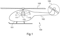
- FIG. 1 represents a rotary wing aircraft 100 of the rotorcraft type.
- This aircraft 100 may comprise an airframe 101, a main rotor 105 participating at least partially in the lift of the aircraft 100 and possibly an auxiliary rotor 106 arranged at the end of a tail boom 102 as well as a power transmission box 10.
- the power transmission box 10 is driven in rotation by a power plant 110 provided with at least one engine 111, 112 and drives the main rotor 105 and possibly the auxiliary rotor 106 in rotation, thus making it possible to transmit mechanical power from the engine(s) 111, 112 to the main rotor 105 and possibly to the auxiliary rotor 106.
- the power transmission box 10 comprises on the one hand, at least one input shaft 11 connected to the power plant 110 and on the other hand, a mast 12 connected to the rotor. main 105.
- An output shaft (not shown) of the power transmission box 10 may also be connected to the auxiliary rotor 106.
- the power transmission box 10 may comprise one or more reduction stages provided for example with gears, pinions and/or toothed wheels.
- the power transmission box 10 may also comprise a mechanical device 1 arranged for example between two reduction stages. A sectional view of this mechanical device 1 is shown in the figure 2 .
- the mechanical device 1 can alternatively be arranged in any mechanical system, provided with pinions and/or toothed wheels and equipping for example a vehicle or a machine.
- the mechanical device 1 comprises an input pinion 2 and an output pinion 3 movable in rotation about an axis of rotation AX.
- the axis of rotation AX is located in the section plane of the view shown in the figure 2 .
- the input pinion 2 has teeth 21 which can, for example, be connected via a gear wheel or a reduction gear to a drive system.
- the output pinion 3 has teeth 31 which can be connected via a gear wheel or a reduction gear to a receiving system.
- the input pinion 2 can be connected via two toothed wheels to the two input shafts 11 and, consequently, to the two motors 111, 112 of the power plant 110 while the output pinion 3 can be connected via a reduction gear to the mast 12 and, consequently, to the rotor 105, 106.
- input gear 2 and output gear 3 can be reversed, output gear 3 can then be connected to at least an input shaft 11 then to a drive system while the input pinion 2 can be connected to a mast 12 then to a receiving system.
- the mechanical device 1 also comprises an intermediate shaft 4 extending longitudinally along the axis of rotation AX, from a first proximal end 41 to a first distal end 42.
- the intermediate shaft 4 extends at least partially inside the input pinion 2 and the output pinion 3, being coaxial with the input pinion 2 and with the output pinion 3, around the axis of rotation AX.
- the mechanical device 1 comprises rotation guide devices 15, such as ball or roller bearings for example.
- Such rotation guide devices 15 are for example arranged between the input pinion 2 and the intermediate shaft 4, between the input pinion 2 and the output pinion 3, between a frame (not shown for the sake of clarity of the figure 2 ) of the mechanical device 1 and the input pinion 2, and between this frame and the output pinion 3.
- the tracks of these rotation guide devices 15 can be integrated into these components 2, 3, 4 of the mechanical device 1 or else be added, these rotation guide devices 15 then comprising for example an inner ring and/or an outer ring.
- the mechanical device 1 also comprises a first mechanical connection 5, a second mechanical connection 6 and a torque meter 7.
- the first mechanical connection 5 secures at least in rotation about the axis of rotation AX the input pinion 2 with the intermediate shaft 4, preferably near the first proximal end 41.
- the first mechanical connection 5 for driving in rotation may be a permanent connection so that the pinion input gear 2 and output gear 3 are permanently connected at least in rotation to each other.
- the first mechanical connection 5 may in this case comprise splines or one or more keys or one or more pins for example.
- the first mechanical connection 5 may also be a zero-degree-of-freedom embedding type connection.
- the first mechanical rotation drive connection 5 may be a disengageable connection.
- the first mechanical connection 5 may comprise a freewheel 55, an internal part of the freewheel 55 being connected to the intermediate shaft 4 and an external part of the freewheel 55 being connected to the input pinion 2.
- the freewheel 55 thus allows, for example, only a drive of the output pinion 4 by the input pinion 2 in a direction of rotation about the axis of rotation AX.
- the second mechanical connection 6 makes it possible to connect the intermediate shaft 4 and the output pinion 3 in rotation about the axis of rotation AX using a drive ring 60.
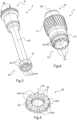
- Individual perspective views of the intermediate shaft 4, the output pinion 3 and the drive ring 60 are shown respectively in the Figures 3, 4 and 5 .
- the intermediate shaft 4 comprises first teeth 45 arranged at the first distal end 42 and a bore opening onto the first distal end 42.
- This bore comprises a tapped inner cylindrical surface 47.
- the first teeth 45 extend from a tooth root towards a tooth tip parallel to the axis of rotation AX.
- the output pinion 3 comprises a proximal end 33 and a distal end 32 as well as second teeth 35 arranged at the distal end 32 and an outer surface 37 threaded and located near the second teeth 35, or even adjacent to the second teeth 35.
- the second teeth 35 extend from a tooth root to a tooth tip parallel to the axis of rotation AX.
- the drive ring 60 comprises connecting teeth 65 separated by radial intertooth spaces 653 and a cylindrical orifice 62.
- the connecting teeth 65 extend from a tooth root towards a tooth tip parallel to the axis of rotation AX.
- the first teeth 45 thus cooperate with the connecting teeth 65 in order to connect in rotation the intermediate shaft 4 and the drive ring 60.
- Each first tooth 45 occupies a radial intertooth space 653, being in contact with the connecting teeth 65 in this intertooth space 653.
- the first teeth 45 and the connecting teeth 65 thus mesh with each other axially, parallel to the axis of rotation AX.
- the second teeth 35 cooperate with the connecting teeth 65, the second teeth 35 being positioned around the first teeth 45 with respect to the axis of rotation AX, in order to connect in rotation the output pinion 3 and the drive ring 60.
- Each second tooth 35 occupies a radial intertooth space 653, being in contact with the connecting teeth 65 in this intertooth space 653.
- the second teeth 35 and the connecting teeth 65 thus mesh with each other axially, parallel to the axis of rotation AX.
- the second mechanical connection 6 thus comprises the first teeth 45, the second teeth 35 and the connecting teeth 65 as well as the drive ring 60 itself.
- each intertooth space 653 is located opposite a first tooth 45 and a second tooth 35 longitudinally along the axis of rotation AX.
- Each space interdent 653 thus accommodates a first tooth 45 and a second tooth 35.
- the second mechanical connection 6 also comprises a fixing device 66 holding axially along the axis of rotation AX the drive ring 60 with the intermediate shaft 4 and the output pinion 3, and consequently the first teeth 45 and the second teeth 35 in the intertooth spaces 653, and therefore in contact with the connecting teeth 65.
- the fixing device 66 comprises a screw 67 and a nut 68 shown in the figure 2 .
- the screw 67 has a threaded outer cylindrical surface 671 and a head 672.
- the threaded outer cylindrical surface 671 is configured to be assembled with the tapped inner cylindrical surface 47 of the intermediate shaft 4, this outer cylindrical surface 671 passing through the cylindrical orifice 62 of the drive ring 60.
- the head 672 then bears against the drive ring 60, thus holding the drive ring 60 against the intermediate shaft 4.
- the drive ring 60 is thus positioned between the screw 67 and the intermediate shaft 4.
- the nut 68 has a threaded inner cylindrical surface 681 and a collar 682.
- the threaded inner cylindrical surface 681 is configured to be assembled with the threaded outer cylindrical surface 37 of the output pinion 3, this inner cylindrical surface 681 being positioned outside the drive ring 60 with respect to the axis of rotation AX.
- the collar 682 then bears against the drive ring 60, thus holding the drive ring 60 against the output pinion 3.
- the drive ring 60 is thus positioned between the nut 68 and the output pinion 3.
- the torque meter 7 is a phonic wheel torque meter and makes it possible to measure a torque transmitted between the input pinion 2 and the output pinion 3.
- This torque meter 7 comprises at least one measuring index 48 secured to the intermediate shaft 4 and arranged at the first proximal end 41 and a reference shaft 8 extending longitudinally along the axis of rotation AX from a second proximal end 81 to a second distal end 82.
- the reference shaft 8 is provided with at least one reference index 88 positioned at the second proximal end 81.
- the measuring index(es) 48 and the reference index(es) 88 are preferably arranged such that a first plane P1 perpendicular to the axis of rotation AX intersects the measuring index(es) 48 and the reference index(es) 88.
- Such a measuring index 48 may comprise, for example, a protrusion, such as a tooth protruding from a ring forming the first proximal end 41 of the intermediate shaft 4 or a shape projecting from the flank of this ring.
- a measuring index 48 may alternatively comprise a groove hollowed out in the flank of the first proximal end 41 or other hollow shapes.
- the reference index 88 may be similar to or even identical to the measurement index 48. For example, if the measurement index 48 has a protrusion, the reference index 88 also has a protrusion. Alternatively, if the measurement index 48 has a recessed groove, the reference index 88 also has a recessed groove. In addition, the numbers of reference indices 88 and measurement indices 48 are equal. For example, the intermediate shaft 4 may have four measurement indices 48 and the reference shaft 8 may have four reference indices 88 equally distributed around the axis of rotation AX.
- the reference shaft 8 is coaxial with the intermediate shaft 4 and arranged at least partially inside the intermediate shaft 4. for example, only the reference index(es) 88 can be arranged outside the intermediate shaft 4, beyond the first proximal end 41.
- the reference shaft 8 is secured to the intermediate shaft 4 at the second distal end 82, and close to the first distal end 42, for example by a zero-degree-of-freedom embedding type connection.
- the intermediate shaft 4 deforms in torsion between the first mechanical connection 5 and the second mechanical connection 6, and therefore substantially between the first proximal end 41 and the first distal end 42 under the effect of the torque transmitted between the input pinion 2 and the output pinion 3.
- the reference shaft 8 is fixed to the intermediate shaft 4 only at the second distal end 82 and is therefore not subjected to any deformation, except that induced by the rotation speed of the reference shaft 8 which is very low and can therefore be neglected.
- the torque meter 7 may comprise at least one sensor 75 and a calculator 73.
- the sensor 75 may be configured to measure the relative angular positions of said at least one measuring index 48 and said at least one reference index 88 relative to the axis of rotation AX, for example in the plane P1.
- the sensor 75 may be configured to measure the absolute angular positions in a reference frame linked to the mechanical device 1 of the measuring index(es) 48 and of the reference index(es) 88 relative to the axis of rotation AX, for example in the plane P1.
- a single sensor 75 may be sufficient. The use of several sensors 75 may allow redundancy of measurements and/or the use of an average value of these measurements for example.
- the sensor then transmits to the computer 73 at least one signal, digital or analog, electrical or optical, carrying information relating to these angular positions, for example by a wired or wireless connection.
- the computer 73 processes this information and determines the mechanical torque transmitted between the input pinion 2 and the output pinion 3 by applying for example a predetermined law according to the measured angular positions.
- the angular offset between a measuring index 48 and a reference index 88 must be significant, for example of the order of several degrees.
- the length of the intermediate shaft 4 must be sufficient, this length being determined according to the torque to be transmitted and therefore to be measured, and the targeted angular offset. This length of the intermediate shaft 4 can then become a dimensioning characteristic of the mechanical device 1, or even of the main transmission box 100.
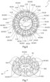
- FIG. 6 represents a sectional view, perpendicular to the axis of rotation AX of the second mechanical connection 6 of the mechanical device 1 of the figure 2 .
- Each intertooth space 653 accommodates a first tooth 45 and a second tooth 35.
- the first teeth 45 and the second teeth 35 are of concave shape while the connecting teeth 65 are of convex shape.
- the radii R, R' of these concave and convex shapes are equal.
- the shapes of these first and second teeth 45, 35 are identical and are complementary to the shape of the teeth connecting link 65, thus allowing optimal operation of the second mechanical link 6.
- first teeth 45 and the second teeth 35 may be convex in shape and the connecting teeth 65 may be concave in shape.
- each connecting tooth 65 comprises radially two teeth 651,652 separated by a separation space 655.
- the two teeth 651,652 then comprise an internal connecting tooth 651 and an external connecting tooth 652 located outside the internal connecting teeth 651 with respect to the axis of rotation AX.
- the internal connecting teeth 651 thus cooperate with the first teeth 45 while the external connecting teeth 652 cooperate with the second teeth 35.
- first teeth 45, the second teeth 35 and the connecting teeth 65 each extend in azimuth relative to the axis of rotation AX between two inclined faces.
- Each of the faces is for example inclined relative to a direction parallel to the axis of rotation AX at an angle of between 5° and 15° in order in particular to have a number of first and second teeth 45, 35 and connecting teeth 65 sufficient to transmit the expected torque between the input pinion 2 and the output pinion 3.
- FIG 8 represents a sectional view of an example of a power transmission box 10.
- This power transmission box 10 comprises a casing 16 in which the mechanical device 1 is arranged as well as other rotating elements and reduction devices not shown and at the bottom of which is a lubricating liquid 9 intended to lubricate these different rotating elements and reduction devices.
- the second mechanical connection 6 Due to the small size of the second mechanical connection 6, in particular parallel to the axis of rotation AX and despite the presence of the torque meter 7, the second mechanical connection 6 can be positioned above the lubricating liquid 9 when the power transmission box 10 is operating and is at a reference position. Within an aircraft 100, this reference position is for example reached when the aircraft 100 rests on horizontal ground in a terrestrial reference frame.
Landscapes
- Engineering & Computer Science (AREA)
- General Engineering & Computer Science (AREA)
- Mechanical Engineering (AREA)
- Physics & Mathematics (AREA)
- General Physics & Mathematics (AREA)
- Aviation & Aerospace Engineering (AREA)
- Gear Transmission (AREA)
- Mechanical Operated Clutches (AREA)
Claims (17)
- Mechanische Vorrichtung (1) mit einem Eingangszahnrad (2) und einem Ausgangszahnrad (3), die um eine Drehachse (AX) drehbar sind, einer Zwischenwelle (4), die sich in Längsrichtung entlang der Drehachse (AX) von einem ersten proximalen Ende (41) zu einem ersten distalen Ende (42) erstreckt, einer ersten mechanischen Drehantriebsverbindung (5), die die Zwischenwelle (4) und das Eingangszahnrad (2) verbindet, einer zweiten mechanischen Verbindung (6), die das erste distale Ende (42) der Zwischenwelle (4) und das Ausgangszahnrad (3) verbindet, wobei die mechanische Vorrichtung (1) einen Drehmomentmesser (7) umfasst, der mit der Zwischenwelle (4) zusammenwirkt, wobei- der Drehmomentmesser (7) ein Tonrad-Drehmomentmesser ist, der mit einer Referenzwelle (8) versehen ist, die sich longitudinal entlang der Drehachse (AX) von einem zweiten proximalen Ende (81) bis zu einem zweiten distalen Ende (82) erstreckt, wobei die Referenzwelle (8) zumindest teilweise innerhalb der Zwischenwelle (4) angeordnet ist und koaxial zu der Zwischenwelle (4) ist, wobei das zweite distale Ende (82) der Referenzwelle (8) mit der Zwischenwelle (4) verbunden ist, der Drehmomentmesser (7) mindestens einen Messindex (48), der mit der Zwischenwelle (4) fest verbunden und an dem ersten proximalen Ende (41) angeordnet ist, sowie mindestens einen Referenzindex (88), der mit der Referenzwelle (8) fest verbunden und an dem zweiten proximalen Ende (81) angeordnet ist, aufweist,- die Zwischenwelle (4) mit dem Eingangszahnrad (2) und dem Ausgangszahnrad (3) koaxial zur Drehachse (AX) ist, und- die zweite mechanische Verbindung (6) eine Reihe von ersten Zähnen (45), die an dem ersten distalen Ende (42) der Zwischenwelle (4) angeordnet sind, und eine Reihe von zweiten Zähnen (35) aufweist, die an dem Ausgangszahnrad (3) um die ersten Zähne (45) herum in Bezug auf die Drehachse (AX) angeordnet sind,und dadurch gekennzeichnet, dass sie einen Mitnehmerring (60) mit einer Reihe von Verbindungszähnen (65), die durch radiale Zwischenräume (653) getrennt sind, wobei jeder erste Zahn (45) und jeder zweite Zahn (35) die Verbindungszähne (65) in einem radialen Zwischenraum (653) berührt, und eine Befestigungsvorrichtung (66) umfasst, die den Mitnehmerring (60) mit der Zwischenwelle (4) und dem Ausgangszahnrad (3) axial entlang der Drehachse (AX) verbindet.
- Mechanische Vorrichtung (1) nach Anspruch 1,
wobei die erste mechanische Verbindung (5) eine permanente Verbindung ist. - Mechanische Vorrichtung (1) nach Anspruch 1,
wobei die erste mechanische Verbindung (5) eine lösbare Verbindung ist. - Mechanische Vorrichtung (1) nach Anspruch 3,
wobei die erste mechanische Verbindung (5) einen Freilauf (55) umfasst, der ein Antreiben der Zwischenwelle (4) um die Drehachse AX durch das Eingangszahnrad (2) nur in einer einzigen Drehrichtung zulässt. - Mechanische Vorrichtung (1) nach einem der Ansprüche 1 bis 4,
bei der sich jeder erste Zahn (45), jeder zweite Zahn (35) und jeder Verbindungszahn (65) von einem Zahnfuß zu einer Zahnspitze parallel zu der Drehachse (AX) erstreckt. - Mechanische Vorrichtung (1) nach einem der Ansprüche 1 bis 5,
bei der in einer Ebene senkrecht zur Drehachse (AX) die ersten Zähne (45) und die zweiten Zähne (35) konvex geformt sind und die Verbindungszähne (65) konkav geformt sind oder die ersten Zähne (45) und die zweiten Zähne (35) konkav geformt sind und die Verbindungszähne (65) konvex geformt sind. - Mechanische Vorrichtung (1) nach einem der Ansprüche 1 bis 6,
bei der sich die ersten Zähne (45), die zweiten Zähne (35) und die Verbindungszähne (65) jeweils azimutal bezüglich der Drehachse (AX) zwischen zwei geneigten Flächen erstrecken, wobei jede der Flächen bezüglich einer Richtung parallel zur Drehachse (AX) um einen Winkel zwischen 5° und 15° geneigt ist. - Mechanische Vorrichtung (1) nach einem der Ansprüche 1 bis 7,
bei dem jeder Zahnzwischenraum (653) einen ersten Zahn (45) und einen zweiten Zahn (35) aufnimmt. - Mechanische Vorrichtung (1) nach einem der Ansprüche 1 bis 8,
bei der jeder Verbindungszahn (65) radial zwei Zähne (651, 652) aufweist, die durch einen Trennraum (655) voneinander getrennt sind, wobei die beiden Zähne (651, 652) einen inneren Verbindungszahn (651) und einen äußeren Verbindungszahn (652) aufweisen, wobei die äußeren Verbindungszähne (652) um die inneren Verbindungszähne (651) herum in Bezug auf die Drehachse (AX) angeordnet sind, wobei die inneren Verbindungszähne (651) mit den ersten Zähnen (45) zusammenwirken und die äußeren Verbindungszähne (652) mit den zweiten Zähnen (35) zusammenwirken. - Mechanische Vorrichtung (1) nach einem der Ansprüche 1 bis 9,
bei der die Befestigungsvorrichtung (66) eine Schraube (67) und eine Mutter (68) umfasst, wobei die Schraube (67) eine zylindrische Außenfläche (671) mit Gewinde aufweist, die mit einer zylindrischen Innenfläche (47) mit Gewinde der Zwischenwelle (4) zusammenwirkt, wobei der Mitnehmerring (60) zwischen der Schraube (67) und der Zwischenwelle (4) angeordnet ist, die Mutter (68) eine innere zylindrische Oberfläche (681) mit Gewinde aufweist, die mit einer äußeren Oberfläche (37) mit Gewinde des Ausgangszahnrads (3) zusammenwirkt, wobei der Mitnehmerring (60) zwischen der Mutter (68) und dem Ausgangszahnrad (3) angeordnet ist. - Mechanische Vorrichtung (1) nach einem der Ansprüche 1 bis 10,
wobei der Drehmomentmesser (7) einen Sensor (75) und einen Rechner (73) umfasst, wobei der Sensor (75) konfiguriert ist, um relative Winkelpositionen des mindestens einen Messindex (48) und des mindestens einen Referenzindex (88) in Bezug auf die Drehachse (AX) zu messen, und der Rechner (73) konfiguriert ist, um ein zwischen dem Eingangszahnrad (2) und dem Ausgangszahnrad (3) übertragenes mechanisches Drehmoment in Abhängigkeit von den relativen Winkelpositionen zu bestimmen. - Mechanische Vorrichtung (1) nach einem der Ansprüche 1 bis 11,
bei der der mindestens eine Messindex (48) und der mindestens eine Referenzindex (88) in einer ersten Ebene (P1) angeordnet sind, die senkrecht zur Drehachse (AX) steht. - Mechanische Vorrichtung (1) nach einem der Ansprüche 1 bis 12,
wobei die Zwischenwelle (4) zumindest teilweise innerhalb des Eingangszahnrads (2) und des Ausgangszahnrads (3) angeordnet ist. - Mechanische Vorrichtung (1) nach einem der Ansprüche 1 bis 13,
bei der die Referenzwelle (8) mit der Zwischenwelle (4) durch eine formschlüssige Verbindung verbunden ist. - Kraftübertragungsgetriebe (10) mit einer mechanischen Vorrichtung (1) nach einem der Ansprüche 1 bis 14.
- Kraftübertragungsgetriebe (10) nach Anspruch 15,
wobei das Kraftübertragungsgetriebe (10) ein Gehäuse aufweist, in dem die mechanische Vorrichtung (1) angeordnet ist und an dessen Boden sich eine Schmierflüssigkeit (9) befindet, wobei die zweite mechanische Verbindung (6) über der Schmierflüssigkeit (9) positioniert ist, wenn sich das Kraftübertragungsgetriebe (10) in einer Referenzposition befindet. - Luftfahrzeug (100) mit einem Kraftübertragungsgetriebe (10) nach einem der Ansprüche 1 bis 15,
wobei das Kraftübertragungsgetriebe (10) zwischen mindestens einem Triebwerk (111, 112) und mindestens einem Rotor (105, 106) des Luftfahrzeugs (100) angeordnet ist.
Applications Claiming Priority (1)
| Application Number | Priority Date | Filing Date | Title |
|---|---|---|---|
| FR2205503A FR3136449B1 (fr) | 2022-06-08 | 2022-06-08 | dispositif d’entraînement mécanique muni d’un couplemètre à roue phonique, boîte de transmission de puissance muni d’un tel dispositif d’entraînement mécanique et aéronef |
Publications (2)
| Publication Number | Publication Date |
|---|---|
| EP4290200A1 EP4290200A1 (de) | 2023-12-13 |
| EP4290200B1 true EP4290200B1 (de) | 2024-08-14 |
Family
ID=82694174
Family Applications (1)
| Application Number | Title | Priority Date | Filing Date |
|---|---|---|---|
| EP23167468.0A Active EP4290200B1 (de) | 2022-06-08 | 2023-04-12 | Mechanische antriebsvorrichtung mit einem schallrad-drehmomentmesser, kraftübertragungsgehäuse mit einer solchen mechanischen antriebsvorrichtung und flugzeug |
Country Status (3)
| Country | Link |
|---|---|
| US (1) | US12385549B2 (de) |
| EP (1) | EP4290200B1 (de) |
| FR (1) | FR3136449B1 (de) |
Families Citing this family (1)
| Publication number | Priority date | Publication date | Assignee | Title |
|---|---|---|---|---|
| US20250314545A1 (en) * | 2024-04-05 | 2025-10-09 | Pratt & Whitney Canada Corp. | Turboshaft Gearbox Speed Ratio Stage |
Family Cites Families (8)
| Publication number | Priority date | Publication date | Assignee | Title |
|---|---|---|---|---|
| DE2654863C2 (de) | 1976-12-03 | 1978-12-14 | Motoren- Und Turbinen-Union Muenchen Gmbh, 8000 Muenchen | Drehmomentenmeßvorrichtung für Gasturbinentriebwerke, insbesondere Gasturbinenstrahltriebwerke |
| US6782766B2 (en) * | 2002-09-13 | 2004-08-31 | Gastops Ltd. | Apparatus for detecting torque, axial position and axial alignment of a rotating shaft |
| FR2931552B1 (fr) * | 2008-05-21 | 2010-07-30 | Turbomeca | Dispositif de mesure de couple transmis par un arbre de puissance |
| FR2995018B1 (fr) * | 2012-09-06 | 2014-09-12 | Snecma | Turbomachine comportant des moyens de mesure de la vitesse et du couple de torsion d'un arbre de la turbomachine et procede de surveillance dudit arbre |
| US9625332B2 (en) * | 2013-09-04 | 2017-04-18 | Nsk Ltd. | Torque measurement device-equipped rotation transmission apparatus |
| US9841333B2 (en) * | 2014-10-29 | 2017-12-12 | Bell Helicopter Textron Inc. | Method and system for measuring torque in a tiltrotor aircraft |
| FR3032525B1 (fr) * | 2015-02-11 | 2018-07-27 | Turbomeca | Dispositif de mesure de couple transmis par un arbre de puissance |
| EP3354860B1 (de) * | 2017-01-30 | 2020-05-06 | Ge Avio S.r.l. | Magnetisches drehmomentmesssystem |
-
2022
- 2022-06-08 FR FR2205503A patent/FR3136449B1/fr active Active
-
2023
- 2023-04-12 EP EP23167468.0A patent/EP4290200B1/de active Active
- 2023-04-17 US US18/135,480 patent/US12385549B2/en active Active
Also Published As
| Publication number | Publication date |
|---|---|
| US12385549B2 (en) | 2025-08-12 |
| FR3136449A1 (fr) | 2023-12-15 |
| EP4290200A1 (de) | 2023-12-13 |
| US20230400086A1 (en) | 2023-12-14 |
| FR3136449B1 (fr) | 2024-05-10 |
Similar Documents
| Publication | Publication Date | Title |
|---|---|---|
| EP4399401A1 (de) | Nachgiebigkeiten bei einer turbomaschine mit einem untersetzungsgetriebe | |
| FR2943314A1 (fr) | Helice non carenee a pales a calage variable de turbomachine | |
| EP2288890A1 (de) | Einrichtung zur messung des durch eine leistungswelle übertragenen drehmoments | |
| WO2014037673A1 (fr) | Turmomachine comportant des moyens de mesure de la vitesse et du couple de torsion d'un arbre de la turbomachine et procede de surveillance dudit arbre | |
| EP4290200B1 (de) | Mechanische antriebsvorrichtung mit einem schallrad-drehmomentmesser, kraftübertragungsgehäuse mit einer solchen mechanischen antriebsvorrichtung und flugzeug | |
| EP1954447A1 (de) | Winkelkopf-schraubendrehwerkzeug mit einem an der ausgangswelle angebrachten drehmomentsensor und entsprechendes kraftübertragungsmodul | |
| FR3108670A1 (fr) | Module de soufflante pour un banc d’essai de turbomachine d’aeronef | |
| WO2022106681A1 (fr) | Dispositif d'entraînement électrique d'un essieu d'un vehicule | |
| WO2016027024A1 (fr) | Reducteur de vitesse pour une turbomachine | |
| CA2827403C (fr) | Procede de calibration d'un couplemetre a torsion | |
| EP1911717B1 (de) | Vorrichtung zur Anzeige der Position eines Arms für Kräne | |
| EP3245427B1 (de) | Verfahren zur herstellung eines propelleruntersetzungsgetriebes | |
| WO2016156725A1 (fr) | Réducteur de vitesse a deux lignes intermédiaires de transmission | |
| EP3803159B1 (de) | Verfahren zum zusammenbau eines untersetzungsgetriebes und anlage zur durchführung des verfahrens | |
| EP2114624B1 (de) | Schraubvorrichtung mit einem oder mehreren drehmomentsensoren zum messen von verformungen in einer senkrecht zur drehachse verlaufenden ebene sowie entsprechender sensorhalter | |
| FR2711421A1 (fr) | Dispositif de commande de gouverne. | |
| EP4271976B1 (de) | Drehmomentübertragungs- und messanordnung für eine turbomaschine | |
| EP3296200B1 (de) | Mechanisches system zur bewegungsübertragung, und mit einem solchen system ausgestattetes luftfahrzeug | |
| EP3469225B1 (de) | Fehlersicherungsvorrichtung für installation eines gleichlaufgetriebes | |
| EP2160584B1 (de) | Befestigungsmittel für getriebewelle und auswuchtblock mit derartigem mittel | |
| EP3320316A1 (de) | Modularer kalibrierrotor für eine horizontale auswuchtvorrichtung | |
| WO2026093681A1 (fr) | Installation de mesure pour un arbre de turbomachine d'aeronef | |
| BE1030563A1 (fr) | Dispositif d'accouplement de deux arbres, ensemble avec le dispositif et procédé de fabrication du dispositif | |
| FR2999701A1 (fr) | Dispositif de detection d'un deplacement angulaire d'un organe de commande d'un vehicule | |
| WO2018065148A1 (fr) | Roue dentée pour un motoréducteur d'essuie-glace |
Legal Events
| Date | Code | Title | Description |
|---|---|---|---|
| PUAI | Public reference made under article 153(3) epc to a published international application that has entered the european phase |
Free format text: ORIGINAL CODE: 0009012 |
|
| STAA | Information on the status of an ep patent application or granted ep patent |
Free format text: STATUS: THE APPLICATION HAS BEEN PUBLISHED |
|
| AK | Designated contracting states |
Kind code of ref document: A1 Designated state(s): AL AT BE BG CH CY CZ DE DK EE ES FI FR GB GR HR HU IE IS IT LI LT LU LV MC ME MK MT NL NO PL PT RO RS SE SI SK SM TR |
|
| STAA | Information on the status of an ep patent application or granted ep patent |
Free format text: STATUS: REQUEST FOR EXAMINATION WAS MADE |
|
| 17P | Request for examination filed |
Effective date: 20231211 |
|
| P01 | Opt-out of the competence of the unified patent court (upc) registered |
Effective date: 20231213 |
|
| RBV | Designated contracting states (corrected) |
Designated state(s): AL AT BE BG CH CY CZ DE DK EE ES FI FR GB GR HR HU IE IS IT LI LT LU LV MC ME MK MT NL NO PL PT RO RS SE SI SK SM TR |
|
| GRAP | Despatch of communication of intention to grant a patent |
Free format text: ORIGINAL CODE: EPIDOSNIGR1 |
|
| STAA | Information on the status of an ep patent application or granted ep patent |
Free format text: STATUS: GRANT OF PATENT IS INTENDED |
|
| RIC1 | Information provided on ipc code assigned before grant |
Ipc: B64D 35/00 20060101ALI20240408BHEP Ipc: G01L 3/10 20060101AFI20240408BHEP |
|
| INTG | Intention to grant announced |
Effective date: 20240502 |
|
| GRAS | Grant fee paid |
Free format text: ORIGINAL CODE: EPIDOSNIGR3 |
|
| GRAA | (expected) grant |
Free format text: ORIGINAL CODE: 0009210 |
|
| STAA | Information on the status of an ep patent application or granted ep patent |
Free format text: STATUS: THE PATENT HAS BEEN GRANTED |
|
| AK | Designated contracting states |
Kind code of ref document: B1 Designated state(s): AL AT BE BG CH CY CZ DE DK EE ES FI FR GB GR HR HU IE IS IT LI LT LU LV MC ME MK MT NL NO PL PT RO RS SE SI SK SM TR |
|
| REG | Reference to a national code |
Ref country code: GB Ref legal event code: FG4D Free format text: NOT ENGLISH |
|
| REG | Reference to a national code |
Ref country code: CH Ref legal event code: EP |
|
| REG | Reference to a national code |
Ref country code: DE Ref legal event code: R096 Ref document number: 602023000381 Country of ref document: DE |
|
| REG | Reference to a national code |
Ref country code: IE Ref legal event code: FG4D Free format text: LANGUAGE OF EP DOCUMENT: FRENCH |
|
| REG | Reference to a national code |
Ref country code: LT Ref legal event code: MG9D |
|
| REG | Reference to a national code |
Ref country code: NL Ref legal event code: MP Effective date: 20240814 |
|
| PG25 | Lapsed in a contracting state [announced via postgrant information from national office to epo] |
Ref country code: NO Free format text: LAPSE BECAUSE OF FAILURE TO SUBMIT A TRANSLATION OF THE DESCRIPTION OR TO PAY THE FEE WITHIN THE PRESCRIBED TIME-LIMIT Effective date: 20241114 |
|
| REG | Reference to a national code |
Ref country code: AT Ref legal event code: MK05 Ref document number: 1713680 Country of ref document: AT Kind code of ref document: T Effective date: 20240814 |
|
| PG25 | Lapsed in a contracting state [announced via postgrant information from national office to epo] |
Ref country code: FI Free format text: LAPSE BECAUSE OF FAILURE TO SUBMIT A TRANSLATION OF THE DESCRIPTION OR TO PAY THE FEE WITHIN THE PRESCRIBED TIME-LIMIT Effective date: 20240814 Ref country code: NL Free format text: LAPSE BECAUSE OF FAILURE TO SUBMIT A TRANSLATION OF THE DESCRIPTION OR TO PAY THE FEE WITHIN THE PRESCRIBED TIME-LIMIT Effective date: 20240814 Ref country code: PT Free format text: LAPSE BECAUSE OF FAILURE TO SUBMIT A TRANSLATION OF THE DESCRIPTION OR TO PAY THE FEE WITHIN THE PRESCRIBED TIME-LIMIT Effective date: 20241216 Ref country code: GR Free format text: LAPSE BECAUSE OF FAILURE TO SUBMIT A TRANSLATION OF THE DESCRIPTION OR TO PAY THE FEE WITHIN THE PRESCRIBED TIME-LIMIT Effective date: 20241115 Ref country code: PL Free format text: LAPSE BECAUSE OF FAILURE TO SUBMIT A TRANSLATION OF THE DESCRIPTION OR TO PAY THE FEE WITHIN THE PRESCRIBED TIME-LIMIT Effective date: 20240814 |
|
| PG25 | Lapsed in a contracting state [announced via postgrant information from national office to epo] |
Ref country code: BG Free format text: LAPSE BECAUSE OF FAILURE TO SUBMIT A TRANSLATION OF THE DESCRIPTION OR TO PAY THE FEE WITHIN THE PRESCRIBED TIME-LIMIT Effective date: 20240814 |
|
| PG25 | Lapsed in a contracting state [announced via postgrant information from national office to epo] |
Ref country code: LV Free format text: LAPSE BECAUSE OF FAILURE TO SUBMIT A TRANSLATION OF THE DESCRIPTION OR TO PAY THE FEE WITHIN THE PRESCRIBED TIME-LIMIT Effective date: 20240814 |
|
| PG25 | Lapsed in a contracting state [announced via postgrant information from national office to epo] |
Ref country code: AT Free format text: LAPSE BECAUSE OF FAILURE TO SUBMIT A TRANSLATION OF THE DESCRIPTION OR TO PAY THE FEE WITHIN THE PRESCRIBED TIME-LIMIT Effective date: 20240814 Ref country code: IS Free format text: LAPSE BECAUSE OF FAILURE TO SUBMIT A TRANSLATION OF THE DESCRIPTION OR TO PAY THE FEE WITHIN THE PRESCRIBED TIME-LIMIT Effective date: 20241214 |
|
| PG25 | Lapsed in a contracting state [announced via postgrant information from national office to epo] |
Ref country code: HR Free format text: LAPSE BECAUSE OF FAILURE TO SUBMIT A TRANSLATION OF THE DESCRIPTION OR TO PAY THE FEE WITHIN THE PRESCRIBED TIME-LIMIT Effective date: 20240814 |
|
| PG25 | Lapsed in a contracting state [announced via postgrant information from national office to epo] |
Ref country code: RS Free format text: LAPSE BECAUSE OF FAILURE TO SUBMIT A TRANSLATION OF THE DESCRIPTION OR TO PAY THE FEE WITHIN THE PRESCRIBED TIME-LIMIT Effective date: 20241114 Ref country code: ES Free format text: LAPSE BECAUSE OF FAILURE TO SUBMIT A TRANSLATION OF THE DESCRIPTION OR TO PAY THE FEE WITHIN THE PRESCRIBED TIME-LIMIT Effective date: 20240814 |
|
| PG25 | Lapsed in a contracting state [announced via postgrant information from national office to epo] |
Ref country code: RS Free format text: LAPSE BECAUSE OF FAILURE TO SUBMIT A TRANSLATION OF THE DESCRIPTION OR TO PAY THE FEE WITHIN THE PRESCRIBED TIME-LIMIT Effective date: 20241114 Ref country code: PT Free format text: LAPSE BECAUSE OF FAILURE TO SUBMIT A TRANSLATION OF THE DESCRIPTION OR TO PAY THE FEE WITHIN THE PRESCRIBED TIME-LIMIT Effective date: 20241216 Ref country code: PL Free format text: LAPSE BECAUSE OF FAILURE TO SUBMIT A TRANSLATION OF THE DESCRIPTION OR TO PAY THE FEE WITHIN THE PRESCRIBED TIME-LIMIT Effective date: 20240814 Ref country code: NO Free format text: LAPSE BECAUSE OF FAILURE TO SUBMIT A TRANSLATION OF THE DESCRIPTION OR TO PAY THE FEE WITHIN THE PRESCRIBED TIME-LIMIT Effective date: 20241114 Ref country code: NL Free format text: LAPSE BECAUSE OF FAILURE TO SUBMIT A TRANSLATION OF THE DESCRIPTION OR TO PAY THE FEE WITHIN THE PRESCRIBED TIME-LIMIT Effective date: 20240814 Ref country code: LV Free format text: LAPSE BECAUSE OF FAILURE TO SUBMIT A TRANSLATION OF THE DESCRIPTION OR TO PAY THE FEE WITHIN THE PRESCRIBED TIME-LIMIT Effective date: 20240814 Ref country code: IS Free format text: LAPSE BECAUSE OF FAILURE TO SUBMIT A TRANSLATION OF THE DESCRIPTION OR TO PAY THE FEE WITHIN THE PRESCRIBED TIME-LIMIT Effective date: 20241214 Ref country code: HR Free format text: LAPSE BECAUSE OF FAILURE TO SUBMIT A TRANSLATION OF THE DESCRIPTION OR TO PAY THE FEE WITHIN THE PRESCRIBED TIME-LIMIT Effective date: 20240814 Ref country code: GR Free format text: LAPSE BECAUSE OF FAILURE TO SUBMIT A TRANSLATION OF THE DESCRIPTION OR TO PAY THE FEE WITHIN THE PRESCRIBED TIME-LIMIT Effective date: 20241115 Ref country code: FI Free format text: LAPSE BECAUSE OF FAILURE TO SUBMIT A TRANSLATION OF THE DESCRIPTION OR TO PAY THE FEE WITHIN THE PRESCRIBED TIME-LIMIT Effective date: 20240814 Ref country code: ES Free format text: LAPSE BECAUSE OF FAILURE TO SUBMIT A TRANSLATION OF THE DESCRIPTION OR TO PAY THE FEE WITHIN THE PRESCRIBED TIME-LIMIT Effective date: 20240814 Ref country code: BG Free format text: LAPSE BECAUSE OF FAILURE TO SUBMIT A TRANSLATION OF THE DESCRIPTION OR TO PAY THE FEE WITHIN THE PRESCRIBED TIME-LIMIT Effective date: 20240814 Ref country code: AT Free format text: LAPSE BECAUSE OF FAILURE TO SUBMIT A TRANSLATION OF THE DESCRIPTION OR TO PAY THE FEE WITHIN THE PRESCRIBED TIME-LIMIT Effective date: 20240814 |
|
| PG25 | Lapsed in a contracting state [announced via postgrant information from national office to epo] |
Ref country code: RO Free format text: LAPSE BECAUSE OF FAILURE TO SUBMIT A TRANSLATION OF THE DESCRIPTION OR TO PAY THE FEE WITHIN THE PRESCRIBED TIME-LIMIT Effective date: 20240814 Ref country code: SM Free format text: LAPSE BECAUSE OF FAILURE TO SUBMIT A TRANSLATION OF THE DESCRIPTION OR TO PAY THE FEE WITHIN THE PRESCRIBED TIME-LIMIT Effective date: 20240814 Ref country code: DK Free format text: LAPSE BECAUSE OF FAILURE TO SUBMIT A TRANSLATION OF THE DESCRIPTION OR TO PAY THE FEE WITHIN THE PRESCRIBED TIME-LIMIT Effective date: 20240814 |
|
| PG25 | Lapsed in a contracting state [announced via postgrant information from national office to epo] |
Ref country code: EE Free format text: LAPSE BECAUSE OF FAILURE TO SUBMIT A TRANSLATION OF THE DESCRIPTION OR TO PAY THE FEE WITHIN THE PRESCRIBED TIME-LIMIT Effective date: 20240814 |
|
| PG25 | Lapsed in a contracting state [announced via postgrant information from national office to epo] |
Ref country code: CZ Free format text: LAPSE BECAUSE OF FAILURE TO SUBMIT A TRANSLATION OF THE DESCRIPTION OR TO PAY THE FEE WITHIN THE PRESCRIBED TIME-LIMIT Effective date: 20240814 |
|
| PG25 | Lapsed in a contracting state [announced via postgrant information from national office to epo] |
Ref country code: SK Free format text: LAPSE BECAUSE OF FAILURE TO SUBMIT A TRANSLATION OF THE DESCRIPTION OR TO PAY THE FEE WITHIN THE PRESCRIBED TIME-LIMIT Effective date: 20240814 |
|
| REG | Reference to a national code |
Ref country code: DE Ref legal event code: R097 Ref document number: 602023000381 Country of ref document: DE |
|
| PLBE | No opposition filed within time limit |
Free format text: ORIGINAL CODE: 0009261 |
|
| STAA | Information on the status of an ep patent application or granted ep patent |
Free format text: STATUS: NO OPPOSITION FILED WITHIN TIME LIMIT |
|
| PGFP | Annual fee paid to national office [announced via postgrant information from national office to epo] |
Ref country code: IT Payment date: 20250430 Year of fee payment: 3 |
|
| PGFP | Annual fee paid to national office [announced via postgrant information from national office to epo] |
Ref country code: FR Payment date: 20250425 Year of fee payment: 3 |
|
| 26N | No opposition filed |
Effective date: 20250515 |
|
| PG25 | Lapsed in a contracting state [announced via postgrant information from national office to epo] |
Ref country code: SE Free format text: LAPSE BECAUSE OF FAILURE TO SUBMIT A TRANSLATION OF THE DESCRIPTION OR TO PAY THE FEE WITHIN THE PRESCRIBED TIME-LIMIT Effective date: 20240814 |
|
| REG | Reference to a national code |
Ref country code: DE Ref legal event code: R119 Ref document number: 602023000381 Country of ref document: DE |
|
| PG25 | Lapsed in a contracting state [announced via postgrant information from national office to epo] |
Ref country code: LU Free format text: LAPSE BECAUSE OF NON-PAYMENT OF DUE FEES Effective date: 20250412 |
|
| PG25 | Lapsed in a contracting state [announced via postgrant information from national office to epo] |
Ref country code: MC Free format text: LAPSE BECAUSE OF FAILURE TO SUBMIT A TRANSLATION OF THE DESCRIPTION OR TO PAY THE FEE WITHIN THE PRESCRIBED TIME-LIMIT Effective date: 20240814 |
|
| REG | Reference to a national code |
Ref country code: BE Ref legal event code: MM Effective date: 20250430 |
|
| PG25 | Lapsed in a contracting state [announced via postgrant information from national office to epo] |
Ref country code: DE Free format text: LAPSE BECAUSE OF NON-PAYMENT OF DUE FEES Effective date: 20251104 |
|
| PG25 | Lapsed in a contracting state [announced via postgrant information from national office to epo] |
Ref country code: BE Free format text: LAPSE BECAUSE OF NON-PAYMENT OF DUE FEES Effective date: 20250430 |
|
| PG25 | Lapsed in a contracting state [announced via postgrant information from national office to epo] |
Ref country code: IE Free format text: LAPSE BECAUSE OF NON-PAYMENT OF DUE FEES Effective date: 20250412 |