EP4290863A2 - Interaktion zwischen kerntransformation und sekundärtransformation - Google Patents
Interaktion zwischen kerntransformation und sekundärtransformation Download PDFInfo
- Publication number
- EP4290863A2 EP4290863A2 EP23206148.1A EP23206148A EP4290863A2 EP 4290863 A2 EP4290863 A2 EP 4290863A2 EP 23206148 A EP23206148 A EP 23206148A EP 4290863 A2 EP4290863 A2 EP 4290863A2
- Authority
- EP
- European Patent Office
- Prior art keywords
- transform
- index
- prediction
- current block
- block
- Prior art date
- Legal status (The legal status is an assumption and is not a legal conclusion. Google has not performed a legal analysis and makes no representation as to the accuracy of the status listed.)
- Pending
Links
Images






Classifications
-
- H—ELECTRICITY
- H04—ELECTRIC COMMUNICATION TECHNIQUE
- H04N—PICTORIAL COMMUNICATION, e.g. TELEVISION
- H04N19/00—Methods or arrangements for coding, decoding, compressing or decompressing digital video signals
- H04N19/46—Embedding additional information in the video signal during the compression process
-
- H—ELECTRICITY
- H04—ELECTRIC COMMUNICATION TECHNIQUE
- H04N—PICTORIAL COMMUNICATION, e.g. TELEVISION
- H04N19/00—Methods or arrangements for coding, decoding, compressing or decompressing digital video signals
- H04N19/70—Methods or arrangements for coding, decoding, compressing or decompressing digital video signals characterised by syntax aspects related to video coding, e.g. related to compression standards
-
- H—ELECTRICITY
- H04—ELECTRIC COMMUNICATION TECHNIQUE
- H04N—PICTORIAL COMMUNICATION, e.g. TELEVISION
- H04N19/00—Methods or arrangements for coding, decoding, compressing or decompressing digital video signals
- H04N19/10—Methods or arrangements for coding, decoding, compressing or decompressing digital video signals using adaptive coding
- H04N19/102—Methods or arrangements for coding, decoding, compressing or decompressing digital video signals using adaptive coding characterised by the element, parameter or selection affected or controlled by the adaptive coding
- H04N19/103—Selection of coding mode or of prediction mode
- H04N19/105—Selection of the reference unit for prediction within a chosen coding or prediction mode, e.g. adaptive choice of position and number of pixels used for prediction
-
- H—ELECTRICITY
- H04—ELECTRIC COMMUNICATION TECHNIQUE
- H04N—PICTORIAL COMMUNICATION, e.g. TELEVISION
- H04N19/00—Methods or arrangements for coding, decoding, compressing or decompressing digital video signals
- H04N19/10—Methods or arrangements for coding, decoding, compressing or decompressing digital video signals using adaptive coding
- H04N19/102—Methods or arrangements for coding, decoding, compressing or decompressing digital video signals using adaptive coding characterised by the element, parameter or selection affected or controlled by the adaptive coding
- H04N19/119—Adaptive subdivision aspects, e.g. subdivision of a picture into rectangular or non-rectangular coding blocks
-
- H—ELECTRICITY
- H04—ELECTRIC COMMUNICATION TECHNIQUE
- H04N—PICTORIAL COMMUNICATION, e.g. TELEVISION
- H04N19/00—Methods or arrangements for coding, decoding, compressing or decompressing digital video signals
- H04N19/10—Methods or arrangements for coding, decoding, compressing or decompressing digital video signals using adaptive coding
- H04N19/102—Methods or arrangements for coding, decoding, compressing or decompressing digital video signals using adaptive coding characterised by the element, parameter or selection affected or controlled by the adaptive coding
- H04N19/12—Selection from among a plurality of transforms or standards, e.g. selection between discrete cosine transform [DCT] and sub-band transform or selection between H.263 and H.264
-
- H—ELECTRICITY
- H04—ELECTRIC COMMUNICATION TECHNIQUE
- H04N—PICTORIAL COMMUNICATION, e.g. TELEVISION
- H04N19/00—Methods or arrangements for coding, decoding, compressing or decompressing digital video signals
- H04N19/10—Methods or arrangements for coding, decoding, compressing or decompressing digital video signals using adaptive coding
- H04N19/102—Methods or arrangements for coding, decoding, compressing or decompressing digital video signals using adaptive coding characterised by the element, parameter or selection affected or controlled by the adaptive coding
- H04N19/132—Sampling, masking or truncation of coding units, e.g. adaptive resampling, frame skipping, frame interpolation or high-frequency transform coefficient masking
-
- H—ELECTRICITY
- H04—ELECTRIC COMMUNICATION TECHNIQUE
- H04N—PICTORIAL COMMUNICATION, e.g. TELEVISION
- H04N19/00—Methods or arrangements for coding, decoding, compressing or decompressing digital video signals
- H04N19/10—Methods or arrangements for coding, decoding, compressing or decompressing digital video signals using adaptive coding
- H04N19/134—Methods or arrangements for coding, decoding, compressing or decompressing digital video signals using adaptive coding characterised by the element, parameter or criterion affecting or controlling the adaptive coding
- H04N19/157—Assigned coding mode, i.e. the coding mode being predefined or preselected to be further used for selection of another element or parameter
- H04N19/159—Prediction type, e.g. intra-frame, inter-frame or bidirectional frame prediction
-
- H—ELECTRICITY
- H04—ELECTRIC COMMUNICATION TECHNIQUE
- H04N—PICTORIAL COMMUNICATION, e.g. TELEVISION
- H04N19/00—Methods or arrangements for coding, decoding, compressing or decompressing digital video signals
- H04N19/10—Methods or arrangements for coding, decoding, compressing or decompressing digital video signals using adaptive coding
- H04N19/169—Methods or arrangements for coding, decoding, compressing or decompressing digital video signals using adaptive coding characterised by the coding unit, i.e. the structural portion or semantic portion of the video signal being the object or the subject of the adaptive coding
- H04N19/17—Methods or arrangements for coding, decoding, compressing or decompressing digital video signals using adaptive coding characterised by the coding unit, i.e. the structural portion or semantic portion of the video signal being the object or the subject of the adaptive coding the unit being an image region, e.g. an object
- H04N19/176—Methods or arrangements for coding, decoding, compressing or decompressing digital video signals using adaptive coding characterised by the coding unit, i.e. the structural portion or semantic portion of the video signal being the object or the subject of the adaptive coding the unit being an image region, e.g. an object the region being a block, e.g. a macroblock
-
- H—ELECTRICITY
- H04—ELECTRIC COMMUNICATION TECHNIQUE
- H04N—PICTORIAL COMMUNICATION, e.g. TELEVISION
- H04N19/00—Methods or arrangements for coding, decoding, compressing or decompressing digital video signals
- H04N19/60—Methods or arrangements for coding, decoding, compressing or decompressing digital video signals using transform coding
- H04N19/625—Methods or arrangements for coding, decoding, compressing or decompressing digital video signals using transform coding using discrete cosine transform [DCT]
Definitions
- High-Efficiency Video Coding is an international video coding standard developed by the Joint Collaborative Team on Video Coding (JCT-VC).
- JCT-VC Joint Collaborative Team on Video Coding
- HEVC is based on the hybrid block-based motion-compensated DCT-like transform coding architecture.
- the basic unit for compression termed coding unit (CU), is a 2Nx2N square block of pixels, and each CU can be recursively split into four smaller CUs until the predefined minimum size is reached.
- Each CU contains one or multiple prediction units (PUs).
- intra prediction modes the spatial neighboring reconstructed pixels can be used to generate the directional predictions.
- inter prediction modes the temporal reconstructed reference frames can be used to generate motion compensated predictions.
- modes including Skip, Merge and Inter Advanced Motion Vector Prediction (AMVP) modes.
- the residual signal is also omitted.
- the Merge scheme is used to select a motion vector predictor among a Merge candidate set containing four spatial MVPs and one temporal MVP.
- a first aspect of the invention relates to a video decoding method comprising: receiving data from a bitstream for a block of pixels to be decoded as a current block of a current picture of a video; receiving from the bitstream a first signaled index and a second signaled index for the current block; determining a first merge index and a second merge index from the first and second signaled indices; using the first merge index to select a first motion candidate and the second merge index to select a second motion candidate; computing (i) a first prediction based on the first motion candidate for the current block and (ii) a second prediction based on the second motion candidate for the current block; and reconstructing the current block by using the computed first and second predictions.
- the second merge index is computed based on a sign bit that is signaled in the bitstream. In an embodiment of the first aspect, the second merge index is computed based on a sign bit that is inferred based on the first merge index.
- a second aspect of the invention relates to an electronic apparatus comprising: an encoder circuit configured to perform operations comprising: receiving raw pixel data for a block of pixels to be encoded as a current block of a current picture of a video into a bitstream; generating a set of prediction samples of the current block by performing at least one of averaging, matrix vector multiplication, and linear interpolation based on pixels of the current block; performing a primary transform on a set of residual samples of the current block that are generated based on the set of prediction samples to generate a first set of transform coefficients; performing a secondary transform on the first set of transform coefficients to generate a second set of transform coefficients; and encoding the current block into the bitstream by using the generated second set of transform coefficients.
- the operations before performing the secondary transform, the operations further comprise determining that a width and a height of the current block are greater than or equal to a first threshold. In an embodiment of the second aspect, before performing the secondary transform, the operations further comprise determining that an index of the secondary transform is larger than an index threshold. In an embodiment of the second aspect, before performing the secondary transform, the operations further comprise determining that a width or height of the current block are less than a second threshold.
- the secondary transform is reduced secondary transform (RST) that maps an N dimensional vector to an R dimensional vector in a different space, wherein R is less than N.
- the secondary transform is selected from four or less candidate secondary transforms. In an embodiment of the second aspect, the set of prediction samples generated are for affine linear weighted intra prediction.
- a third aspect of the invention relates to an electronic apparatus comprising: a video decoder circuit configured to perform operations comprising: receiving data from a bitstream for a block of pixels to be decoded as a current block of a current picture of a video; generating a set of prediction samples of the current block by performing at least one of averaging, matrix vector multiplication, and/or linear interpolation based on pixels of the current block; performing an inverse secondary transform on a first set of transform coefficients to generate a second set of transform coefficients; performing an inverse primary transform on the second set of transform coefficients to generate a set of residual samples of the current block; and reconstructing the current block by using the set of residual samples and the set of prediction samples.
- a fourth aspect of the invention relates to a video decoding method comprising: receiving data from a bitstream for a block of pixels to be decoded as a current block of a current picture of a video; enabling a primary transform by selecting a default primary transform mode when the received data from the bitstream indicates that a secondary transform is applied to the current block; and decoding the current block by performing inverse transform operations according to the enabled primary or secondary transforms.
- the default primary transform mode is inferred when the secondary transform is enabled. In an embodiment of the fourth aspect, an index of the default primary transform mode is zero. In an embodiment of the fourth aspect, the default primary transform mode is discrete cosine transform type II (DCT-II).
- DCT-II discrete cosine transform type II
- a fifth aspect of the invention relates to a video encoding method comprising: receiving raw pixel data for a block of pixels to be encoded as a current block of a current picture of a video into a bitstream; enabling a primary transform by selecting a default primary transform mode when a secondary transform is applied to the current block; encoding the current block by performing transform operations on the received pixel data according to the enabled primary or secondary transforms to generate a set of transform coefficients; and encoding the current block into the bitstream by using the generated set of transform coefficients.
- a video decoder receives data from a bitstream for a block of pixels to be decoded as a current block of a current picture of a video.
- the video decoder receives from the bitstream a first signaled index and a second signaled index for the current block.
- the video decoder determines a first merge index and a second merge index from the first and second signaled indices.
- the video decoder uses the first merge index to select a first motion candidate and the second merge index to select a second motion candidate.
- the video decoder computes (i) a first prediction based on the first motion candidate for the current block and (ii) a second prediction based on the second motion candidate for the current block.
- the video decoder reconstructs the current block by using the computed first and second predictions.
- the video decoder receives data from a bitstream for a block of pixels to be decoded as a current block of a current picture of a video.
- the video decoder performs averaging, matrix vector multiplication, and/or linear interpolation based on pixels of the current block to generate a set of prediction samples of the current block.
- the video decoder performs an inverse secondary transform on a first set of transform coefficients to generate a second set of transform coefficients.
- the video decoder performs an inverse primary transform on the second set of transform coefficients to generate a set of residual samples of the current block.
- the enabling or selection of secondary transform and/or primary transform depends on size, width, height or combination of the above for the current block.
- the video decoder reconstructs the current block by using the set of residual samples and the set of prediction samples.
- the video decoder receives data from a bitstream for a block of pixels to be decoded as a current block of a current picture of a video.
- the video decoder enables a primary transform by selecting a default mode when the received data from the bitstream indicates that a secondary transform is applied to the current block.
- the video decoder the current block by performing inverse transform operations according to the enabled primary and secondary transforms.
- FIG. 1 shows the MVP candidates set for inter-prediction modes in HEVC (i.e., skip, merge, and AMVP).
- the figure shows a current block 100 of a video picture or frame being encoded or decoded.
- the current block 100 (which can be a PU or a CU) refers to neighboring blocks to derive the spatial and temporal MVPs for AMVP mode, merge mode or skip mode.
- up to four spatial merge indices are derived from Ao, A 1 , Bo and B 1 , and one temporal merge index is derived from T BR or T CTR (T BR is used first, if T BR is not available, T CTR is used instead). If any of the four spatial merge index is not available, the position B 2 is used to derive merge index as a replacement.
- redundant merge indices are removed. If the number of non-redundant merge indices is less than five, additional candidates may be derived from original candidates and added to the candidates list. There are three types of derived candidates:
- FIG. 2 illustrates a merge candidates list that includes combined bi-predictive merge candidates. As illustrated, two original candidates having mvL0 (the motion vector in list 0) and refIdxL0 (the reference picture index in list 0) or mvL1 (the motion vector in list 1) and refldxLl (the reference picture index in list 1), are used to create bi-predictive Merge candidates.
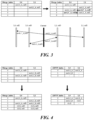
- FIG. 3 illustrates a merge candidates list that includes scaled merge candidates.
- an original merge candidate has mvLX (the motion vector in list X, X can be 0 or 1) and refldxLX (the reference picture index in list X, X can be 0 or 1).
- an original candidate A is a list 0 uni-predicted MV with mvL0_A and reference picture index ref0.
- Candidate A is initially copied to list L1 as having reference picture index ref0'.
- the scaled MV mvL0'_A is calculated by scaling mvL0_A based on ref0 and ref0'.
- a scaled bi-predictive Merge candidate having mvL0_A and ref0 in list L0 and mvL0'_A and ref0' in list L1 is created and added to the merge candidates list.
- a scaled bi-predictive merge candidate which has mvL1'_A and ref1' in List 0 and mvL1_A, ref1 in List 1 is created and added to the merge candidates list.
- zero vector candidates are created by combining zero vectors and reference indices. If a created zero vector candidate is not a duplicate, it is added to the merge/AMVP candidates list.
- FIG. 4 illustrates an example in which zero vector candidates are added to a merge candidates list or an AMVP candidates list.
- TPM Triangular Prediction Mode
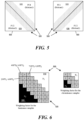
- FIG. 5 illustrates a CU 500 that is coded by triangular prediction mode.
- the CU 500 is split into two triangular units 510 (PU1) and 520 (PU2), in either diagonal or inverse diagonal direction, by a partitioning that is a straight line at an angle or a diagonal line that bifurcates the CU 500.
- the line can be represented with a distance and an angle.
- each unit (for TPM, triangle unit) in the CU is inter-predicted by using its own uni-prediction motion vector and reference frame index which are derived from a candidate list which consist of bi-prediction candidates or uni-prediction candidates.
- the triangular unit 510 is inter-predicted using the first motion information (Motion1) containing motion vector Mv1 and the corresponding reference index
- the triangular unit 520 is inter-predicted using the second motion information (Motion2) containing motion vector Mv2 and the corresponding reference index.
- an overlap prediction region 530 situated over the diagonal boundary between the two triangular partitions is inter-predicted by a weighted sum of the inter-predictions by the first and the second motion information.
- the overlap prediction region 530 may therefore also be referred to as a weighted area or boundary region.
- FIG. 6 illustrates applying an adaptive weighting process to the diagonal edge between the two triangular units 510 and 520 (i.e., the overlap prediction region 530).
- one TPM flag is signaled to indicate whether to enable TPM or not.
- the TPM flag e.g., merge_triangle_flag
- at least three values are encoded into bitstream: First, a splitting direction flag (indicating whether diagonal or inverse diagonal) is encoded using bypass bin. Second, a merge index of PU0 (Idx 0 ) is encoded in the same way as the merge index of regular merge mode. Third, For PU1, instead of encoding the value of its merge index (Idx 1 ) directly, a signaled index (or Idx' 1 ) is signaled since the value of Idx 0 and Idx 1 cannot be equal.
- TPM signaling An example syntax for TPM signaling is provided in the table below. if( merge_triangle_flag[ x0 ][ y0 ] ) ⁇ merge_triangle_split_dir[x0] [y0] u(1) merge_triangle_idx0[x0][y0] ae(v) merge_triangle_idx1[x0][y0] ae(v) ⁇
- Idx' 0 is equal to Idx 0 .
- Idx' 1 is equal to Idx 1 .
- the video codec is not required to compare Idx 0 with Idx 1 before calculating Idx' 0 or Idx' 1 .
- Idx'o is equal to Idx 0
- Idx 1 is equal to Idx 0 + Idx' 1 *sign, where sign is set to be 1 if Idx 1 ⁇ Idx 0 and sign is set to be -1 otherwise (if Idx 1 ⁇ Idx 0 ).
- sign is inferred and doesn't need to be signaled.
- sign can be inferred to be 1 or -1 or can be implicitly decided according to predefined criteria.
- the predefined criteria can depend on the block width or block height or block area or can be interleaving assigned with Idx 0 .
- Idx 0 if Idx 0 is specified in an equation or table, sign is inferred to be 1; otherwise, sign is inferred to be -1.
- Idx' 1 is min (abs(difference of Idx 0 and Idx 1 , N).
- constraints are applied to Idx' 1 , or specifically N when determining Idx' 1 .
- N is the maximum number of TPM candidates.
- N is 2, 3, 4, 5, 6, 7, or 8.
- N can vary with block width or block height or block area.
- the signaled index Idx' 1 can be derived from merge index Idx 0 instead of signaling (e.g., being expressly signaled in a bitstream).
- the offset can be fixed or vary with the block width or block height or block area.
- the offset for a block with area larger than a specific area e.g., 64, 128, 256, 512, 1024, or 2048
- the offset for a block with area smaller than a specific area is larger than the offset for a block with larger area.
- secondary transform is used to further compact the energy of the coefficients and to improve the coding efficiency.
- An encoder performs the primary transform on the pixels of the current block to generate a set of transform coefficients.
- the secondary transform is then performed on the transform coefficients of current block.
- the RST8x8 with a reduction factor of 4 (1/4 size) is applied.
- 64x64 which is conventional 8x8 non-separable transform matrix size
- 16x64 direct matrix is used instead of 64x64, which is conventional 8x8 non-separable transform matrix size.
- the 64 ⁇ 16 inverse RST matrix is used at the decoder side to generate core (primary) transform coefficients in 8 ⁇ 8 top-left regions.
- the forward RST8x8 uses 16 ⁇ 64 (or 16x48 or 8x48 for 8x8 block) matrices.
- 16x16 (or 8x16 for 4x4 block) direct matrix multiplication is applied. So, for a transform block (TB), it produces non-zero coefficients only in the top-left 4 ⁇ 4 region.
- RST zero-out region the first 16 coefficients
- the index IntraPredMode has a range of [-14, 83], which is a transformed mode index used for wide angle intra prediction.
- 1 transform-per-set configuration is used, which greatly reduces memory usage (e.g., by half or SKB).
- a simplification method for RST is applied.
- the simplification method limits worst case number of multiplications per sample to less than or equal to 8. If RST8x8 (or RST4x4) is used, the worst case in terms of multiplication count occurs when all TUs consist of 8x8 TUs (or 4x4 TUs). Therefore, top 8x64 (or 8x48 or 8x16) matrices (in other words, first 8 transform basis vectors from the top in each matrix) are applied to 8x8 TU (or 4x4 TU).
- RST matrices of reduced dimension are used.
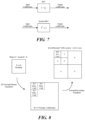
- FIG. 8 illustrates RST with reduced dimensions.
- the figure illustrates an example forward RST8x8 process with 16x48 matrix.
- 16x48 matrices may be applied instead of 16x64 with the same transform set configuration, each of which takes 48 input data from three 4x4 blocks in a top-left 8x8 block excluding right-bottom 4x4 block.
- memory usage for storing all RST matrices may be reduced from 10KB to 8KB with reasonable performance drop.
- RST index is not coded or signaled when any non-zero element is detected within RST zero-out region because it implies that RST was not applied. In such a case, RST index is inferred to be zero.
- affine linear weighted intra prediction is used for predicting the samples of a rectangular block of width W and height H.
- ALWIP may also be referred to as matrix based intra prediction or matrix weighted intra prediction (MIP).
- MIP matrix weighted intra prediction
- ALWIP takes one line of H reconstructed neighbouring boundary samples left of the block and one line of W reconstructed neighbouring boundary samples above the block as input. If the reconstructed samples are unavailable, they are generated as it is done in the conventional intra prediction.
- the generation of the set of prediction samples for ALWIP is based on the following three steps:
- the matrices and offset vectors needed to generate the prediction signal under ALWIP are taken from three sets of matrices (S 0 , S 1 , and S 2 ).
- the set S 1 consists of 8 matrices A 1 i , i ⁇ 0 , ... , 7 , each of which has 16 rows and 8 columns and 8 offset vectors b 1 i , i ⁇ 0 , ... , 7 each of size 16. Matrices and offset vectors of that set are used for blocks of sizes 4x8, 8x4, and 8x8.
- the set S 2 consists of 6 matrices A 2 i , i ⁇ 0 , ... , 5 , each of which has 64 rows and 8 columns and of 6 offset vectors b 2 i , i ⁇ 0 , ... , 5 of size 64. Matrices and offset vectors of that set or parts of these matrices and offset vectors are used for all other block-shapes.
- the total number of multiplications needed in the computation of the matrix vector product is always smaller than or equal to 4 ⁇ W ⁇ H. In other words, at most four multiplications per sample are required for the ALWIP modes.
- the top boundary bdry top and the left boundary bdry left are reduced to smaller boundaries bdry red top and bdry red left .
- bdry red top and bdry red left both consists of 2 samples in the case of a 4x4 block, and both consist of 4 samples in all other cases.
- a reduced prediction signal is generated by matrix vector multiplication.
- a reduced prediction signal pred red is generated.
- the latter signal is a signal on the downsampled block of width W red and height H red .
- b is a vector of size W red ⁇ H red .
- the matrix A and the vector b are taken from one of the sets S 0 , S 1 , S 2 as follows.
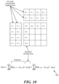
- FIG. 9b illustrates ALWIP for 8 ⁇ 8 blocks.
- ALWIP takes four averages along each axis of the boundary.
- the resulting eight input samples enter the matrix vector multiplication.
- the matrices are taken from the set S 1 ). This yields 16 samples on the odd positions of the prediction block.
- these samples are interpolated vertically by using the reduced top boundary. Horizontal interpolation follows by using the original left boundary. The interpolation process does not require any multiplications in this case. Thus, a total of 2 multiplications per sample is required to calculate ALWIP prediction.
- FIG. 9c illustrates ALWIP for 8x4 blocks.
- ALWIP takes four averages along the horizontal axis of the boundary and the four original boundary values on the left boundary.
- the resulting eight input samples enter the matrix vector multiplication.
- the matrices are taken from the set S 1 . This yields 16 samples on the odd horizontal and each vertical positions of the prediction block.
- After adding an offset these samples are interpolated horizontally by using the original left boundary.
- the interpolation process in this case, does not add any multiplications.
- a total of 4 multiplications per sample are required to calculate ALWIP prediction.
- the procedure is essentially the same and it is easy to check that the number of multiplications per sample is less than four.
- 8•64) ⁇ (W•8) 64/W multiplications per sample are performed to calculate the reduced prediction.
- the number of additional multiplications per sample required for linear interpolation is less than two. Thus, total number of multiplications per sample is less than or equal to four.
- the transform mode for primary transform indicates one transform type for horizontal transform and one transform type for vertical transform.
- the transform mode for primary transform can be implicitly decided or explicitly signaled with a flag and/or an index.
- the transform mode is indicated with an index, and when the index is 0, the transform mode for primary transform is assigned with the default transform mode like DCT-II for both directions.
- the transform mode for primary transform is a specific transform mode (e.g., (DCT-II, DCT-II) or (DST-VII, DST-VII)), secondary transform cannot be applied, or the number of candidates for the secondary transform is reduced to 1 or 2, or the index of secondary transform cannot be equal to the largest index (e.g., 3).
- a specific transform mode e.g., (DCT-II, DCT-II) or (DST-VII, DST-VII)
- secondary transform cannot be applied, or the number of candidates for the secondary transform is reduced to 1 or 2, or the index of secondary transform cannot be equal to the largest index (e.g., 3).
- the secondary transform when the horizontal transform is equal to the vertical transform, the secondary transform cannot be applied, or the number of candidates for the secondary transform is reduced to 1 or 2, or the index of secondary transform cannot be equal to the largest index (e.g., 3).
- secondary transform when secondary transform is applied (e.g. the index for secondary transform is larger than 0), primary transform cannot be used, or the number of candidates for the primary transform is reduced to 1 or 2, or the index of primary transform cannot be equal to the largest index (e.g., 3).
- a default primary transform mode is used and the index of default primary transform mode is set to 0 which means the default primary transform mode for primary transform is DCT-II.
- the index of default primary transform is inferred without signaling.
- the transform types for primary transform will not be further changed with implicit transform type assignment.
- the transforms here may be secondary transform and/or primary transform and/or transform skip mode.
- transform skip or one transform mode for the primary transform is signaled with an index.
- the index for selecting a transform
- the default transform mode e.g. DCT-II for both directions
- transform skip is used.
- the index is larger than 1, one of multiple transform modes (e.g. DST-VII or DCT-VIII used for horizontal and/or vertical transform) can be used.
- an index (from 0 to 2 or 3) is used to select one secondary transform candidate.
- the transforms, including transform skip mode and/or primary transform and/or secondary transform can be signaled with an index. The maximum number of this index is the number of candidates for primary transform + the number of candidates for secondary transform + 1 for transform skip mode.
- the method for efficient signaling of multiple transforms is used to determine a signaling order. For example, there are 4 candidate primary transform combinations (one default transform + different combinations), 4 candidate secondary transform combination (no secondary transform + 2 or 3 candidates), and transform skip mode.
- the method for efficient signaling of multiple transform can be used for any subset of the total combinations to generate the corresponding costs and the signaling can be changed accordingly.
- the transforms here (the transforms being signaled) includes transform skip mode and the default transform mode for the primary transform. If the cost of the transform skip mode is smaller than the cost of the default transform mode, the codeword length of transform skip mode is shorter than the codeword length of the default transform mode.
- the index for transform skip mode is assigned with 0 and the index for the default transform mode is assigned with 1.
- the transform here (the transform being signaled) is the transform skip mode. If the cost of the transform skip mode is smaller than a particular threshold, the codeword length of the transform skip mode is shorter than other transforms for the primary transform.
- the threshold can vary with the block width or block height or block area.
- the prediction mode for a CU can be indicated with an index.
- the prediction mode may be inter mode, intra mode, intra-block copy mode (IBC mode), and/or a new added combined mode.
- the context for this index can be decided independently of the information from neighboring blocks.
- the context for the first bin or the bin (to decide whether the prediction mode is intra mode or not) can be decided by counting the number of intra-coded neighboring blocks. For example, the neighboring blocks contain left and/or above, one 4x4 block from left and/or one 4x4 block from above, denoted as A 1 and/or B 1 , respectively.
- the neighboring blocks contain left (denoted as A 1 ), above (denoted as B 1 ), above-left (denoted as B 2 ), left-bottom (denoted as A 0 ), and/or above-right (denoted as B 0 ).
- neighboring blocks contain the 4x4 blocks in neighboring 4x8, 8x4, or 8x8 area such as left (denoted as A 1 ), left-related (denoted as A 3 ), above (denoted as B 1 ), above-related (denoted as B x , where x can be 0, 2, 3, 4, 5, 6, 7, 8, or 9), and/or left-bottom (denoted as A 0 ).
- an additional flag is signaled to indicate if the combined inter/intra prediction (CIIP) mode is applied to the current CU.
- CIIP inter/intra prediction
- an intra prediction mode is first derived from two additional syntax elements. Up to four possible intra prediction modes can be used: DC, planar, horizontal, or vertical. Then, the inter prediction and intra prediction signals are derived using regular intra and inter decoding processes. Finally, weighted averaging of the inter and intra prediction signals is performed to obtain the CIIP prediction.
- the CIIP mode is simplified by reducing the number of intra modes allowed from 4 to only 1, i.e., planar mode, and the CIIP most probable mode (MPM) list construction is therefore also removed.
- MPM most probable mode
- the weight for intra and inter predicted samples are adaptively selected based on the number of neighboring intra-coded blocks.
- the (wIntra, wInter) weights are adaptively set as follows. If both top and left neighbors are intra-coded, (wIntra, wInter) is set equal to (3,1). Otherwise, if one of these blocks is intra-coded, these weights are identical, i.e., (2,2), else the weights are set equal to (1,3).
- a neighbor-based weighting method for CIIP and the weight for intra prediction and the weight for inter prediction are denoted as (wintra, winter).
- this neighbor-based weighting method both of the left and above neighboring block are used to decide the weights for intra and inter prediction when planar mode is selected to be the intra prediction mode for CIIP.
- the weights used for combining intra prediction and inter prediction can be selected from any subset of the weighting pool according to a set of weight-combination settings.
- the intra prediction multiplied by wintra is added with the inter prediction multiplied by winter and then a right-shift N is applied.
- the number of wintra and winter may be changed according to N.
- any subset of ⁇ above, left, above-left, above-right, bottom, bottom-left ⁇ can be used to decide the weights for CIIP according to a set of block-position settings.
- combi, comb2, and comb3 can be equal to the settings described above, or can be set as any subset, proposed in weight-combination settings, with any order.
- comb1, comb2, and comb3 can be (1, 3), (2, 2), and (3, 1), respectively, or can be (3, 1), (2, 2), and (1, 3), respectively, or any other possible ordering.
- only left block is used (to decide the weights for CIIP). For example, in some embodiments, if both top and left neighbors are intra-coded, (wintra, wInter) is set equal to comb1; otherwise, if one of these blocks is intra-coded, these weights are identical, i.e., comb2, else the weights are set equal to comb3. In some embodiments, if the above block is not in the same CTU for the current block, and if left neighbor is intra-coded, (wintra, wInter) is set equal to comb1; otherwise, these weights are identical, i.e., comb2, or comb3. In some embodiments, at least left block is used (to decide the weights for CIIP).
- one constraint may need.
- the above block should not be treated as an intra mode. For example, in some embodiments, if both top and left neighbors are intra-coded, (wintra, wInter) is set equal to comb1; otherwise, if one of these blocks is intra-coded, these weights are identical, i.e., comb2, else the weights are set equal to comb3. If the above block is not in the same CTU for the current block, (wintra, wInter) does not equal to comb1. When the above block is not in the same CTU for the current block, the above block should not be considered.
- both top and left neighbors are intra-coded, (wintra, wInter) is set equal to comb1; otherwise, if one of these blocks is intra-coded, these weights are identical for intra and inter weights, i.e., comb2, else the weights are set equal to comb3. If the above block is not in the same CTU for the current block, and if the left neighbor is intra-coded, (wintra, wInter) is set equal to comb1; otherwise, these weights are identical for intra and inter weights, i.e., comb2, or comb3.
- the CIIP weighting (wintra, winter) for a CU can use a unified method with how to decide the context for other prediction modes.
- the CIIP weighting can be decided independent of the information from neighboring blocks.
- the CIIP weighting can be decided by counting the number of intra-coded neighboring blocks.
- the neighboring blocks contain left and/or above, one 4x4 block from left and/or one 4x4 block from above, denoted as A 1 and/or B 1 , respectively.
- the neighboring blocks contain left (denoted as A 1 ), above (denoted as B 1 ), above-left (denoted as B 2 ), left-bottom (denoted as A 0 ), and/or above-right (denoted as B 0 ).
- neighboring blocks contain the 4x4 blocks in neighboring 4x8, 8x4, or 8x8 area such as left (denoted as A 1 ), left-related (denoted as A 3 ), above (denoted as B 1 ), above-related (denoted as B x , where x can be 0, 2, 3, 4, 5, 6, 7, 8, or 9), and/or left-bottom (denoted as A 0 ).
- the CIIP weighting can depend on the neighboring blocks from any one or any combination of ⁇ left, above, right, bottom, above-right, above-left ⁇ .
- the neighboring blocks from left and/or above can be used.
- the CIIP weighting cannot reference the cross-CTU-row information. For example, only the neighboring blocks from left (A 1 ) and/or left-related (A 3 ) can be used (since A 1 and A 3 are in the same CTU-row as the current block).
- the neighboring blocks form left (A 1 ) and/or left-related (A 3 ), and/or the neighboring blocks from above (B 1 ) in the same CTU, and/or above-related (e.g. B x , where x can be 0, 2, 3, 4, 5, 6, 7, 8, or 9) in the same CTU can be used.
- any combination of above can be applied. Any variances of above can be implicitly decided with the block width or block height or block area, or explicitly decided by a flag signaled at CU, CTU, slice, tile, tile group, SPS, or PPS level.
- any of the foregoing proposed methods can be implemented in encoders and/or decoders.
- any of the proposed methods can be implemented in an inter/intra/transform coding module of an encoder, a motion compensation module, a merge candidate derivation module of a decoder.
- any of the proposed methods can be implemented as a circuit coupled to the inter/intra/transform coding module of an encoder and/or motion compensation module, a merge candidate derivation module of the decoder.
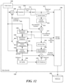
- FIG. 12 illustrates an example video encoder 1200 that implements various primary transforms, secondary transforms, and/or prediction modes.
- the video encoder 1200 receives input video signal from a video source 1205 and encodes the signal into bitstream 1295.
- the video encoder 1200 has several components or modules for encoding the signal from the video source 1205, at least including some components selected from a transform module 1210, a quantization module 1211, an inverse quantization module 1214, an inverse transform module 1215, an intra-picture estimation module 1220, an intra-prediction module 1225, a motion compensation module 1230, a motion estimation module 1235, an in-loop filter 1245, a reconstructed picture buffer 1250, a MV buffer 1265, and a MV prediction module 1275, and an entropy encoder 1290.
- the motion compensation module 1230 and the motion estimation module 1235 are part of an inter-prediction module 1240.
- the modules 1210 - 1290 are modules of software instructions being executed by one or more processing units (e.g., a processor) of a computing device or electronic apparatus. In some embodiments, the modules 1210 - 1290 are modules of hardware circuits implemented by one or more integrated circuits (ICs) of an electronic apparatus. Though the modules 1210 - 1290 are illustrated as being separate modules, some of the modules can be combined into a single module.
- processing units e.g., a processor
- ICs integrated circuits
- the video source 1205 provides a raw video signal that presents pixel data of each video frame without compression.
- a subtractor 1208 computes the difference between the raw video pixel data of the video source 1205 and the predicted pixel data 1213 from the motion compensation module 1230 or intra-prediction module 1225.
- the transform module 1210 converts the difference (or the residual pixel data or residual signal 1209) into transform coefficients (e.g., by performing Discrete Cosine Transform, or DCT).
- the quantization module 1211 quantizes the transform coefficients into quantized data (or quantized coefficients) 1212, which is encoded into the bitstream 1295 by the entropy encoder 1290.
- the motion estimation module 1235 performs inter-prediction by producing MVs to reference pixel data of previously decoded frames stored in the reconstructed picture buffer 1250. These MVs are provided to the motion compensation module 1230 to produce predicted pixel data.
- the video encoder 1200 uses MV prediction to generate predicted MVs, and the difference between the MVs used for motion compensation and the predicted MVs is encoded as residual motion data and stored in the bitstream 1295.
- the MV prediction module 1275 generates the predicted MVs based on reference MVs that were generated for encoding previously video frames, i.e., the motion compensation MVs that were used to perform motion compensation.
- the MV prediction module 1275 retrieves reference MVs from previous video frames from the MV buffer 1265.
- the video encoder 1200 stores the MVs generated for the current video frame in the MV buffer 1265 as reference MVs for generating predicted MVs.
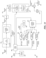
- FIG. 13 illustrates portions of the encoder 1200 that enables and disables various primary transforms, secondary transform, and/or prediction modes. Specifically, for each block of pixels, the encoder 1200 determines whether to perform a particular type of secondary transform (e.g., RST or LFNST), whether to perform a particular type of primary transform (e.g., DCT-II), whether to perform a particular type of prediction (e.g. ALWIP, TPM, or CIIP), and how to signal in the bitstream 1295 which modes are enabled.
- a particular type of secondary transform e.g., RST or LFNST
- a particular type of primary transform e.g., DCT-II
- a particular type of prediction e.g. ALWIP, TPM, or CIIP
- the MV buffer 1265 provides the merge candidates to the motion compensation modules 1230 and/or 1330.
- the MV buffer 1265 also stores the motion information and the mode directions used to encode the current block for use by subsequent blocks.
- the merge candidates may be altered, expanded, and/or refined by a MV refinement module 1365.
- the encoder 1200 includes a coding control module 1300.
- the coding control module 1300 controls the operation of the MV refinement module 1365.
- the coding control module 1300 also controls the transform and/or prediction operations of the encoder. For example, the coding control module 1300 determines whether to perform secondary transform and which type of secondary transform to perform (e.g., RST). For another example, the coding control module 1300 determines which type of primary transform to perform (e.g., DCT-II).
- the coding control module 1300 controls the transform operations (primary and/or secondary) of the transform module 1210 and the inverse transform operations (primary and/or secondary) of the inverse transform module 1215
- the coding control module 1300 may enable the intra-prediction module 1225, the motion compensation module 1230, and/or the second motion compensation module 1330 to implement various prediction modes. Specifically, the coding control module 1300 may enable the motion compensation module 1230 and/or the second motion compensation module 1330 to implement TPM. The coding control module 1300 may enable the motion compensation module 1230 and/or the intra-prediction module 1225 to implement CIIP. The coding control module 1300 may also enable the combined prediction module 1310 to adopt different weighting schemes when combining prediction signals from intra-picture prediction module 1225, the motion compensation module 1230, and/or the second motion compensation module 1330, such as for the overlap prediction region 530 situated over the diagonal or straight line boundary of TPM.
- the encoder receives (at block 1410) raw pixel data for a block of pixels to be encoded as a current block of a current picture of a video into a bitstream.
- the encoder determines (at block 1411) whether the block is coded by inter-prediction. If not, the process proceeds to block 1460. If so, the process determines (at block 1412) if the block is coded by TPM. If so, the process proceeds to block 1420. If not, the encoder encodes (at block 1495) the current block by using a prediction based on one motion candidate.
- the encoder uses (at block 1420) a first merge index to select a first motion candidate and a second merge index to select a second motion candidate.
- the encoder computes (at block 1430) (i) a first prediction based on the first motion candidate for the current block and (ii) a second prediction based on the second motion candidate for the current block.
- the current block is partitioned into the first and second units along a straight line at an angle bifurcating the current block for TPM mode.
- the first prediction affects the first unit
- the second prediction affects the second unit
- both the first and second predictions affect the overlap prediction region.
- the encoder encodes (at block 1440) into the bitstream a first signaled index and a second signaled index that are determined from the first and second merge indices.
- the second signaled index is determined based on a comparison between the first merge index and the second merge index.
- the first signaled index is same as the first merge index but the second signaled index and the second merge index may be different.
- the second signaled index is same as the second merge index but the first signaled index and the first merge index may be different.
- the second merge index is computed as a sum or a difference of the first merge index and the second signaled index.
- the second merge index is computed based on a sign bit that is signaled in the bitstream.
- the encoder encodes (at block 1450) the current block into a bitstream by using the computed first and second predictions.
- the encoder generates (at block 1460) a set of prediction samples by intra prediction. For example, for ALWIP, by performing averaging, matrix vector multiplication, and/or linear interpolation based on pixels of the current block to generate a set of prediction samples of the current block, in other words, performing ALWIP prediction as described in Section IV above.
- whether secondary transform and ALWIP are both performed is conditioned upon whether size, width, or height of the current block is greater or less than a threshold (e.g., before performing the secondary transform, the encoder determines that a size/width/height of the current block is greater than or equal to a first threshold and/or less than second threshold, or/and determines that an index of the secondary transform is larger than an index threshold.)
- the encoder performs (at block 1480) a secondary transform on the first set of transform coefficients to generate a second set of transform coefficients.
- the encoder enables the primary transform by selecting a default candidate when a secondary transform is applied to the current block.
- the encoder then encodes the current block by performing transform operations on the received pixel data according to the enabled primary and secondary transforms to generate a set of transform coefficients.
- the modules 1510 - 1590 are modules of software instructions being executed by one or more processing units (e.g., a processor) of a computing device. In some embodiments, the modules 1510 - 1590 are modules of hardware circuits implemented by one or more ICs of an electronic apparatus. Though the modules 1510 - 1590 are illustrated as being separate modules, some of the modules can be combined into a single module.
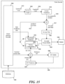
- the parser 1590 receives the bitstream 1595 and performs initial parsing according to the syntax defined by a video-coding or image-coding standard.
- the parsed syntax element includes various header elements, flags, as well as quantized data (or quantized coefficients) 1512.
- the parser 1590 parses out the various syntax elements by using entropy-coding techniques such as context-adaptive binary arithmetic coding (CABAC) or Huffman encoding.
- CABAC context-adaptive binary arithmetic coding
- Huffman encoding Huffman encoding
- the inverse quantization module 1505 de-quantizes the quantized data (or quantized coefficients) 1512 to obtain transform coefficients, and the inverse transform module 1510 performs inverse transform on the transform coefficients 1516 to produce reconstructed residual signal 1519.
- the reconstructed residual signal 1519 is added with predicted pixel data 1513 from the intra-prediction module 1525 or the motion compensation module 1530 to produce decoded pixel data 1517.
- the decoded pixels data are filtered by the in-loop filter 1545 and stored in the decoded picture buffer 1550.
- the decoded picture buffer 1550 is a storage external to the video decoder 1500.
- the decoded picture buffer 1550 is a storage internal to the video decoder 1500.
- the intra-prediction module 1525 receives intra-prediction data from bitstream 1595 and according to which, produces the predicted pixel data 1513 from the decoded pixel data 1517 stored in the decoded picture buffer 1550.
- the decoded pixel data 1517 is also stored in a line buffer (not illustrated) for intra-picture prediction and spatial MV prediction.
- the content of the decoded picture buffer 1550 is used for display.
- a display device 1555 either retrieves the content of the decoded picture buffer 1550 for display directly, or retrieves the content of the decoded picture buffer to a display buffer.
- the display device receives pixel values from the decoded picture buffer 1550 through a pixel transport.
- the motion compensation module 1530 produces predicted pixel data 1513 from the decoded pixel data 1517 stored in the decoded picture buffer 1550 according to motion compensation MVs (MC MVs). These motion compensation MVs are decoded by adding the residual motion data received from the bitstream 1595 with predicted MVs received from the MV prediction module 1575.
- MC MVs motion compensation MVs
- the MV prediction module 1575 generates the predicted MVs based on reference MVs that were generated for decoding previous video frames, e.g., the motion compensation MVs that were used to perform motion compensation.
- the MV prediction module 1575 retrieves the reference MVs of previous video frames from the MV buffer 1565.
- the video decoder 1500 stores the motion compensation MVs generated for decoding the current video frame in the MV buffer 1565 as reference MVs for producing predicted MVs.
- the in-loop filter 1545 performs filtering or smoothing operations on the decoded pixel data 1517 to reduce the artifacts of coding, particularly at boundaries of pixel blocks.
- the filtering operation performed includes sample adaptive offset (SAO).
- the filtering operations include adaptive loop filter (ALF).
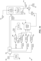
- FIG. 16 illustrates portions of the decoder 1500 that enables and disables various primary transforms, secondary transform, and/or prediction modes. Specifically, for each block of pixels, the decoder 1500 determines whether to perform a particular type of secondary transform (e.g., RST), whether to perform a particular type of primary transform (e.g., DCT-II), whether to perform a particular type of prediction (e.g. ALWIP, TPM, or CIIP), and how to determine which modes are enabled based on content of the bitstream 1595.
- a particular type of secondary transform e.g., RST
- DCT-II DCT-II
- prediction e.g. ALWIP, TPM, or CIIP
- the MV buffer 1565 provides the merge candidates to the motion compensation modules 1530 and/or 1630.
- the MV buffer 1565 also stores the motion information and the mode directions used to encode the current block for use by subsequent blocks.
- the merge candidates may be altered, expanded, and/or refined by a MV refinement module 1665.
- the coding control module 1600 may enable the intra-prediction module 1525, the motion compensation module 1530, and/or the second motion compensation module 1630 to implement various prediction modes. Specifically, the coding control module 1600 may enable the motion compensation module 1530 and/or the second motion compensation module 1630 to implement TPM. The coding control module 1600 may enable the motion compensation module 1530 and/or the intra-prediction module 1525 to implement CIIP. The coding control module 1600 may also enable the combined prediction module 1610 to adopt different weighting schemes when combining prediction signals from intra-picture prediction module 1525, the motion compensation module 1530, and/or the second motion compensation module 1630, such as for the overlap prediction region 530 situated over the diagonal straight line boundary of TPM.
- the coding control module 1600 may also be used to implement or define interactions between the various transform and prediction modes. For example, in some embodiments, the coding control module 1600 may enable both ALWIP operations and RST operations for coding the current block. The coding control module 1600 may further condition the enabling of both ALWIP and RST upon a size, width, or height of the current block (e.g., RST can be performed in an ALWIP block only if the block width and/or height is larger than or equal to a certain threshold size like 16.) As another example, the coding control module 1600 may select a default primary transform mode such as DCT-II for both horizontal and vertical transform whenever a secondary transform mode is enabled (e.g., having a non-zero index.) The coding control module 1600 may also be used to receive parameters or settings (e.g., merge index) from the bitstream 1595.
- parameters or settings e.g., merge index
- the coding control module 1600 may receive two signaled indices (Idx'1 and Idx'0) from the bitstream 1595 as syntax elements rather than the actual merge indices (Idx0 and Idx1) used to encode the two PUs of the current block.
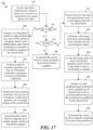
- FIG. 17 conceptually illustrates a process 1700 for decoding a block of pixels by enabling certain primary transform, secondary transform, and/or prediction modes.
- one or more processing units e.g., a processor
- a computing device implementing the decoder 1500 performs the process 1700 by executing instructions stored in a computer readable medium.
- an electronic apparatus implementing the decoder 1500 performs the process 1700.
- the decoder receives (at block 1710) data from a bitstream for a block of pixels to be decoded as a current block of a current picture of a video.
- the decoder determines (at block 1711) whether the block is coded by inter-prediction. If no, the process proceeds to block 1760. If so, the process determines (at block 1712) if the block is coded by TPM. If so, the process proceeds to block 1715. If not, the decoder decodes (at block 1795) the current block by using a prediction based on one motion candidate.
- the decoder receives (at block 1715) from the bitstream a first signaled index and a second signaled index for the current block.
- the decoder determines (at block 1720) a first merge index and a second merge index from the first and second signaled indices.
- the second signaled index is determined based on a comparison between the first merge index and the second merge index.
- the first signaled index is same as the first merge index but the second signaled index and the second merge index may be different.
- the second signaled index is same as the second merge index but the first signaled index and the first merge index may be different.
- the second merge index is computed as a sum or a difference of the first merge index and the second signaled index. In some embodiments, the second merge index is computed based on a sign bit that is signaled in the bitstream. In some embodiments, the second merge index is computed based on a sign bit that is inferred based on the first merge index.
- the decoder uses (at block 1730) the first merge index to select a first motion candidate and the second merge index to select a second motion candidate.
- the decoder computes (at block 1740) (i) a first prediction based on the first motion candidate for the current block and (ii) a second prediction based on the second motion candidate for the current block.
- the current block is partitioned into the first and second units along a straight line at an angle bifurcating the current block for TPM mode.
- the first prediction affects the first unit
- the second prediction affects the second unit
- both the first and second predictions affect the overlap prediction region.
- the decoder reconstructs (at block 1750) the current block by using the computed first and second predictions.
- the default primary transform is discrete cosine transform type II (DCT-II).
- the secondary transform is reduced secondary transform (RST) that maps an N dimensional vector to an R dimensional vector in a different space, wherein R is less than N.
- the secondary transform is selected from four or less candidate secondary transforms.
- the primary transform is selected from only one primary transform candidate (e.g. the default primary transform mode such as DCT-II for horizontal and vertical transform) when the secondary transform is enabled.
- the index of the only primary transform candidate is less than three, e.g., zero. For example, when secondary transform is applied (e.g. the index for secondary transform is larger than 0), only one primary transform mode can be used and the index of primary transform is set to 0 which means the transform mode for primary transform is DCT-II.
- the decoder reconstructs (at block 1790) the current block by using the set of residual samples and the set of prediction samples.
- Computer readable storage medium also referred to as computer readable medium.
- these instructions are executed by one or more computational or processing unit(s) (e.g., one or more processors, cores of processors, or other processing units), they cause the processing unit(s) to perform the actions indicated in the instructions.
- computational or processing unit(s) e.g., one or more processors, cores of processors, or other processing units
- Examples of computer readable media include, but are not limited to, CD-ROMs, flash drives, random-access memory (RAM) chips, hard drives, erasable programmable read only memories (EPROMs), electrically erasable programmable read-only memories (EEPROMs), etc.
- the computer readable media does not include carrier waves and electronic signals passing wirelessly or over wired connections.
- the term "software” is meant to include firmware residing in read-only memory or applications stored in magnetic storage which can be read into memory for processing by a processor.
- multiple software inventions can be implemented as sub-parts of a larger program while remaining distinct software inventions.
- multiple software inventions can also be implemented as separate programs.
- any combination of separate programs that together implement a software invention described here is within the scope of the present disclosure.
- the software programs when installed to operate on one or more electronic systems, define one or more specific machine implementations that execute and perform the operations of the software programs.
- the processing unit(s) 1810 retrieves instructions to execute and data to process in order to execute the processes of the present disclosure.
- the processing unit(s) may be a single processor or a multi-core processor in different embodiments. Some instructions are passed to and executed by the GPU 1815.
- the GPU 1815 can offload various computations or complement the image processing provided by the processing unit(s) 1810.
- the read-only-memory (ROM) 1830 stores static data and instructions that are used by the processing unit(s) 1810 and other modules of the electronic system.
- the permanent storage device 1835 is a read-and-write memory device. This device is a non-volatile memory unit that stores instructions and data even when the electronic system 1800 is off. Some embodiments of the present disclosure use a mass-storage device (such as a magnetic or optical disk and its corresponding disk drive) as the permanent storage device 1835.
- bus 1805 also couples electronic system 1800 to a network 1825 through a network adapter (not shown).
- the computer can be a part of a network of computers (such as a local area network (“LAN”), a wide area network (“WAN”), or an Intranet, or a network of networks, such as the Internet. Any or all components of electronic system 1800 may be used in conjunction with the present disclosure.
- the computer-readable media may store a computer program that is executable by at least one processing unit and includes sets of instructions for performing various operations.
- Examples of computer programs or computer code include machine code, such as is produced by a compiler, and files including higher-level code that are executed by a computer, an electronic component, or a microprocessor using an interpreter.
- any two components so associated can also be viewed as being “operably connected”, or “operably coupled”, to each other to achieve the desired functionality, and any two components capable of being so associated can also be viewed as being “operably couplable”, to each other to achieve the desired functionality.
- operably couplable include but are not limited to physically mateable and/or physically interacting components and/or wirelessly interactable and/or wirelessly interacting components and/or logically interacting and/or logically interactable components.
Landscapes
- Engineering & Computer Science (AREA)
- Multimedia (AREA)
- Signal Processing (AREA)
- Physics & Mathematics (AREA)
- Discrete Mathematics (AREA)
- General Physics & Mathematics (AREA)
- Compression Or Coding Systems Of Tv Signals (AREA)
Applications Claiming Priority (4)
| Application Number | Priority Date | Filing Date | Title |
|---|---|---|---|
| US201962828567P | 2019-04-03 | 2019-04-03 | |
| US16/836,904 US11616966B2 (en) | 2019-04-03 | 2020-03-31 | Interaction between core transform and secondary transform |
| EP20782513.4A EP3949417A4 (de) | 2019-04-03 | 2020-04-03 | Interaktion zwischen kerntransformation und sekundärtransformation |
| PCT/CN2020/083090 WO2020200298A1 (en) | 2019-04-03 | 2020-04-03 | Interaction between core transform and secondary transform |
Related Parent Applications (1)
| Application Number | Title | Priority Date | Filing Date |
|---|---|---|---|
| EP20782513.4A Division EP3949417A4 (de) | 2019-04-03 | 2020-04-03 | Interaktion zwischen kerntransformation und sekundärtransformation |
Publications (2)
| Publication Number | Publication Date |
|---|---|
| EP4290863A2 true EP4290863A2 (de) | 2023-12-13 |
| EP4290863A3 EP4290863A3 (de) | 2024-02-21 |
Family
ID=72663352
Family Applications (2)
| Application Number | Title | Priority Date | Filing Date |
|---|---|---|---|
| EP23206148.1A Pending EP4290863A3 (de) | 2019-04-03 | 2020-04-03 | Interaktion zwischen kerntransformation und sekundärtransformation |
| EP20782513.4A Withdrawn EP3949417A4 (de) | 2019-04-03 | 2020-04-03 | Interaktion zwischen kerntransformation und sekundärtransformation |
Family Applications After (1)
| Application Number | Title | Priority Date | Filing Date |
|---|---|---|---|
| EP20782513.4A Withdrawn EP3949417A4 (de) | 2019-04-03 | 2020-04-03 | Interaktion zwischen kerntransformation und sekundärtransformation |
Country Status (5)
| Country | Link |
|---|---|
| US (1) | US11616966B2 (de) |
| EP (2) | EP4290863A3 (de) |
| CN (1) | CN113661710B (de) |
| TW (1) | TWI749503B (de) |
| WO (1) | WO2020200298A1 (de) |
Families Citing this family (41)
| Publication number | Priority date | Publication date | Assignee | Title |
|---|---|---|---|---|
| CA3175176C (en) * | 2017-08-04 | 2024-07-02 | Guangdong Oppo Mobile Telecommunications Corp., Ltd. | METHOD AND APPARATUS FOR CONFIGURING A TRANSFORMER FOR VIDEO COMPRESSION |
| WO2019194503A1 (ko) * | 2018-04-01 | 2019-10-10 | 엘지전자 주식회사 | 분할된 블록에 2차 변환을 적용하여 비디오 신호를 처리하는 방법 및 장치 |
| US11178396B2 (en) | 2018-11-14 | 2021-11-16 | Tencent America LLC | Constrained intra prediction and unified most probable mode list generation |
| US11616966B2 (en) * | 2019-04-03 | 2023-03-28 | Mediatek Inc. | Interaction between core transform and secondary transform |
| US11172211B2 (en) * | 2019-04-04 | 2021-11-09 | Tencent America LLC | Method and apparatus for video coding |
| US11134257B2 (en) * | 2019-04-04 | 2021-09-28 | Tencent America LLC | Simplified signaling method for affine linear weighted intra prediction mode |
| US11240534B2 (en) * | 2019-04-05 | 2022-02-01 | Qualcomm Incorporated | Extended multiple transform selection for video coding |
| EP3949423A4 (de) | 2019-04-16 | 2023-04-12 | HFI Innovation Inc. | Verfahren und vorrichtungen zur codierung von videodaten mit sekundärtransformation |
| KR102845344B1 (ko) | 2019-04-16 | 2025-08-11 | 엘지전자 주식회사 | 영상 코딩에서 매트릭스 기반의 인트라 예측을 위한 변환 |
| WO2020213946A1 (ko) * | 2019-04-16 | 2020-10-22 | 엘지전자 주식회사 | 변환 인덱스를 이용하는 영상 코딩 |
| CN118175312A (zh) * | 2019-04-16 | 2024-06-11 | Lg电子株式会社 | 解码和编码设备及发送用于图像的数据的设备 |
| US11943476B2 (en) * | 2019-04-16 | 2024-03-26 | Hfi Innovation Inc. | Methods and apparatuses for coding video data with adaptive secondary transform signaling |
| KR20250078609A (ko) * | 2019-05-08 | 2025-06-02 | 엘지전자 주식회사 | Mip 및 lfnst를 수행하는 영상 부호화/복호화 방법, 장치 및 비트스트림을 전송하는 방법 |
| US11363284B2 (en) * | 2019-05-09 | 2022-06-14 | Qualcomm Incorporated | Upsampling in affine linear weighted intra prediction |
| US11277637B2 (en) * | 2019-05-09 | 2022-03-15 | Qualcomm Incorporated | Reference sampling for matrix intra prediction mode |
| WO2020228670A1 (en) * | 2019-05-10 | 2020-11-19 | Beijing Bytedance Network Technology Co., Ltd. | Luma based secondary transform matrix selection for video processing |
| CN117354521A (zh) | 2019-06-07 | 2024-01-05 | 北京字节跳动网络技术有限公司 | 视频比特流中的简化二次变换的有条件信令 |
| JP7456441B2 (ja) * | 2019-06-11 | 2024-03-27 | ソニーグループ株式会社 | 画像処理装置及び画像処理方法 |
| US11197025B2 (en) | 2019-06-21 | 2021-12-07 | Qualcomm Incorporated | Signaling of matrix intra prediction parameters in video coding |
| CN119402667B (zh) * | 2019-07-07 | 2026-02-03 | Oppo广东移动通信有限公司 | 图像预测方法、编码器、解码器以及存储介质 |
| CN114208183B (zh) | 2019-08-03 | 2025-01-10 | 北京字节跳动网络技术有限公司 | 视频的缩减二次变换中基于位置的模式导出 |
| WO2021032045A1 (en) * | 2019-08-17 | 2021-02-25 | Beijing Bytedance Network Technology Co., Ltd. | Context modeling of side information for reduced secondary transforms in video |
| KR20220038128A (ko) * | 2019-08-22 | 2022-03-25 | 엘지전자 주식회사 | 인트라 예측 장치 및 방법 |
| EP4035360A1 (de) | 2019-09-24 | 2022-08-03 | Fraunhofer-Gesellschaft zur Förderung der angewandten Forschung e.V. | Effiziente implementierung einer matrixbasierten intraprädiktion |
| WO2021173552A1 (en) | 2020-02-24 | 2021-09-02 | Bytedance Inc. | Interaction between subpicture and tile row signaling |
| EP4097980A4 (de) * | 2020-03-03 | 2023-04-19 | ByteDance Inc. | Nichttrennbare niederfrequente transformationssignalisierung in der videocodierung |
| CN115462071B (zh) | 2020-03-11 | 2025-03-25 | 抖音视界有限公司 | 处理视频数据的方法及装置、介质、存储比特流的方法 |
| WO2021244419A1 (en) | 2020-05-31 | 2021-12-09 | Beijing Bytedance Network Technology Co., Ltd. | Constraint signaling using general constraint information syntax element |
| EP4173294A1 (de) * | 2020-06-30 | 2023-05-03 | InterDigital VC Holdings France, SAS | Verbesserungen im hybriden texturpartikelcodierungsmodus |
| US20220150518A1 (en) * | 2020-11-11 | 2022-05-12 | Tencent America LLC | Method and apparatus for video coding |
| CN115633172A (zh) * | 2020-12-06 | 2023-01-20 | 浙江大华技术股份有限公司 | 基于ibc模式编码方法、电子设备及存储介质 |
| US12375663B2 (en) * | 2021-06-27 | 2025-07-29 | Alibaba Innovation Private Limited | Methods and systems for performing combined inter and intra prediction |
| EP4391530A4 (de) * | 2021-08-18 | 2025-07-30 | Lg Electronics Inc | Bildcodierungs-/-decodierungsverfahren und vorrichtung zur durchführung von referenzprobenfilterung auf basis eines intraprädiktionsmodus und verfahren zur bitstromübertragung |
| CN116325750A (zh) * | 2021-08-30 | 2023-06-23 | 腾讯美国有限责任公司 | 用于具有自适应内核选项的二次变换的方法和装置 |
| WO2023038447A1 (ko) * | 2021-09-08 | 2023-03-16 | 현대자동차주식회사 | 비디오 부호화/복호화 방법 및 장치 |
| US12126794B2 (en) * | 2021-09-30 | 2024-10-22 | Tencent America LLC | Adaptive transforms for compound inter-intra prediction modes |
| US12114014B2 (en) | 2021-10-01 | 2024-10-08 | Tencent America LLC | Secondary transforms for compound inter-intra prediction modes |
| EP4437729A4 (de) * | 2021-11-22 | 2025-11-26 | Beijing Dajia Internet Information Tech Co Ltd | Planarmodusverbesserung zur intraprädiktion |
| WO2023131298A1 (en) * | 2022-01-07 | 2023-07-13 | Mediatek Inc. | Boundary matching for video coding |
| CN118511533A (zh) * | 2022-01-10 | 2024-08-16 | 联发科技股份有限公司 | 在视频编解码系统中使用边界匹配进行重叠块运动补偿的方法和装置 |
| US20250324066A1 (en) * | 2024-04-12 | 2025-10-16 | Tencent America LLC | Selective transform set in video coding |
Family Cites Families (56)
| Publication number | Priority date | Publication date | Assignee | Title |
|---|---|---|---|---|
| EP2081386A1 (de) * | 2008-01-18 | 2009-07-22 | Panasonic Corporation | Hochpräzise Randvorhersage zur Intrakodierung |
| US20110090952A1 (en) * | 2009-10-21 | 2011-04-21 | Cohen Robert A | Directional Transforms for Video and Image Coding |
| KR101484281B1 (ko) * | 2010-07-09 | 2015-01-21 | 삼성전자주식회사 | 블록 병합을 이용한 비디오 부호화 방법 및 그 장치, 블록 병합을 이용한 비디오 복호화 방법 및 그 장치 |
| US9258573B2 (en) * | 2010-12-07 | 2016-02-09 | Panasonic Intellectual Property Corporation Of America | Pixel adaptive intra smoothing |
| KR20130050403A (ko) * | 2011-11-07 | 2013-05-16 | 오수미 | 인터 모드에서의 복원 블록 생성 방법 |
| CN103024389B (zh) | 2012-12-24 | 2015-08-12 | 芯原微电子(北京)有限公司 | 一种用于hevc的解码装置和方法 |
| CN103561263B (zh) | 2013-11-06 | 2016-08-24 | 北京牡丹电子集团有限责任公司数字电视技术中心 | 基于运动矢量约束和加权运动矢量的运动补偿预测方法 |
| BR112017010468B1 (pt) * | 2014-11-18 | 2024-01-02 | Hfi Innovation Inc | Método de decodificação de vídeo para blocos codificados no modo de interpredição e método de codificação de vídeo para blocos codificados no modo de interpredição |
| EP3355578B1 (de) * | 2015-09-24 | 2020-12-09 | LG Electronics Inc. | Bewegungsvektorprädiktorenherleitung und kandidatenlistenkonstruktion |
| US10491922B2 (en) | 2015-09-29 | 2019-11-26 | Qualcomm Incorporated | Non-separable secondary transform for video coding |
| EP4568242A1 (de) * | 2016-05-13 | 2025-06-11 | Sony Group Corporation | Bildverarbeitungsvorrichtung und -verfahren |
| US10728552B2 (en) * | 2016-09-30 | 2020-07-28 | Sony Corporation | Image processing apparatus and method |
| WO2018066863A1 (ko) * | 2016-10-04 | 2018-04-12 | 한국전자통신연구원 | 영상 부호화/복호화 방법, 장치 및 비트스트림을 저장한 기록 매체 |
| US11477442B2 (en) * | 2016-10-04 | 2022-10-18 | Electronics And Telecommunications Research Institute | Method and apparatus for encoding and decoding image, and recording medium for storing bitstream |
| KR102353778B1 (ko) * | 2016-10-11 | 2022-01-20 | 한국전자통신연구원 | 영상 부호화/복호화 방법, 장치 및 비트스트림을 저장한 기록 매체 |
| CN116647680A (zh) * | 2016-10-28 | 2023-08-25 | 韩国电子通信研究院 | 视频编码/解码方法和设备以及存储比特流的记录介质 |
| US11039130B2 (en) * | 2016-10-28 | 2021-06-15 | Electronics And Telecommunications Research Institute | Video encoding/decoding method and apparatus, and recording medium in which bit stream is stored |
| KR20180057566A (ko) * | 2016-11-22 | 2018-05-30 | 한국전자통신연구원 | 영상 부호화/복호화 방법, 장치 및 비트스트림을 저장한 기록 매체 |
| CN116320498A (zh) * | 2016-11-28 | 2023-06-23 | 韩国电子通信研究院 | 用于滤波的方法和装置 |
| CN110024399B (zh) * | 2016-11-28 | 2024-05-17 | 韩国电子通信研究院 | 对图像编码/解码的方法和设备及存储比特流的记录介质 |
| EP3550835A4 (de) * | 2016-11-29 | 2020-04-29 | Research Business Foundation Sungkyunkwan University | Bildcodierungs-/-decodierungsverfahren und vorrichtung, sowie aufzeichnungsmedium mit dem darauf gespeicherten bitstrom |
| US10609367B2 (en) * | 2016-12-21 | 2020-03-31 | Qualcomm Incorporated | Low-complexity sign prediction for video coding |
| CN117119186A (zh) * | 2017-01-02 | 2023-11-24 | Lx 半导体科技有限公司 | 图像编码/解码设备以及发送图像数据的设备 |
| CN117395394A (zh) * | 2017-03-22 | 2024-01-12 | 韩国电子通信研究院 | 使用参考块的预测方法和装置 |
| WO2018174617A1 (ko) * | 2017-03-22 | 2018-09-27 | 한국전자통신연구원 | 블록 형태에 기반한 예측 방법 및 장치 |
| US10805641B2 (en) * | 2017-06-15 | 2020-10-13 | Qualcomm Incorporated | Intra filtering applied together with transform processing in video coding |
| JP2019017066A (ja) * | 2017-07-03 | 2019-01-31 | パナソニック インテレクチュアル プロパティ コーポレーション オブ アメリカPanasonic Intellectual Property Corporation of America | 符号化装置、復号装置、符号化方法及び復号方法 |
| KR102934784B1 (ko) * | 2017-07-28 | 2026-03-05 | 한국전자통신연구원 | 영상 처리 방법, 그를 이용한 영상 부호화/복호화 방법 및 그 장치 |
| EP4395317A3 (de) * | 2017-07-28 | 2024-08-14 | Panasonic Intellectual Property Corporation of America | Codierer, decodierer, codierungsverfahren und decodierungsverfahren |
| US11677940B2 (en) * | 2017-09-20 | 2023-06-13 | Electronics And Telecommunications Research Institute | Method and device for encoding/decoding image, and recording medium having stored bitstream |
| US10827173B2 (en) * | 2017-11-13 | 2020-11-03 | Electronics And Telecommunications Research Institute | Method and apparatus for quantization |
| US11166014B2 (en) * | 2017-12-14 | 2021-11-02 | Electronics And Telecommunications Research Institute | Image encoding and decoding method and device using prediction network |
| US10841577B2 (en) * | 2018-02-08 | 2020-11-17 | Electronics And Telecommunications Research Institute | Method and apparatus for video encoding and video decoding based on neural network |
| US10567801B2 (en) * | 2018-03-07 | 2020-02-18 | Tencent America LLC | Method and apparatus for video coding with primary and secondary transforms |
| US10771781B2 (en) * | 2018-03-12 | 2020-09-08 | Electronics And Telecommunications Research Institute | Method and apparatus for deriving intra prediction mode |
| KR102814907B1 (ko) * | 2018-03-21 | 2025-06-04 | 주식회사 엘엑스세미콘 | 영상 부호화/복호화 방법, 장치 및 비트스트림을 저장한 기록 매체 |
| KR102846149B1 (ko) * | 2018-04-01 | 2025-08-12 | 엘지전자 주식회사 | 축소된 2차 변환을 이용하여 비디오 신호를 처리하는 방법 및 장치 |
| US10419754B1 (en) * | 2018-04-02 | 2019-09-17 | Tencent America LLC | Method and apparatus for video decoding using multiple line intra prediction |
| US11019355B2 (en) * | 2018-04-03 | 2021-05-25 | Electronics And Telecommunications Research Institute | Inter-prediction method and apparatus using reference frame generated based on deep learning |
| US10798382B2 (en) * | 2018-04-26 | 2020-10-06 | Tencent America LLC | Sub-block transform |
| ES3030533T3 (en) * | 2018-06-03 | 2025-06-30 | Lg Electronics Inc | Method and device for processing video signal by using reduced transform |
| US11356702B2 (en) * | 2018-06-06 | 2022-06-07 | Lg Electronics Inc. | Method for performing transform index coding on basis of intra prediction mode, and device therefor |
| CN118803268A (zh) * | 2018-06-29 | 2024-10-18 | 株式会社Kt | 解码图像和编码图像的方法以及用于传送压缩视频数据的设备 |
| CN112400322B (zh) * | 2018-07-02 | 2023-04-14 | Lg电子株式会社 | 基于二次变换处理视频信号的方法和设备 |
| US10819977B2 (en) * | 2018-07-05 | 2020-10-27 | Tencent America LLC | Methods and apparatus for multiple line intra prediction in video compression |
| US20200014919A1 (en) * | 2018-07-05 | 2020-01-09 | Tencent America LLC | Methods and apparatus for multiple line intra prediction in video compression |
| US10701358B2 (en) * | 2018-07-09 | 2020-06-30 | Tencent America LLC | Mode dependent primary and secondary transforms |
| US11758164B2 (en) * | 2018-10-23 | 2023-09-12 | Tencent America LLC | Method and apparatus for video coding |
| US10778977B2 (en) * | 2018-12-05 | 2020-09-15 | Qualcomm Incorporated | Triangle motion information for video coding |
| US10893298B2 (en) * | 2018-12-12 | 2021-01-12 | Tencent America LLC | Method and apparatus for video coding |
| US10904549B2 (en) * | 2018-12-13 | 2021-01-26 | Tencent America LLC | Method and apparatus for signaling of multi-hypothesis for skip and merge mode and signaling of distance offset table in merge with motion vector difference |
| US11032574B2 (en) * | 2018-12-31 | 2021-06-08 | Tencent America LLC | Method and apparatus for video coding |
| US11140406B2 (en) * | 2019-02-20 | 2021-10-05 | Qualcomm Incorporated | Signalling for merge mode with motion vector differences in video coding |
| US10742972B1 (en) * | 2019-03-08 | 2020-08-11 | Tencent America LLC | Merge list construction in triangular prediction |
| US11616966B2 (en) * | 2019-04-03 | 2023-03-28 | Mediatek Inc. | Interaction between core transform and secondary transform |
| US11218728B2 (en) * | 2019-06-04 | 2022-01-04 | Tencent America LLC | Method and apparatus for video coding |
-
2020
- 2020-03-31 US US16/836,904 patent/US11616966B2/en active Active
- 2020-04-01 TW TW109111224A patent/TWI749503B/zh active
- 2020-04-03 CN CN202080027406.2A patent/CN113661710B/zh active Active
- 2020-04-03 WO PCT/CN2020/083090 patent/WO2020200298A1/en not_active Ceased
- 2020-04-03 EP EP23206148.1A patent/EP4290863A3/de active Pending
- 2020-04-03 EP EP20782513.4A patent/EP3949417A4/de not_active Withdrawn
Non-Patent Citations (2)
| Title |
|---|
| BENJAMIN BROSS ET AL: "Versatile Video Coding (Draft 7)", no. JVET-P2001 ; m51515, 25 October 2019 (2019-10-25), pages 1 - 484, XP030224326, Retrieved from the Internet <URL:http://phenix.int-evry.fr/jvet/doc_end_user/documents/16_Geneva/wg11/JVET-P2001-v10.zip JVET-P2001-vA.docx> [retrieved on 20191025] * |
| EGILMEZ (QUALCOMM) H E ET AL: "Non-CE6: An MTS-based Restriction for LFNST beyond Transform Skip", no. JVET-O0368 ; m48487, 9 July 2019 (2019-07-09), XP030219360, Retrieved from the Internet <URL:http://phenix.int-evry.fr/jvet/doc_end_user/documents/15_Gothenburg/wg11/JVET-O0368-v4.zip JVET-O0368-v4.docx> [retrieved on 20190709] * |
Also Published As
| Publication number | Publication date |
|---|---|
| EP3949417A1 (de) | 2022-02-09 |
| WO2020200298A1 (en) | 2020-10-08 |
| TW202106004A (zh) | 2021-02-01 |
| CN113661710A (zh) | 2021-11-16 |
| EP3949417A4 (de) | 2023-05-03 |
| EP4290863A3 (de) | 2024-02-21 |
| TWI749503B (zh) | 2021-12-11 |
| CN113661710B (zh) | 2024-07-30 |
| US11616966B2 (en) | 2023-03-28 |
| US20200322623A1 (en) | 2020-10-08 |
Similar Documents
| Publication | Publication Date | Title |
|---|---|---|
| US11616966B2 (en) | Interaction between core transform and secondary transform | |
| US20220248064A1 (en) | Signaling for illumination compensation | |
| US11297348B2 (en) | Implicit transform settings for coding a block of pixels | |
| US11240524B2 (en) | Selective switch for parallel processing | |
| US11546603B2 (en) | Triangle prediction with applied-block settings and motion storage settings | |
| WO2020169082A1 (en) | Intra block copy merge list simplification | |
| WO2020073937A1 (en) | Intra prediction for multi-hypothesis | |
| EP3821599A1 (de) | Zusammenführungskandidaten mit mehreren hypothesen | |
| WO2020103946A1 (en) | Signaling for multi-reference line prediction and multi-hypothesis prediction | |
| US12593037B2 (en) | Adaptive regions for decoder-side intra mode derivation and prediction | |
| WO2023208131A1 (en) | Efficient geometric partitioning mode video coding | |
| EP4508845A1 (de) | Erweiterte blockpartitionstypen zur videocodierung | |
| WO2025021011A1 (en) | Combined prediction mode | |
| WO2025016418A1 (en) | Intra merge mode | |
| WO2024131778A1 (en) | Intra prediction with region-based derivation | |
| WO2025153010A1 (en) | Filter-based prediction | |
| WO2025152878A1 (en) | Regression-based matrix-based intra prediction | |
| WO2024146511A1 (en) | Representative prediction mode of a block of pixels | |
| WO2026092755A1 (en) | Combined prediction mode for intra block copy with intra mode derivation | |
| WO2024016955A1 (en) | Out-of-boundary check in video coding | |
| WO2024022144A1 (en) | Intra prediction based on multiple reference lines | |
| WO2025011635A1 (en) | Inter-chroma with cross-type referencing and constrained reference region | |
| WO2025087361A1 (en) | Extrapolation intra prediction model for chroma coding | |
| WO2026046374A1 (en) | Adaptive predictor blending and processing order in overlapped blocks | |
| WO2025152999A1 (en) | Geometric partitioning mode extensions |
Legal Events
| Date | Code | Title | Description |
|---|---|---|---|
| PUAI | Public reference made under article 153(3) epc to a published international application that has entered the european phase |
Free format text: ORIGINAL CODE: 0009012 |
|
| STAA | Information on the status of an ep patent application or granted ep patent |
Free format text: STATUS: THE APPLICATION HAS BEEN PUBLISHED |
|
| AC | Divisional application: reference to earlier application |
Ref document number: 3949417 Country of ref document: EP Kind code of ref document: P |
|
| AK | Designated contracting states |
Kind code of ref document: A2 Designated state(s): AL AT BE BG CH CY CZ DE DK EE ES FI FR GB GR HR HU IE IS IT LI LT LU LV MC MK MT NL NO PL PT RO RS SE SI SK SM TR |
|
| REG | Reference to a national code |
Ref country code: DE Ref legal event code: R079 Free format text: PREVIOUS MAIN CLASS: H04N0019700000 Ipc: H04N0019120000 |
|
| PUAL | Search report despatched |
Free format text: ORIGINAL CODE: 0009013 |
|
| AK | Designated contracting states |
Kind code of ref document: A3 Designated state(s): AL AT BE BG CH CY CZ DE DK EE ES FI FR GB GR HR HU IE IS IT LI LT LU LV MC MK MT NL NO PL PT RO RS SE SI SK SM TR |
|
| RIC1 | Information provided on ipc code assigned before grant |
Ipc: H04N 19/70 20140101ALI20240116BHEP Ipc: H04N 19/12 20140101AFI20240116BHEP |
|
| STAA | Information on the status of an ep patent application or granted ep patent |
Free format text: STATUS: REQUEST FOR EXAMINATION WAS MADE |
|
| 17P | Request for examination filed |
Effective date: 20240813 |
|
| RBV | Designated contracting states (corrected) |
Designated state(s): AL AT BE BG CH CY CZ DE DK EE ES FI FR GB GR HR HU IE IS IT LI LT LU LV MC MK MT NL NO PL PT RO RS SE SI SK SM TR |
|
| STAA | Information on the status of an ep patent application or granted ep patent |
Free format text: STATUS: EXAMINATION IS IN PROGRESS |
|
| 17Q | First examination report despatched |
Effective date: 20260218 |