EP4293168A1 - Cloison sèche, ainsi que procédé de fabrication d'une cloison sèche - Google Patents
Cloison sèche, ainsi que procédé de fabrication d'une cloison sèche Download PDFInfo
- Publication number
- EP4293168A1 EP4293168A1 EP22178798.9A EP22178798A EP4293168A1 EP 4293168 A1 EP4293168 A1 EP 4293168A1 EP 22178798 A EP22178798 A EP 22178798A EP 4293168 A1 EP4293168 A1 EP 4293168A1
- Authority
- EP
- European Patent Office
- Prior art keywords
- drywall
- paneling
- protective plate
- profile
- planking
- Prior art date
- Legal status (The legal status is an assumption and is not a legal conclusion. Google has not performed a legal analysis and makes no representation as to the accuracy of the status listed.)
- Pending
Links
Images

Classifications
-
- E—FIXED CONSTRUCTIONS
- E04—BUILDING
- E04B—GENERAL BUILDING CONSTRUCTIONS; WALLS, e.g. PARTITIONS; ROOFS; FLOORS; CEILINGS; INSULATION OR OTHER PROTECTION OF BUILDINGS
- E04B1/00—Constructions in general; Structures which are not restricted either to walls, e.g. partitions, or floors or ceilings or roofs
- E04B1/62—Insulation or other protection; Elements or use of specified material therefor
- E04B1/92—Protection against other undesired influences or dangers
- E04B1/94—Protection against other undesired influences or dangers against fire
- E04B1/948—Fire-proof sealings or joints
-
- E—FIXED CONSTRUCTIONS
- E04—BUILDING
- E04B—GENERAL BUILDING CONSTRUCTIONS; WALLS, e.g. PARTITIONS; ROOFS; FLOORS; CEILINGS; INSULATION OR OTHER PROTECTION OF BUILDINGS
- E04B2/00—Walls, e.g. partitions, for buildings; Wall construction with regard to insulation; Connections specially adapted to walls
- E04B2/74—Removable non-load-bearing partitions; Partitions with a free upper edge
- E04B2/7407—Removable non-load-bearing partitions; Partitions with a free upper edge assembled using frames with infill panels or coverings only; made-up of panels and a support structure incorporating posts
- E04B2/7409—Removable non-load-bearing partitions; Partitions with a free upper edge assembled using frames with infill panels or coverings only; made-up of panels and a support structure incorporating posts special measures for sound or thermal insulation, including fire protection
- E04B2/7411—Details for fire protection
-
- E—FIXED CONSTRUCTIONS
- E04—BUILDING
- E04B—GENERAL BUILDING CONSTRUCTIONS; WALLS, e.g. PARTITIONS; ROOFS; FLOORS; CEILINGS; INSULATION OR OTHER PROTECTION OF BUILDINGS
- E04B2/00—Walls, e.g. partitions, for buildings; Wall construction with regard to insulation; Connections specially adapted to walls
- E04B2/74—Removable non-load-bearing partitions; Partitions with a free upper edge
- E04B2/7407—Removable non-load-bearing partitions; Partitions with a free upper edge assembled using frames with infill panels or coverings only; made-up of panels and a support structure incorporating posts
- E04B2/7453—Removable non-load-bearing partitions; Partitions with a free upper edge assembled using frames with infill panels or coverings only; made-up of panels and a support structure incorporating posts with panels and support posts, extending from floor to ceiling
- E04B2/7457—Removable non-load-bearing partitions; Partitions with a free upper edge assembled using frames with infill panels or coverings only; made-up of panels and a support structure incorporating posts with panels and support posts, extending from floor to ceiling with wallboards attached to the outer faces of the posts, parallel to the partition
-
- E—FIXED CONSTRUCTIONS
- E04—BUILDING
- E04B—GENERAL BUILDING CONSTRUCTIONS; WALLS, e.g. PARTITIONS; ROOFS; FLOORS; CEILINGS; INSULATION OR OTHER PROTECTION OF BUILDINGS
- E04B1/00—Constructions in general; Structures which are not restricted either to walls, e.g. partitions, or floors or ceilings or roofs
- E04B1/62—Insulation or other protection; Elements or use of specified material therefor
- E04B1/66—Sealings
- E04B1/68—Sealings of joints, e.g. expansion joints
- E04B1/6801—Fillings therefor
Definitions
- the invention relates to a drywall with a drywall profile, a stand construction, a paneling and a sealing device for sealing an expansion joint between a peripheral side of the paneling and an adjacent component.
- the invention further relates to a method for producing such a drywall.
- Drywall walls with movement joints and their production are known.
- Movement joints are usually located in the connection area to the floor ceiling and, if necessary, to solid walls. Weight loads or thermal influences can cause the ceiling of buildings to sink or rise.
- the upper connection joint is designed as an expansion joint.
- the drywall profile is designed in such a way that a relative movement between the drywall profile and the cladding of the drywall is possible.
- a suitable sealant is applied or the gap is filled with mineral wool and provided with a sealing layer on the surface.
- sealing elements are usually intumescent. In the event of a fire, the intumescence replaces the planking, i.e. H. usually one or more drywall panels, such as plasterboard or gypsum fiberboard, and thus securely seals the expansion joint in this area.
- the object of the invention is to provide a drywall with an expansion joint that is designed to be particularly compact and material-efficient.
- the object of the invention is also to provide a method for producing such a drywall.
- the task is solved by a drywall with a drywall profile, a stand construction, a planking and a sealing device for sealing an expansion joint between a peripheral side of the planking and an adjacent component, in particular a ceiling.
- the movement joint has an intended maximum movement absorption in one direction of expansion.
- the planking is attached to the drywall profile using screws.
- the sealing device has a sealing profile made of foam and a protective plate.
- the sealing profile is also arranged in the movement joint and the protective plate is arranged with an offset from the planking so that the protective plate overlaps the sealing profile and the planking on the front side.
- the protective plate has a wall thickness that is less than 80%, preferably less than 60%, of the total wall thickness of the paneling.
- the intended maximum movement absorption corresponds to the sum of the intended maximum possible movement in the direction of expansion and the intended maximum possible movement against the direction of expansion, in each case compared to a neutral position.
- the wall thickness corresponds to the nominal wall thickness of the plate-shaped protective plate or the paneling, i.e. H. Local structures with thinner walls, such as drill holes or weakened materials, are not taken into account.
- the sealing profile can be made particularly compact by covering a section of the expansion joint on the outside using the protective plate.
- the protective plate is arranged in such a way that it does not restrict the intended maximum possible movement of the paneling and protectively covers a gap that can form between the paneling and the sealing profile within the scope of the intended maximum possible relative movement of the paneling or the component.
- the protective plate is particularly thin compared to the planking, so that the drywall is designed to be particularly material-efficient and the protective plate is less bulky. As a result, the sealing device requires less space and offers more freedom in the design of the drywall.
- the sealing device is designed to seal the expansion joint acoustically, smoke-proof and/or fire-proof.
- the sealing profile has a height in the direction of expansion that corresponds to between 100% and 110% of the maximum intended movement absorption, and/or a width that corresponds to between 100% and 110% of the total wall thickness of the paneling.
- the sealing profile is particularly compact and the sealing device is designed to be material-efficient.
- a height in the direction of expansion between 100% and 110% of the maximum intended movement absorption ensures that the sealing profile is compressed by less than 70% for all intended movement absorption or joint widths of the movement joint. Since foams only have a limited compressibility, this ensures that the sealing profile is only deformed elastically and not plastically. This prevents damage to the cell structure of the sealing profile and ensures long-term reliable sealing of the expansion joint.
- the sealing profile can have a contact surface that lies opposite the peripheral side of the paneling and a lateral contact surface against which the protective plate rests on the front side. This design ensures that the movement joint is reliably sealed by the sealing device, in particular smoke and soundproof.
- the planking is a two-layer planking with a first planking part and a second planking part, in particular where the first planking part and the second planking part have the same dimensions. Due to the two-layer planking, the planking has a greater overall wall thickness and is therefore more solid, so that it has better fire protection properties compared to a drywall with simple planking. Since the first paneling part and the second paneling part have the same dimensions, identical parts can be used for both layers of the paneling, which in turn offers advantages in logistics and promotes lower manufacturing costs.
- the protective plate has a length in the direction of expansion that is less than 50% of the length in the direction of expansion of the paneling, as a result of which the protective plate is designed to be particularly compact.
- the protective plate is made of metal, plaster or cement, preferably metal, which means that it has particularly good fire protection properties.
- the wall thickness of the protective plate can be less than 25% of the total wall thickness of the planking, so that the protective plate is particularly thin and therefore only slightly intrusive on the front side of the planking or protrudes from it.
- step c) can take place before step a), between steps a) and b) or after step b).
- the protective plate is fastened after steps a) to c), since in this way it can be ensured with particularly little effort that the protective plate is arranged effectively.
- the protective plate is mounted at a distance from the component that corresponds to half the maximum intended movement absorption.
- the sealing device therefore does not restrict the intended maximum possible movement of the planking and reliably seals the movement joint over the entire intended maximum movement absorption.
- the paneling can be mounted at a distance from the component that corresponds to the maximum intended movement absorption.
- the sealing profile is therefore only compressed by the planking to a maximum extent that avoids damage to the sealing profile, especially if the sealing profile has a height in the direction of expansion that is less than 150% of the maximum intended movement absorption.
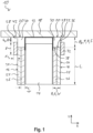
- FIG. 1 a drywall 10 with a drywall profile 12, a stand construction 14 and planking 16 is shown in cross section on each end face.
- the drywall profile 12 is a ceiling profile with a U-shaped cross section, which is firmly anchored to a component 18 extending in the horizontal direction X, for example by means of dowels and screws.
- each end face is fastened to the stand structure 14 at a distance from the component 18, for example by means of screws, thereby creating an expansion joint 20 in the form of a ceiling joint in the vertical direction Y between a peripheral side 22 of the corresponding paneling 16 and the component 18 is formed.
- the stand structure 14 is movably attached to the drywall profile 12 in the vertical direction Y over a distance S, which corresponds in its length and orientation to an intended maximum movement absorption F.
- the drywall profile 12 can have corresponding elongated holes which extend in the vertical direction Y and in which the stand structure 14 is slidably mounted via fasteners, such as screws.
- each end face of the drywall 10 is formed in the present embodiment by a first planking part 26 and a second planking part 24, which rest against one another in the horizontal direction X across their end faces.
- each paneling 16 is a two-layer paneling.
- planking parts 24, 26 are drywall panels, such as plasterboard or gypsum fiber panels.
- the paneling parts 24, 26 each have a wall thickness w in the horizontal direction X and a height L in the vertical direction Y.
- Each paneling 16 thus has a total wall thickness W in the horizontal direction X, which corresponds to twice the wall thickness w.
- the movement joints 20 therefore each have a width G in the horizontal direction X, which corresponds to the total wall thickness W of the paneling 16.
- the paneling parts 24, 26 of each paneling 16 end at the same height in the vertical direction Y and thus form a substantially flat peripheral side 22 of the corresponding paneling 16.
- the first paneling part 26 and the second paneling part 24 are not arranged vertically offset from one another.
- the drywall 10 can have paneling 16 only on one end face.
- each paneling 16 can have any number of layers or paneling parts 24, 26.
- paneling parts 24, 26 can each consist of any material and/or have any dimensions.
- the drywall 10 has a sealing device 28 for each movement joint 20.
- component 18 is a ceiling.
- the component 18 can be any component, for example a crossbar.
- sealing device 28 is also suitable for sealing an expansion joint 20 between the drywall 10 and a wall and/or a floor, which in particular extend perpendicular to the drywall 10 analogously to the component 18.
- sealing devices 28 are designed identically here, the structure of the sealing devices 28 will be described below using a sealing device 28 as an example.
- the sealing device 28 comprises a sealing profile 30, which is arranged in the movement joint 20, and a protective plate 32, which is on the outer end face 34 of the paneling 16 with an offset V (see Figure 3 ) is attached opposite the peripheral side 22.
- the protective plate 32 is a plasterboard panel with a height I in the vertical direction Y, and is shaped in such a way that it can be securely fastened in the stand structure 14.
- the protective plate 32 has a minimum height of approximately 100 mm. This allows a screw, such as a drywall screw, to be securely fastened in the stand structure 14.
- An ordinary drywall profile 12 typically has a height of around 50 mm; However, the protective plate 32 should always have a greater height I than the drywall profile height. The screw in the protective plate 32 must be positioned so that even with a compressed joint, the screw does not abut the drywall profile 12.
- the protective plate 32 is a plasterboard with a height I in the vertical direction Y, and a wall thickness d in the horizontal direction
- the protective plate 32 can consist of any desired, preferably inorganic, material, for example metal; Plaster or cement are also conceivable.
- the protective plate 32 can have a height I that corresponds to less than 50% of the length L of the paneling 16, in particular less than 20%.
- the protective plate 32 can have a wall thickness d that corresponds to less than 25% of the total wall thickness W of the paneling 16.
- the sealing profile 30 consists of a foam, which can optionally include an intumescent material.
- a functional element made of intumescent material can be attached to the sealing profile 30.
- the sealing profile 30 has a rectangular cross section with a width B in the horizontal direction
- the sealing profile 30 can have a width B that is between 100% and 110% of the total wall thickness W of the paneling 16, and/or a height H that is between 100% and 110% of the intended maximum movement absorption F.
- the sealing profile 30 has a lateral contact surface 36, on which the protective plate 32 rests on the front side, as well as a contact surface 38, which lies opposite the peripheral side 22 and on which the paneling 16 rests over the peripheral side 22 in certain positions of the component 18, as described below is.
- the sealing profile 30 can have any cross-section, as long as it is guaranteed that the sealing profile 30 reliably seals the expansion joint 20 in all positions of the drywall 10 or the component 18 for which the sealing device 28 is intended.
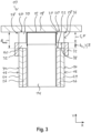
- the drywall 10 is designed in such a way that the expansion of the movement joint 20 adapts in the vertical direction Y when the component 18 is in a neutral position (see Figure 1 ) lowers in the vertical direction Y (see Figure 2 ) or lifts (see Figure 3 ), for example due to weight loads and/or thermal expansion.
- the direction of expansion of the movement joint 20 corresponds here to the vertical direction Y.
- the Figure 2 shows the drywall 10 with the component 18 in a position deflected maximally downwards in the vertical direction Y, while the Figure 3 the component 18 shows in a position deflected maximally upwards in the vertical direction Y.
- maximum refers to the positions for which the drywall 10 or the sealing device 28 is designed.
- the movement joint 20 In the neutral position (see Figure 1 ), the movement joint 20 has an extent A N and the paneling 16 lies with the peripheral side 22 on the contact surface 38.
- the protective plate 32 is arranged in the neutral position at a distance D in the vertical direction Y from the component 18.
- the expansion joint 20 In the maximum downwardly deflected position (see Figure 2 ), the expansion joint 20 has an extent A min , with the sealing profile 30 being compressed in the vertical direction Y.
- the sealing profile 30 is attached to the component 18 and/or the drywall profile 12 in a way that does not significantly hinder compression.
- the movement joint 20 In the maximum upwardly deflected position (see Figure 3 ), the movement joint 20 has an extent A max and the planking 16 is no longer in contact with the sealing profile 30, but the peripheral side 22 and the contact surface 38 are separated from each other by a gap 40, which has a height Z in the vertical direction Y.
- the intended maximum movement absorption F is composed of the maximum possible movement b1 in the vertical direction Y and the maximum possible movement b2 against the vertical direction Y, which the planking 16 can carry out relative to the neutral position.
- the distance D, the height Z and the offset V are the same size and each correspond to half of the intended maximum movement absorption F.
- planking 16 and the sealing devices 28 of the two end faces of the drywall 10 are designed analogously to one another, reference will only be made below to one planking 16 and the corresponding sealing device 28.
- the drywall profile 12 is attached to the component 18 in a first step.
- the sealing profile 30 is attached to the component 18 and/or the drywall profile 12 in the movement joint 20, or at the point where the movement joint 20 is formed in the following steps, for example in a materially bonded manner.
- planking 16 is movably fastened to the drywall profile 12 in the vertical direction Y using the screws.
- peripheral side 22 of the paneling 16 is brought into contact with the contact surface 38 of the sealing profile 30, so that the paneling 16 is arranged at a distance A N from the component 18.
- the sealing profile 30 has a height H that is greater than the distance A N , the sealing profile 30 is correspondingly compressed in the vertical direction Y.
- the distance A N corresponds to the maximum intended movement absorption F.
- the protective plate 32 is fastened to the end face 34 of the planking 16 at a distance D from the component 18 and at an offset V from the paneling 16.
- the protective plate 32 comes into contact at the front with the side contact surface 36 of the sealing profile 30, which is accordingly compressed in the horizontal direction case is.
- the sealing profile 30 is essentially only arranged in the movement joint 20 and does not protrude beyond it, in particular not into the gap 42 between the protective plate 32 and the component 18.
- the distance D corresponds to half of the maximum intended movement absorption F.
- the sealing profile 30 is only inserted into the expansion joint 20 after the paneling 16 has been attached.
- the sealing profile 30 is attached to the component 18 in front of the drywall profile 12 or together with it.
- a drywall 10 and a method for producing a drywall 10 are provided, which has a particularly effective and compact sealing device 28 for sealing the expansion joint 20.
- the sealing device 28 is designed in such a way that the sealing profile 30 is compressed by a maximum of 50% in the vertical direction Y. This ensures that the sealing profile 30 made of foam is only deformed elastically and is therefore not damaged.
- the offset Z corresponds to half of the maximum intended movement absorption F and the sealing profile 30 has a height H which corresponds at least to the maximum intended movement absorption F ensures that the movement joint 20 is reliably protected by the sealing device 28 in all positions of the component 18 is sealed.
- the drywall 10 can be manufactured or assembled using the method with little effort.
Landscapes
- Engineering & Computer Science (AREA)
- Architecture (AREA)
- Physics & Mathematics (AREA)
- Electromagnetism (AREA)
- Civil Engineering (AREA)
- Structural Engineering (AREA)
- Building Environments (AREA)
Priority Applications (1)
| Application Number | Priority Date | Filing Date | Title |
|---|---|---|---|
| EP22178798.9A EP4293168A1 (fr) | 2022-06-14 | 2022-06-14 | Cloison sèche, ainsi que procédé de fabrication d'une cloison sèche |
Applications Claiming Priority (1)
| Application Number | Priority Date | Filing Date | Title |
|---|---|---|---|
| EP22178798.9A EP4293168A1 (fr) | 2022-06-14 | 2022-06-14 | Cloison sèche, ainsi que procédé de fabrication d'une cloison sèche |
Publications (1)
| Publication Number | Publication Date |
|---|---|
| EP4293168A1 true EP4293168A1 (fr) | 2023-12-20 |
Family
ID=82058125
Family Applications (1)
| Application Number | Title | Priority Date | Filing Date |
|---|---|---|---|
| EP22178798.9A Pending EP4293168A1 (fr) | 2022-06-14 | 2022-06-14 | Cloison sèche, ainsi que procédé de fabrication d'une cloison sèche |
Country Status (1)
| Country | Link |
|---|---|
| EP (1) | EP4293168A1 (fr) |
Citations (3)
| Publication number | Priority date | Publication date | Assignee | Title |
|---|---|---|---|---|
| EP3056625A1 (fr) * | 2015-02-13 | 2016-08-17 | HILTI Aktiengesellschaft | Bande d'étanchéité pour joint et système d'étanchéité doté d'une telle bande d'étanchéité |
| US20170260741A1 (en) * | 2016-03-11 | 2017-09-14 | Rectorseal, Llc | Systems and methods for assisting in reducing the spread of fire, smoke or heat in a building |
| EP3553241A1 (fr) * | 2018-04-12 | 2019-10-16 | HILTI Aktiengesellschaft | Joint d'étanchéité et dispositif d'étanchéité destiné à l'étanchéité d'un joint |
-
2022
- 2022-06-14 EP EP22178798.9A patent/EP4293168A1/fr active Pending
Patent Citations (3)
| Publication number | Priority date | Publication date | Assignee | Title |
|---|---|---|---|---|
| EP3056625A1 (fr) * | 2015-02-13 | 2016-08-17 | HILTI Aktiengesellschaft | Bande d'étanchéité pour joint et système d'étanchéité doté d'une telle bande d'étanchéité |
| US20170260741A1 (en) * | 2016-03-11 | 2017-09-14 | Rectorseal, Llc | Systems and methods for assisting in reducing the spread of fire, smoke or heat in a building |
| EP3553241A1 (fr) * | 2018-04-12 | 2019-10-16 | HILTI Aktiengesellschaft | Joint d'étanchéité et dispositif d'étanchéité destiné à l'étanchéité d'un joint |
Similar Documents
| Publication | Publication Date | Title |
|---|---|---|
| EP0581269B1 (fr) | Système d'isolation thermique extérieure et de traitement de surface | |
| EP3256663B1 (fr) | Bande d'étanchéité de joint ayant une géométrie prédéfinie et système d'étanchéité doté d'une telle bande d'étanchéité de joint | |
| EP4200493B1 (fr) | Dispositif d'étanchéité pour joint de bord double ainsi que cloison pour pose à sec | |
| EP4200487B1 (fr) | Dispositif d'étanchéité pour le joint de bord d'une cloison pour pose à sec, cloison pour pose à sec ainsi que procédé de fabrication d'une cloison pour pose à sec | |
| AT511220A1 (de) | Deckenelement zur ausbildung von gebäudedecken | |
| EP3060725B1 (fr) | Composite anti-effraction et structure de mur porteur, de toit ou de plafond | |
| DE3128165C2 (de) | Schalldämmendes Wandbausystem für Industriebauten, sowie Kassettenprofil hierfür | |
| EP1525358B1 (fr) | Couche isolante en fibres minerales et paroi de batiment | |
| EP4293168A1 (fr) | Cloison sèche, ainsi que procédé de fabrication d'une cloison sèche | |
| EP0947638A2 (fr) | Panneau d'isolation pour façades extérieures de maisons | |
| DE102021107507B3 (de) | Einsatzmodul für ein Wandelement und Wandelement mit Einsatzmodul | |
| EP3553241A1 (fr) | Joint d'étanchéité et dispositif d'étanchéité destiné à l'étanchéité d'un joint | |
| DE9320234U1 (de) | Abdichtung gegen das Eindringen gefährlicher Gase, insbesondere Radon, aus dem Baugrund | |
| AT413410B (de) | Holzwandtafel | |
| EP0106297A2 (fr) | Elément de construction pour la fabrication de murs en béton et mur de bâtiment fabriqué avec celui-ci | |
| DE202021101571U1 (de) | Einsatzmodul für ein Wandelement und Wandelement mit Einsatzmodul | |
| DE7720341U1 (de) | Als baukonstruktionselement verwendbare platte | |
| EP3015614A1 (fr) | Plaque murale pour cloison seche en materiau derive du bois et montage de mur et procede de fabrication | |
| DE102020131498A1 (de) | Zargenteil, Zarge sowie Fenstereinbauelement mit Kompressionseinlage | |
| EP1527237B1 (fr) | Element isolant et mur de construction | |
| DE19916247A1 (de) | Baukastensystem für Fertighäuser | |
| DE102022131325B4 (de) | Anordnung von Schalungselementen | |
| EP3085873B1 (fr) | Panneau a effet | |
| EP3024992B1 (fr) | Système de fixation d'éléments isolants | |
| DE102019003036B4 (de) | Wärmedämmbaugruppe |
Legal Events
| Date | Code | Title | Description |
|---|---|---|---|
| PUAI | Public reference made under article 153(3) epc to a published international application that has entered the european phase |
Free format text: ORIGINAL CODE: 0009012 |
|
| STAA | Information on the status of an ep patent application or granted ep patent |
Free format text: STATUS: THE APPLICATION HAS BEEN PUBLISHED |
|
| AK | Designated contracting states |
Kind code of ref document: A1 Designated state(s): AL AT BE BG CH CY CZ DE DK EE ES FI FR GB GR HR HU IE IS IT LI LT LU LV MC MK MT NL NO PL PT RO RS SE SI SK SM TR |
|
| STAA | Information on the status of an ep patent application or granted ep patent |
Free format text: STATUS: REQUEST FOR EXAMINATION WAS MADE |
|
| 17P | Request for examination filed |
Effective date: 20240620 |
|
| RBV | Designated contracting states (corrected) |
Designated state(s): AL AT BE BG CH CY CZ DE DK EE ES FI FR GB GR HR HU IE IS IT LI LT LU LV MC MK MT NL NO PL PT RO RS SE SI SK SM TR |
|
| GRAP | Despatch of communication of intention to grant a patent |
Free format text: ORIGINAL CODE: EPIDOSNIGR1 |
|
| STAA | Information on the status of an ep patent application or granted ep patent |
Free format text: STATUS: GRANT OF PATENT IS INTENDED |