EP4293202A1 - Soupape de purge avec séparation air-huile - Google Patents
Soupape de purge avec séparation air-huile Download PDFInfo
- Publication number
- EP4293202A1 EP4293202A1 EP23178941.3A EP23178941A EP4293202A1 EP 4293202 A1 EP4293202 A1 EP 4293202A1 EP 23178941 A EP23178941 A EP 23178941A EP 4293202 A1 EP4293202 A1 EP 4293202A1
- Authority
- EP
- European Patent Office
- Prior art keywords
- valve
- valve member
- outlet
- mixture
- chamber
- Prior art date
- Legal status (The legal status is an assumption and is not a legal conclusion. Google has not performed a legal analysis and makes no representation as to the accuracy of the status listed.)
- Pending
Links
Images




Classifications
-
- F—MECHANICAL ENGINEERING; LIGHTING; HEATING; WEAPONS; BLASTING
- F16—ENGINEERING ELEMENTS AND UNITS; GENERAL MEASURES FOR PRODUCING AND MAINTAINING EFFECTIVE FUNCTIONING OF MACHINES OR INSTALLATIONS; THERMAL INSULATION IN GENERAL
- F16N—LUBRICATING
- F16N23/00—Special adaptations of check valves
-
- F—MECHANICAL ENGINEERING; LIGHTING; HEATING; WEAPONS; BLASTING
- F01—MACHINES OR ENGINES IN GENERAL; ENGINE PLANTS IN GENERAL; STEAM ENGINES
- F01D—NON-POSITIVE DISPLACEMENT MACHINES OR ENGINES, e.g. STEAM TURBINES
- F01D17/00—Regulating or controlling by varying flow
- F01D17/10—Final actuators
- F01D17/12—Final actuators arranged in stator parts
- F01D17/14—Final actuators arranged in stator parts varying effective cross-sectional area of nozzles or guide conduits
- F01D17/141—Final actuators arranged in stator parts varying effective cross-sectional area of nozzles or guide conduits by means of shiftable members or valves obturating part of the flow path
-
- B—PERFORMING OPERATIONS; TRANSPORTING
- B01—PHYSICAL OR CHEMICAL PROCESSES OR APPARATUS IN GENERAL
- B01D—SEPARATION
- B01D19/00—Degasification of liquids
-
- F—MECHANICAL ENGINEERING; LIGHTING; HEATING; WEAPONS; BLASTING
- F01—MACHINES OR ENGINES IN GENERAL; ENGINE PLANTS IN GENERAL; STEAM ENGINES
- F01D—NON-POSITIVE DISPLACEMENT MACHINES OR ENGINES, e.g. STEAM TURBINES
- F01D25/00—Component parts, details, or accessories, not provided for in, or of interest apart from, other groups
- F01D25/18—Lubricating arrangements
-
- F—MECHANICAL ENGINEERING; LIGHTING; HEATING; WEAPONS; BLASTING
- F01—MACHINES OR ENGINES IN GENERAL; ENGINE PLANTS IN GENERAL; STEAM ENGINES
- F01D—NON-POSITIVE DISPLACEMENT MACHINES OR ENGINES, e.g. STEAM TURBINES
- F01D25/00—Component parts, details, or accessories, not provided for in, or of interest apart from, other groups
- F01D25/18—Lubricating arrangements
- F01D25/20—Lubricating arrangements using lubrication pumps
-
- F—MECHANICAL ENGINEERING; LIGHTING; HEATING; WEAPONS; BLASTING
- F05—INDEXING SCHEMES RELATING TO ENGINES OR PUMPS IN VARIOUS SUBCLASSES OF CLASSES F01-F04
- F05D—INDEXING SCHEME FOR ASPECTS RELATING TO NON-POSITIVE-DISPLACEMENT MACHINES OR ENGINES, GAS-TURBINES OR JET-PROPULSION PLANTS
- F05D2260/00—Function
- F05D2260/60—Fluid transfer
- F05D2260/602—Drainage
-
- F—MECHANICAL ENGINEERING; LIGHTING; HEATING; WEAPONS; BLASTING
- F05—INDEXING SCHEMES RELATING TO ENGINES OR PUMPS IN VARIOUS SUBCLASSES OF CLASSES F01-F04
- F05D—INDEXING SCHEME FOR ASPECTS RELATING TO NON-POSITIVE-DISPLACEMENT MACHINES OR ENGINES, GAS-TURBINES OR JET-PROPULSION PLANTS
- F05D2260/00—Function
- F05D2260/60—Fluid transfer
- F05D2260/609—Deoiling or demisting
-
- F—MECHANICAL ENGINEERING; LIGHTING; HEATING; WEAPONS; BLASTING
- F05—INDEXING SCHEMES RELATING TO ENGINES OR PUMPS IN VARIOUS SUBCLASSES OF CLASSES F01-F04
- F05D—INDEXING SCHEME FOR ASPECTS RELATING TO NON-POSITIVE-DISPLACEMENT MACHINES OR ENGINES, GAS-TURBINES OR JET-PROPULSION PLANTS
- F05D2260/00—Function
- F05D2260/98—Lubrication
-
- F—MECHANICAL ENGINEERING; LIGHTING; HEATING; WEAPONS; BLASTING
- F16—ENGINEERING ELEMENTS AND UNITS; GENERAL MEASURES FOR PRODUCING AND MAINTAINING EFFECTIVE FUNCTIONING OF MACHINES OR INSTALLATIONS; THERMAL INSULATION IN GENERAL
- F16N—LUBRICATING
- F16N2210/00—Applications
- F16N2210/08—Aircraft
Definitions
- Aircraft (e.g., gas turbine) engines have rotors that are rotatably supported by bearings.
- the bearings are supplied with oil which may be scavenged from the bearing chambers (sometimes called "bearing cavities"), and processed (e.g., cooled, filtered, deaerated) for recycling.
- the bearing chambers sometimes called "bearing cavities”
- processed e.g., cooled, filtered, deaerated
- RPM revolutions per minute
- the disclosure describes a blowdown valve for an aircraft engine lubrication system.
- the blowdown valve comprises: a valve body defining:
- the disclosure describes an aircraft engine lubrication system comprising:
- the disclosure describes a method for separating oil and air in a lubrication system of an aircraft engine.
- the method comprises:
- blowdown valves and associated methods.
- the blowdown valves and methods described herein may promote air-oil separation and facilitate scavenging of the oil for recycling.
- connection and coupling may include both direct connection and coupling (in which two elements contact each other) and indirect connection and coupling (in which at least one additional element is located between the two elements).
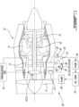
- FIG. 1 illustrates an aircraft engine 10 (referred hereinafter as "engine 10") depicted as a turbofan gas turbine engine of a type preferably provided for use in subsonic flight, generally comprising, in serial flow communication, fan 12 through which ambient air is propelled, compressor section 14 for pressurizing the air, combustor 16 in which the compressed air is mixed with fuel and ignited for generating an annular stream of hot combustion gases, and turbine section 18 for extracting energy from the combustion gases.
- engine 10 depicted as a turbofan gas turbine engine of a type preferably provided for use in subsonic flight, generally comprising, in serial flow communication, fan 12 through which ambient air is propelled, compressor section 14 for pressurizing the air, combustor 16 in which the compressed air is mixed with fuel and ignited for generating an annular stream of hot combustion gases, and turbine section 18 for extracting energy from the combustion gases.
- engine 10 depicted as a turbofan gas turbine engine of a type preferably provided for use in subsonic flight, generally comprising, in serial flow
- blowdown valves may be used on other types of aircraft engines such as internal combustion (e.g., piston, rotary) engines, and various types of (e.g., turbofan, turboshaft, turboprop) gas turbine engines that may be used to propel an aircraft, or that may be used as auxiliary power unit(s) onboard an aircraft.
- internal combustion e.g., piston, rotary
- turbofan, turboshaft, turboprop gas turbine engines that may be used to propel an aircraft, or that may be used as auxiliary power unit(s) onboard an aircraft.
- Engine 10 may include one or more lubrication loads (e.g., rotors, shafts, bearings, gears).
- shaft 20 may be rotatably supported within engine 10 by (e.g., roller, journal) bearing 22 and by one or more other bearings (not shown).
- Shaft 20 may be a low-pressure shaft of engine 10 but bearing 22 may instead support a highpressure shaft or another shaft of engine 10.
- Bearing 22 may be disposed inside bearing chamber 23 and may be operatively disposed between shaft 20 and suitable support structure (e.g., casing) of engine 10.
- Engine 10 may include another chamber such as gearbox 24 including gears 25 arranged to define one or more (e.g., speed reducing or speed augmenting) gear trains.
- gearbox 24 may be an accessory gearbox (AGB) that may receive motive power from shaft 20 or from another shaft of engine 10 (e.g., via tower shaft 26) and drive one or more accessories such as an electric generator and/or oil pumps 28, 34 for example.
- Gearbox 24 may have an input drivingly coupled to tower shaft 26 and one or more outputs respectively drivingly coupled to the one or more accessories via accessory mounting pads.
- Engine 10 may include lubrication system 30 (referenced hereinafter as "system 30") for supplying oil from oil tank 32 to bearing 22 of bearing chamber 23, to gears 25 of gearbox 24, and/or to one or more other lubrication loads.
- System 30 may include one or more oil pressure pumps 28 for driving oil from oil tank 32 to bearing 22, to gearbox 24, and optionally to other lubrication loads.
- Air-oil mixture 31 from bearing chamber 23 may be vented from bearing chamber 23 and then supplied to one or more downstream chambers (e.g., gearbox 24) containing other lubrication loads before being scavenged from the downstream chamber and returned to oil tank 32.
- System 30 may include one or more oil scavenge pumps 34 for evacuating the oil from gearbox 24 and optionally from other lubrication loads, and returning the oil to oil tank 32 for eventual reuse (i.e., recycling).
- System 30 may include other components for processing (e.g., cooling, filtering, deaerating) the oil in preparation for recycling the oil.
- Pressure pump 28 may deliver oil from oil tank 32 to bearing 22 for lubrication and cooling purposes.
- One or more seals of bearing chamber 23 in which bearing 22 is disposed may also receive pressurized air 33 to prevent the oil from leaking out of bearing chamber 23.
- pressurized air 33 may be supplied from compressor section 14 via a suitable bleed port. Some of pressurized air 33 may flow into bearing chamber 23 and mix with the oil inside of bearing chamber 23. The rotating shaft supported by bearing 22 may cause misting of the oil inside of bearing chamber 23.
- air-oil mixture 31 may be generated inside of bearing chamber 23, vented from bearing chamber 23 and directed toward gearbox 24 or other downstream chamber(s) disposed in series with bearing chamber 23 in system 30.
- System 30 may include blowdown valve 35 (also referred hereinafter as "valve 35").
- Air-oil mixture 31 vented from bearing chamber 23 may be directed to a downstream chamber such as gearbox 24 via valve 35.
- Valve 35 may a blowdown type of valve serving to control a (e.g., continuous) flow of air-oil mixture 31 being vented from bearing chamber 23 and injected into to gearbox 24 due to a differential pressure between bearing chamber 23 and gearbox 24.
- the pressure inside of bearing chamber 23 may be greater than the pressure inside of gearbox 24 thereby causing air-oil mixture 31 to flow from bearing chamber 23 to gearbox 24.
- Valve 35 may have inlet 36 for receiving air-oil mixture 31 from bearing chamber 23, one or more first outlets 38 for releasing a first portion of air-oil mixture 31 into gearbox 24, and one or more second outlets 40 for releasing a second portion of air-oil mixture 31 into gearbox 24.
- valve 35 may promote air-oil separation of the received air-oil mixture 31 upon entry into gearbox 24.
- the second portion of air-oil mixture 31 released from valve 35 may have a greater (e.g., volume, mass) fraction of oil than the first portion of air-oil mixture 31 released from valve 35.
- the air from air-oil mixture 31 may be primarily released from valve 35 via first outlet 38, and the oil from air-oil mixture 31 may be primarily released from valve 35 via second outlet 40.
- Valve 35 may be installed on an internal wall of gearbox 24 so that first outlet 38 and second outlet 40 may be respectively directed toward suitable locations within gearbox 24.
- valve 35 may be at least partially disposed inside of gearbox 24.
- first outlet 38 and second outlet 40 may be at different orientations and/or locations to reduce or discourage misting of the oil within gearbox 24.
- first outlet 38 may be oriented to promote the flow of air discharged from first outlet 38 toward breather port 42 via which some of the air inside of gearbox 24 may be vented overboard.
- second outlet 40 may be oriented toward a relatively quiet location (e.g., toward a proximate wall, toward a lower location) within gearbox 24 to discourage entrainment of the oil with the turbulence inside of gearbox 24 and thereby discourage misting.
- second outlet 40 may be oriented to discourage the flow of oil toward breather port 42 to reduce the potential for breather port 42 getting contaminated (choked) with oil.
- the locations and/or orientations of first outlet 38 and second outlet 40 may be selected based on expected fluid flow patterns induced within gearbox 24.
- valve 35 may be used to control the flow of air-oil mixture 31 between two suitable lubrication loads disposed in series along a lubrication circuit and having a pressure differential therebetween.
- oil is referenced herein as a lubricating fluid, it is understood that blowdown valves and methods described herein may be suitable for use with other fluids such as fuel or other liquid cooling fluids for example.
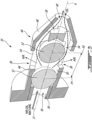
- FIG. 2 is a perspective view of an exemplary blowdown valve 35, which may be part of system 30.
- Valve 35 may include valve body 44.
- Valve body 44 may have a unitary construction (i.e., single piece), or may include a plurality of components assembled together.
- Valve body 44 may be made from a suitable metallic material such as steel.
- Valve body 44 may include cage 46 and nozzle 48, which may be integrally formed, or that may be assembled together by threaded engagement or by welding.
- cage 46 may include four first outlets 38 (e.g., equally) spaced apart about central axis A.
- central axis A may intersect inlet 36, valve member 52 and second outlet 40.
- Second outlet(s) 38 may include openings that are oriented transversely (e.g., perpendicular) to central axis A.
- FIG. 3 is a perspective cross-sectional view of valve 35 of FIG. 2 taken along line 3-3 in FIG. 2 .
- FIG. 3 shows a first instance of valve member 52 in valve-closed position P1 in broken lines, and a second instance of valve member 52 in valve-open position P2 in solid lines.
- the two instances of valve member 52 are intended to illustrate the range of movement (e.g., translation) of valve member 52 inside of valve chamber 50 and along central axis A of cage 46.
- Cage 46 may serve as a guide for the movement of valve member 52 inside of valve chamber 50.
- Valve body 44 may include keeper 56, which may be inserted into cage 46 and attached to cage 46 to prevent valve member 52 from escaping valve chamber 50. The absence of keeper 56 may permit the insertion of valve member 52 into valve chamber 50.
- Keeper 56 may be an annular member made from a metallic material and that is assembled cage 46 by threaded engagement for example. Keeper 56 may also define a valve seat for interacting with valve member 52 when valve member 52 is at valve-closed position P1 where valve member 52 hinders (e.g., prevents) fluid flow through inlet 36. Keeper 56 may define an upstream translation limit for valve member 52.
- Cage 46 may include end cap 58 at a distal (e.g., downstream) end thereof. End cap 58 may interact with valve member 52 when valve member 52 is at valve-open position P2. End cap 58 may define a downstream translation limit for valve member 52. The fenestration of cage 46 may extend through end cap 58 permit the flow of air-oil mixture 31 around valve member 52 and out of outlet 40 when valve member 52 is at valve-open position P2.
- an upstream surface of valve member 52 facing inlet 36 and facing the incoming flow of air-oil mixture 31 may have a bulbous shape.
- the upstream surface of valve member 52 may have a spherical shape so that valve member 52 may define part of a sphere.
- valve member 52 may be a metallic ball (e.g., sphere) that is translatable inside of valve chamber 50 and along central axis A.
- valve member 52 may be translated toward valve-open position P2 so that air-oil mixture 31 may enter valve chamber 50 via inlet 36.
- first fluid passages may be defined from inlet 36 to first outlet(s) 38.
- second fluid passages may be defined from inlet 36 to second outlet 40.
- the second fluid passage(s) may extend around and past valve member 52, through the fenestration of cage 46, into nozzle 48 and to second outlet 40.
- Valve member 52 may be disposed between inlet 36 and second outlet 40.
- Second outlet 40 may be disposed downstream of first outlet(s) 38.
- valve member 52 is at valve-open position P2
- at least part of first outlet 38 may be disposed upstream of valve member 52.
- Air-oil mixture 31 entering valve chamber 50 may impinge against valve member 52.
- the presence of valve member 52 and the configuration of valve body 44 may promote separation of the air and the oil in air-oil mixture 31 received into valve chamber 50. It is understood that the air-oil separation may not be absolute. For example, some or most of the air (i.e., the portion of air-oil mixture 31 having a lower density) may tend to exit valve chamber 50 radially and out of first outlet(s) 38. On the other hand, some or most of the oil (i.e., the portion of air-oil mixture 31 having a higher density) may tend to flow around valve member 52 and exit valve chamber 50 via the fenestration in cage 46, and exit valve 35 via second outlet 40 defined by converging nozzle 48.
- air-oil mixture 31 may contain more air than oil in terms of volume fraction. In some situations, air-oil mixture 31 may have an oil volume fraction of 15% or less. In some situations, air-oil mixture 31 may have an oil volume fraction of between 5% and 15%. In some situations, air-oil mixture 31 may contain more oil than air in terms of volume fraction.
- valve member 52 may be freely movable so that in the event of a reversal of the pressure differential, valve member 52 would then be urged toward valve-closed position P1 and interact with the valve seat defined by keeper 56 to hinder (e.g., prevent) fluid flow in the reverse direction (e.g., from gearbox 24 toward bearing chamber 23).
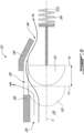
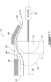
- the position of upstream end 48A of nozzle 48 along central axis A may be characterized by angle a measured relative to the center 52A of the spherical valve member 52, relative to an axial position that is axially aligned with center 52A along central axis A, and in a plane that contains central axis A.
- upstream end 48A of nozzle 48 may be disposed upstream of center 52A so that angle ⁇ may be between 0 and 20°.
- upstream end 48A of nozzle 48 may be axially aligned with center 52A so that angle ⁇ may be about 0°.
- upstream end 48A of nozzle 48 may be disposed downstream of center 52A so that angle ⁇ may be between 0 and -15° (i.e., in the opposite direction to that shown in FIG. 4 ). In various embodiments, angle ⁇ may be between 20 and -15° for example.
- Upstream end 48A of nozzle 48 may define a capture zone for catching oil that has impinged against valve member 52 and is being deflected radially outwardly by valve member 52.
- nozzle 48 may capture the oil deposited on valve member 52 and in a flow stagnation region caused by the relatively high turning acceleration. The layer of oil may tend to move over and around valve member 52 due to the local pressure distribution encouraged by nozzle 48. Nozzle 48 may then guide the oil and some quantity of air toward second outlet 40.
- the fenestration in cage 46 and radial gap G between nozzle 48 and valve member 52 may define part of a flow passage establishing fluid communication between inlet and second outlet 40.
- the flow passage may extend around and past valve member 52.
- valve member 52 may provide an obstruction to the general flow direction along central axis A and the flow passage may extend around valve member 52 to bypass the obstruction.
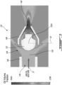
- FIG. 5 is a plot showing results of a computational fluid dynamics (CFD) simulation of a flow of an exemplary air-oil mixture 31 through another exemplary blowdown valve 135 (referred hereinafter as "valve 135").
- Valve 135 may have elements previously described above in relation to valve 35. Like elements have been identified using reference characters incremented by 100.
- valve member 152 may be fully spherical, partially spherical or non-spherical.
- the upstream surface of valve member 152 facing toward inlet 136 may be bulbous (e.g. convex toward inlet 136).
- valve member 152 may be partially spherical so that the upstream surface of valve member 152 may be spherical and may have center 152A.
- the plot in FIG. 5 shows dark regions of relatively high oil volume fraction and light regions of relatively low oil volume fraction.
- Air-oil mixture 31 may be received into chamber 150 defined by cage 146, and impinged against the upstream surface of valve member 152.
- the plot of FIG. 5 shows that the second portion of air-oil mixture 31 that is collected by nozzle 148, guided by nozzle 148 and released from second outlet 140 has a higher volume fraction of oil than the first portion of air-oil mixture 31 that is released from first inlets 138.
- FIG. 6 is a partial schematic axial cross-sectional view of another exemplary blowdown valve 235 (referred hereinafter as "valve 235").
- valve 235 may have elements previously described above in relation to valve 35. Like elements have been identified using reference characters incremented by 200.
- FIG. 6 shows a first instance of valve member 252 at valve-closed position P1 shown in broken lines, and a second instance of valve member 252 at valve-open position P2 shown in solid lines.
- valve member 252 may be resiliently biased toward valve-closed position P1 by way of spring 260 so that a minimum pressure differential may be required to cause valve member 252 to move toward valve-open position P2.
- air-oil mixture 31 may be received into chamber 250 via inlet 236, and impinged against the upstream surface of valve member 252.
- the first portion of air-oil mixture 31 may be released from first inlet(s) 238, and the second portion of air-oil mixture 31 may be collected by nozzle 248, guided by nozzle 248 and released from second outlet 240.
- FIG. 7 is a partial schematic axial cross-sectional view of another exemplary blowdown valve 335 (referred hereinafter as "valve 335").
- valve 335" a partial schematic axial cross-sectional view of another exemplary blowdown valve 335
- FIG. 7 only shows a portion of cage 346 and of nozzle 348 above central axis A.
- Valve 335 may have elements previously described above in relation to valve 35. Like elements have been identified using reference characters incremented by 300.
- FIG. 7 shows a first instance of valve member 352 at valve-closed position P1 shown in broken lines, and a second instance of valve member 352 at valve-open position P2 shown in solid lines.
- valve member 352 may be movable (translatable) between valve-closed position P1 and valve-open position P2 by way of actuator 362.
- Actuator 362 may be a hydraulic or electric actuator and configured to cause translation of valve member 352 as a function of an operating parameter of engine 10 for example.
- air-oil mixture 31 may be received into chamber 350 via inlet 336, and impinged against the upstream surface of valve member 352.
- the first portion of air-oil mixture 31 may be released from first inlet(s) 338, and the second portion of air-oil mixture 31 may be collected by nozzle 348, guided by nozzle 348 and released from second outlet 340.
- FIGS. 8A and 8B are schematic axial cross-sectional views of another exemplary blowdown valve 435 (referred hereinafter as "valve 435").
- Valve 435 may have elements similar to those previously described above in relation to valve 35. Like elements have been identified using reference characters incremented by 400.
- FIG. 8A shows valve member 452 at valve-closed position P1.
- FIG. 8B shows valve member 452 at valve-open position P2.
- valve member 352 may be freely movable (translatable) between valve-closed position P1 and valve-open position P2, may be resiliently biased toward valve-closed position P1 by way of a spring, or may be movable by way of a suitable actuator.
- valve member 452 may have the form of a poppet including a disc attached to an end of a stem. Valve member 452 may be disposed inside cage 446. With valve member 452 in valve-open position P2, air-oil mixture 31 may be received into chamber 450 via inlet 436, and impinged against the upstream surface of valve member 452. The first portion of air-oil mixture 31 may be released from first inlet(s) 438, and the second portion of air-oil mixture 31 may be directed toward nozzle 448 using one or more deflectors 464, collected by nozzle 448, guided by nozzle 448 and released from second outlet 440. In some embodiments, deflector(s) 464 may form part of and movable with valve member 452. Alternatively, deflector(s) 464 may be separate from valve member 452 and have a fixed position associated with valve-open position of valve member 452.
- FIG. 9 is a flow diagram of method 1000 of separating oil and air in a lubrication system of engine 10.
- Method 1000 may be performed using any one of valves 35, 135, 235, 335 and 435 described herein or using other component(s). Aspects of valve 35, 135, 235, 335 and 435 and/or of system 30 may be incorporated into method 1000. Method 1000 may include other steps or actions disclosed herein. Only reference numerals associated with valve 35 are used in the following description for clarity. In various embodiments, method 1000 may include:
- Valve member 52 may be translatable along central axis A of cage 46.
- the first portion of air-oil mixture 31 may be release from blowdown valve 35 in a direction transverse to central axis A.
- the second portion of air-oil mixture 31 may be released from blowdown valve 35 via converging nozzle 48.
Landscapes
- Engineering & Computer Science (AREA)
- General Engineering & Computer Science (AREA)
- Mechanical Engineering (AREA)
- Chemical & Material Sciences (AREA)
- Chemical Kinetics & Catalysis (AREA)
- Lubrication Of Internal Combustion Engines (AREA)
Applications Claiming Priority (1)
| Application Number | Priority Date | Filing Date | Title |
|---|---|---|---|
| US17/839,912 US12331879B2 (en) | 2022-06-14 | 2022-06-14 | Blowdown valve with air-oil separation |
Publications (1)
| Publication Number | Publication Date |
|---|---|
| EP4293202A1 true EP4293202A1 (fr) | 2023-12-20 |
Family
ID=86764493
Family Applications (1)
| Application Number | Title | Priority Date | Filing Date |
|---|---|---|---|
| EP23178941.3A Pending EP4293202A1 (fr) | 2022-06-14 | 2023-06-13 | Soupape de purge avec séparation air-huile |
Country Status (3)
| Country | Link |
|---|---|
| US (1) | US12331879B2 (fr) |
| EP (1) | EP4293202A1 (fr) |
| CA (1) | CA3203079A1 (fr) |
Cited By (1)
| Publication number | Priority date | Publication date | Assignee | Title |
|---|---|---|---|---|
| EP4424977A1 (fr) * | 2023-03-03 | 2024-09-04 | Honeywell International Inc. | Système de commande de débit de lubrifiant de moteur à turbine à gaz |
Families Citing this family (1)
| Publication number | Priority date | Publication date | Assignee | Title |
|---|---|---|---|---|
| US12331879B2 (en) | 2022-06-14 | 2025-06-17 | Pratt & Whitney Canada Corp. | Blowdown valve with air-oil separation |
Citations (4)
| Publication number | Priority date | Publication date | Assignee | Title |
|---|---|---|---|---|
| US20090183950A1 (en) * | 2008-01-23 | 2009-07-23 | Sylvain Brouillet | Lubrication system and method, and vortex flow separator for use therewith |
| US20180355987A1 (en) * | 2017-06-12 | 2018-12-13 | United Technologies Corporation | Check valve for overflow oil line when pressure fill fittings are remote |
| US20190032811A1 (en) * | 2017-07-25 | 2019-01-31 | Pratt & Whitney Canada Corp. | Damped relief valve using double pistons |
| US11155357B2 (en) * | 2019-01-03 | 2021-10-26 | Ge Aviation Systems Llc | Generator with jet pump having motive fluid for fluidly coupling to a cooling circuit |
Family Cites Families (10)
| Publication number | Priority date | Publication date | Assignee | Title |
|---|---|---|---|---|
| US3905382A (en) * | 1973-09-28 | 1975-09-16 | William Waterston | Back flow preventor |
| DE2427634C3 (de) | 1974-06-07 | 1978-06-29 | Kloeckner-Humboldt-Deutz Ag, 5000 Koeln | Druckbelüftungssystem für ein Getriebe eines Luftfahrzeugantriebs, insbesondere für einen Geräteträger zum Antrieb von Hilfsgeräten |
| US5178184A (en) * | 1991-08-12 | 1993-01-12 | Skillman Milton M | Pump valve apparatus |
| NL9301504A (nl) * | 1993-09-01 | 1995-04-03 | Metalo Monti Vof | Inrichting en werkwijze voor het in één richting blokkeren van een vloeistofstroom door een leiding. |
| US6435146B1 (en) | 2000-10-23 | 2002-08-20 | Bombardier Motor Corporation Of America | Engine oiling distribution system for purging air and method of use |
| US8245818B2 (en) | 2007-10-23 | 2012-08-21 | Pratt & Whitney Canada Corp. | Gas turbine oil scavenging system |
| US9765643B2 (en) | 2012-12-19 | 2017-09-19 | United Technologies Corporation | Bi-directional auxiliary lubrication system |
| US11181010B2 (en) | 2019-07-02 | 2021-11-23 | Pratt & Whitney Canada Corp. | Aircraft engine and air-oil separator system therefore |
| US11383854B2 (en) | 2019-12-30 | 2022-07-12 | Hamilton Sundstrand Corporation | Oil reservoir vent valve |
| US12331879B2 (en) | 2022-06-14 | 2025-06-17 | Pratt & Whitney Canada Corp. | Blowdown valve with air-oil separation |
-
2022
- 2022-06-14 US US17/839,912 patent/US12331879B2/en active Active
-
2023
- 2023-06-12 CA CA3203079A patent/CA3203079A1/fr active Pending
- 2023-06-13 EP EP23178941.3A patent/EP4293202A1/fr active Pending
Patent Citations (4)
| Publication number | Priority date | Publication date | Assignee | Title |
|---|---|---|---|---|
| US20090183950A1 (en) * | 2008-01-23 | 2009-07-23 | Sylvain Brouillet | Lubrication system and method, and vortex flow separator for use therewith |
| US20180355987A1 (en) * | 2017-06-12 | 2018-12-13 | United Technologies Corporation | Check valve for overflow oil line when pressure fill fittings are remote |
| US20190032811A1 (en) * | 2017-07-25 | 2019-01-31 | Pratt & Whitney Canada Corp. | Damped relief valve using double pistons |
| US11155357B2 (en) * | 2019-01-03 | 2021-10-26 | Ge Aviation Systems Llc | Generator with jet pump having motive fluid for fluidly coupling to a cooling circuit |
Cited By (1)
| Publication number | Priority date | Publication date | Assignee | Title |
|---|---|---|---|---|
| EP4424977A1 (fr) * | 2023-03-03 | 2024-09-04 | Honeywell International Inc. | Système de commande de débit de lubrifiant de moteur à turbine à gaz |
Also Published As
| Publication number | Publication date |
|---|---|
| US12331879B2 (en) | 2025-06-17 |
| CA3203079A1 (fr) | 2023-12-14 |
| US20230400149A1 (en) | 2023-12-14 |
Similar Documents
| Publication | Publication Date | Title |
|---|---|---|
| EP4293202A1 (fr) | Soupape de purge avec séparation air-huile | |
| CN110388448B (zh) | 润滑系统 | |
| CN112081669B (zh) | 燃气涡轮发动机供油系统 | |
| EP3633156B1 (fr) | Système d'évent auxiliaire de carter d'huile | |
| US4987795A (en) | Vented transmission | |
| EP3909660B1 (fr) | Désaérateur centrifuge pour moteur d'aéronef | |
| US11181010B2 (en) | Aircraft engine and air-oil separator system therefore | |
| EP3943715B1 (fr) | Désaérateur actif pour un moteur d'avion | |
| CN111503063B (zh) | 具有射流泵的发电机 | |
| GB2376269A (en) | A gas turbine engine breather outlet | |
| CN112443652B (zh) | 具有收集器的用于航空发动机的齿轮组件 | |
| US11506081B2 (en) | Filtration system for geared turbofan tank | |
| CN109306906B (zh) | 空气涡轮起动器 | |
| US9033108B2 (en) | Lubricant flow suppressor | |
| US20250207531A1 (en) | Lubrication system with pump feed from de-aerator | |
| CN113530687B (zh) | 用于发动机起动器中的部件的润滑系统 | |
| US11661884B2 (en) | Liquid lubricant jet with limited flow rate | |
| CN109306905B (zh) | 空气涡轮起动器 | |
| EP3330496B1 (fr) | Régulation de récupération de compartiment de palier | |
| US12352179B1 (en) | Turbine engine including a lubrication system | |
| US12104528B1 (en) | Forced air supply system for engine cavity under negative-G force | |
| CN121969819A (zh) | 特别是用于飞行器的涡轮发动机 |
Legal Events
| Date | Code | Title | Description |
|---|---|---|---|
| PUAI | Public reference made under article 153(3) epc to a published international application that has entered the european phase |
Free format text: ORIGINAL CODE: 0009012 |
|
| STAA | Information on the status of an ep patent application or granted ep patent |
Free format text: STATUS: THE APPLICATION HAS BEEN PUBLISHED |
|
| AK | Designated contracting states |
Kind code of ref document: A1 Designated state(s): AL AT BE BG CH CY CZ DE DK EE ES FI FR GB GR HR HU IE IS IT LI LT LU LV MC ME MK MT NL NO PL PT RO RS SE SI SK SM TR |
|
| STAA | Information on the status of an ep patent application or granted ep patent |
Free format text: STATUS: REQUEST FOR EXAMINATION WAS MADE |
|
| 17P | Request for examination filed |
Effective date: 20240620 |
|
| RBV | Designated contracting states (corrected) |
Designated state(s): AL AT BE BG CH CY CZ DE DK EE ES FI FR GB GR HR HU IE IS IT LI LT LU LV MC ME MK MT NL NO PL PT RO RS SE SI SK SM TR |
|
| STAA | Information on the status of an ep patent application or granted ep patent |
Free format text: STATUS: EXAMINATION IS IN PROGRESS |
|
| 17Q | First examination report despatched |
Effective date: 20251023 |