EP4293431A2 - Anzeigemechanismus mit einem einzigen fensterchen - Google Patents
Anzeigemechanismus mit einem einzigen fensterchen Download PDFInfo
- Publication number
- EP4293431A2 EP4293431A2 EP23207985.5A EP23207985A EP4293431A2 EP 4293431 A2 EP4293431 A2 EP 4293431A2 EP 23207985 A EP23207985 A EP 23207985A EP 4293431 A2 EP4293431 A2 EP 4293431A2
- Authority
- EP
- European Patent Office
- Prior art keywords
- rotation
- disc
- display
- date
- display mechanism
- Prior art date
- Legal status (The legal status is an assumption and is not a legal conclusion. Google has not performed a legal analysis and makes no representation as to the accuracy of the status listed.)
- Pending
Links
Images





Classifications
-
- G—PHYSICS
- G04—HOROLOGY
- G04B—MECHANICALLY-DRIVEN CLOCKS OR WATCHES; MECHANICAL PARTS OF CLOCKS OR WATCHES IN GENERAL; TIME PIECES USING THE POSITION OF THE SUN, MOON OR STARS
- G04B19/00—Indicating the time by visual means
- G04B19/24—Clocks or watches with date or week-day indicators, i.e. calendar clocks or watches; Clockwork calendars
- G04B19/243—Clocks or watches with date or week-day indicators, i.e. calendar clocks or watches; Clockwork calendars characterised by the shape of the date indicator
- G04B19/247—Clocks or watches with date or week-day indicators, i.e. calendar clocks or watches; Clockwork calendars characterised by the shape of the date indicator disc-shaped
- G04B19/253—Driving or releasing mechanisms
- G04B19/25333—Driving or releasing mechanisms wherein the date indicators are driven or released mechanically by a clockwork movement
- G04B19/2534—Driving or releasing mechanisms wherein the date indicators are driven or released mechanically by a clockwork movement driven or released continuously by the clockwork movement
-
- G—PHYSICS
- G04—HOROLOGY
- G04B—MECHANICALLY-DRIVEN CLOCKS OR WATCHES; MECHANICAL PARTS OF CLOCKS OR WATCHES IN GENERAL; TIME PIECES USING THE POSITION OF THE SUN, MOON OR STARS
- G04B19/00—Indicating the time by visual means
- G04B19/24—Clocks or watches with date or week-day indicators, i.e. calendar clocks or watches; Clockwork calendars
- G04B19/243—Clocks or watches with date or week-day indicators, i.e. calendar clocks or watches; Clockwork calendars characterised by the shape of the date indicator
- G04B19/247—Clocks or watches with date or week-day indicators, i.e. calendar clocks or watches; Clockwork calendars characterised by the shape of the date indicator disc-shaped
Definitions
- the present invention relates to a display mechanism for a timepiece, more particularly a mechanism for displaying a timepiece in an aperture.
- the invention also relates to a watch movement comprising such a display mechanism as well as a timepiece such as a wristwatch, a pocket watch, a clock, or a clock comprising such a movement.
- An aim of the invention is to propose a display mechanism at least partly overcoming the aforementioned drawbacks.
- the invention proposes a display mechanism for a timepiece as defined in claim 1.
- the invention also proposes a watch movement comprising such a mechanism as well as a timepiece comprising such a watch movement.
- the mechanism comprises a control means operable manually by the user of said timepiece to change the disc of which at least one indication is readable through said aperture.
- said control means is typically operable from outside the case of said timepiece.
- the mechanism according to the invention allows the display of information carried by different disks alternately through the same window. This alternation of the readable disc through the aperture is typically done manually, at the user's request.
- the information carried by the different disks is different information, for example different temporal quantities.
- the disks are movable relative to each other and each of the first and second disks is rotated around its center of rotation at its own rhythm, typically different from that of the other disk.
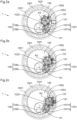
- a display mechanism 1 according to a first embodiment of the invention comprises a plate 100, a rocker 101, a date disk 1051, a day disk 1052, and means for controlling said rocker 101.
- Such a mechanism 1 is typically integrated into a watch movement, for example in a timepiece such as a pocket watch, a wristwatch, a clock or a clock.
- the date disc 1051 typically an annular disc, has a graduation 1061 comprising thirty-one indications, corresponding to the dates of the months, uniformly distributed over a circumference of its upper surface. These indications are arranged in ascending order in the opposite direction to the direction of rotation of the date disc 1051, that is to say in the counterclockwise direction, and are intended to move opposite an aperture 107 typically made in a dial of a timepiece in which the display mechanism 1 is integrated. In the figures 1a to 1c , the dial is not shown but the position of window 107 is shown.
- the date disc 1051 is typically carried by a ring 1021 with internal teeth comprising thirty-one teeth and called date ring 1021. It is for example glued, driven, screwed or brazed onto it. Alternatively, the date disc 1051 could directly include the internal teeth.
- the days disc 1052 comprises a graduation 1062 comprising seven indications corresponding to the names of the days of the week, these indications being uniformly distributed over a circumference of its upper surface. These indications 1062 are arranged according to the chronological order of the days in the opposite direction to the direction of rotation of the day disc 1052, that is to say clockwise and are intended to be read through the window 107 previously mentioned.
- the days disc 1052 is typically carried by a toothed wheel 1022 called the days wheel 1022. It is for example glued, driven, screwed or brazed onto it. Alternatively, the day disc could directly include the teeth.
- the date disk 1051 and the days disk 1052 allow the display of different temporal quantities and therefore have different rotation rates: a thirty-first turn per day for the date disk 1051 and a sixth of a turn per day for 1052 days disk.
- the rocker 101 is intended to pivot around an axis of rotation A1, fixed relative to the plate 100. It is driven in rotation around this axis A1 by means of an actuation mechanism 108 comprising a pinion actuation 108a and an actuation wheel 108b, as shown in figures 1a to 2c .
- the actuation pinion 108a is integral with the rocker 101 and meshes with the actuation wheel 108b, the rotational movements of which are controlled by the user by means of an actuation means not illustrated such as a rod, one end of which is accessible from outside the timepiece in which the mechanism 1 is integrated and the other end of which carries a rack meshing with the actuating wheel 108b.
- the assembly comprising said actuation mechanism 108 and actuation means constitutes the “control means” of the display mechanism 1.
- the rocker 101 Independently of the actuating pinion 108a, the rocker 101 carries a drive wheel 1031 comprising a first toothed wheel 1031a with sixty teeth and a second toothed wheel 1031b with six coaxial teeth, these wheels being integral in rotation with one of the other and free to rotate around axis A1.
- the first 1031a of the toothed wheels of this drive mobile 1031 is kinematically connected to the finishing gear of the watch movement in which the display mechanism 1 is integrated so that the two wheels 1031a, 1031b of this mobile typically complete a sixth of a turn every 24 hours.
- the second 1031b of the toothed wheels of this drive mobile 1031 meshes with the internal teeth of the date ring 1021. It takes one step every 24 hours and rotates said ring 1021 by one step every 24 hours, thus passing the date display from one indication to the next each day.
- the first 1031a of the wheels of said mobile 1031 meshes with the day wheel 1022 which is carried by the rocker 101.
- This day wheel 1022 is movable in rotation around an axis of rotation A2 distinct from the axis A1 and typically parallel to this axis A1, the axis A2 being fixed relative to the rocker 101 and movable in rotation relative to the plate 100.
- the gear ratio between this day wheel 1022 and the second wheel 1031b of the drive mobile 1031 is such that this day wheel 1022 is rotated at a rate of one seventh of a revolution per day.
- the actuation mechanism 108 When actuated, the actuation mechanism 108 makes it possible to pivot the rocker 101 between two extreme positions, alternately from a first to a second extreme position then from said second extreme position to said first extreme position.
- THE figures 2a to 2c illustrate the passage from the first of said extreme positions to the second of said extreme positions when the actuation mechanism 108 is actuated via the actuation means.
- There figure 2b represents an intermediate position between said two extreme positions.
- the end of the rocker 101 is close to the aperture 107 so that the days disc 1052 covers at least the part of the date disc 1051 located opposite the aperture 107, as illustrated in the figure 2c .
- the date disc 1051 is then no longer visible through the aperture 107.
- an indication of the graduation 1062 corresponding to the name of the day is entirely readable through this window 107, as at figure 2c .
- the two extreme positions that the rocker 101 takes during the operation of the display mechanism 1 define its angular movement. In this example, it is approximately 30°. These extreme positions are reached at each alternation of the direction of rotation of the rocker 101.
- the display mechanism 1 is designed so that the relative position of the rocker 101 relative to the plate 100 impacts neither the rotation of the days disc 1052 nor that of the date disc 1051. Indeed, the position of the center rotation A1 is fixed during the pivoting of the rocker 101 so that the first wheel 1031a of the drive mobile 1031 can be rotated continuously by the finishing gear.
- the second wheel 1031b of the drive mobile 1031 being integral with it, it is permanently able to drive the date disc 1051 in rotation.
- the day wheel 1022 and its axis of rotation A2 move with the rocker 101, this wheel 1022 therefore meshes with the first toothed wheel 1031a whatever the position of the rocker 101.
- the day disc 1052 is therefore rotated at a rhythm of one seventh of a revolution per day, whatever the position of the rocker 101.
- the display mechanism 1 operates in a dragging manner but it could easily be modified to operate instantly (by jumps), that is to say typically in a few milliseconds.
- the drive mobile 1031 could include an additional six-tooth star coaxial and integral in rotation with the first 1031a and second 1031b toothed wheels of the drive mobile 1031, this star being driven in instantaneous rotation of one step every 24 hours under the effect of a finger carried by a rocker carrying a feeler, said feeler being held against a spiral connected kinematically to the finishing gear of the watch movement in which said display mechanism 1 is integrated and dropping suddenly every 24 hours.
- the actuation means is typically designed to allow the day of the week to be displayed, either when it is held down or when it is held pulled.
- the actuating means can be designed to automatically return to its initial position or can, on the contrary, remain stuck in the position that the user has just imposed on it until it no longer activate it again.
- actuation means could be other than a rack rod as described above.
- this rack rod could for example be replaced by a connecting rod system.
- a connecting rod system would typically comprise a rod, one end of which would be accessible from outside the watch case and the other end of which would pivot freely around a fixed pin eccentrically on the actuating wheel 108b of the actuating mechanism 108 so as to cause the latter to rotate in one direction then in the other during its back and forth movements.
- the rack rod could be replaced by a rod, one end of which would be accessible from outside the watch case and another end of which would be fixed to a first end of a spring cable wound around the axis of rotation of the actuating wheel 108b.
- the second end of this spring cable would be fixed to said axis of rotation so that the back and forth movements of said rod would cause the wheel 108b to rotate alternately in one direction then in the other.
- Such a display mechanism 1 has the advantage of allowing the display of two different pieces of information, here different temporal quantities, alternately in the same window, the user being able, simply by acting on an actuation means, to control the flip-flop 101 to choose the information (date or day of the week) that he wishes to be able to read through the window 107. This allows, while offering the user the possibility of finding out about different information, to do not overload the dial with multiple windows.
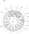
- a display mechanism 3 comprises a plate 300, a drive pinion 303 comprising twenty teeth pivoted on this plate and a support 301 on which a date display disc is pivoted 3051 secured to a date ring 3021 comprising three hundred and ten teeth, a disc day display 3052 integral with a day ring 3022 comprising one hundred and forty teeth, a date drive mobile 3041 and a day drive mobile 3042.
- the display mechanism 3 also includes a correction wheel 308 and a control means.
- Such a display mechanism 3 is typically integrated into a watch movement, for example a timepiece such as a pocket watch, a wristwatch, a clock or a clock.
- the date disk 3051 is typically an annular disk. It includes a graduation 3061 comprising thirty-one indications corresponding to the dates of the months ranging from 1 to 31, these indications being uniformly distributed over a circumference of its upper surface and intended to be read through an aperture 307 whose position is fixed relative to the plate 300.
- the window 307 is typically made in a dial positioned above the display discs 3051, 3052. In the figures 3 And 5a has 7 , the dial is not shown but the position of window 307 is shown.
- Days disc 3052 is typically an annular disc. It includes a graduation 3062 comprising fourteen indications corresponding to two series of the seven days of the week, these indications being uniformly distributed over a circumference of its upper surface and intended to be read through the aperture 307.
- the date disk 3051 and the days disk 3052 allow the display of different temporal quantities and therefore have different rotation rates: a thirty-first turn per day for the date disk 3051 and a fourteenth turn per day for the disk of days 1052. They rotate here in opposite directions.
- the date discs 3051 and days 3052 are concentric.
- the day disc has a diameter smaller than the diameter of the date disc and is arranged inside the latter.
- the day and date discs are therefore in the same plane, typically parallel to the plate 300.
- the display mechanism 3 allows, on command from a user, to manually change the disk 3051, 3052, the information of which can be read through the aperture 307.
- the support 301 and the drive mobiles 3041, 3042, the disks The display 3051, 3052 and the toothed rings 3021, 3022 which it carries are intended to pivot around an axis of rotation A7, coincident with the axis of rotation of the drive pinion 303, between two extreme positions, thus changing the indication readable through window 307. In this way, it can alternately show the day or the date.
- actuation means which controls an actuation mechanism that includes the display mechanism 3.
- This actuation mechanism includes an actuation rocker 309, first 310 and second 312 movable and a jumper 311, pivoted in the frame 300.
- the first mobile 310 comprises a star of seven teeth 310a and an actuating wheel with seventy teeth 310b coaxial and integral in rotation with one another. It is positioned by the jumper 311, the nose of which is held against the teeth of the star 310a by a spring (also not shown).
- the second mobile 312 comprises a twenty-tooth pinion 312a coaxial with axis A10 and integral in rotation with a circular board 312b carrying an eccentric pin 312c.
- actuation of the actuation means causes the pivoting of the rocker 309 in the counterclockwise direction.
- the torque exerted by the rocker 309 on the star 310a causes the lifting of the jumper 311 which allows a tooth of the star 310a to pass then repositions it.
- actuation of the actuating means causes the pivoting of one step of the star 310a and ten steps of the actuating wheel 310b in the clockwise direction.
- the actuating wheel 310b meshes with the pinion 312a of the second mobile 312, this causes the rotation of a half-turn of the second mobile 312 and its pin 312c around the axis A10.
- the support 301 comprises an oblong slot 301a in which the pin 312c of the second mobile 312 slides.
- This support 301 is also guided in rotation around the axis A7. It is typically capable of pivoting around the axis A7 during movements of the pin 312c in the oblong slot 301a, so that it only pivots during the rotation of the second mobile 312, that is to say when the actuation means is actuated.
- the support 301 as well as the drive mobiles 3041, 3042, display discs 3051, 3052 and toothed rings 3021, 3022 that it door pivot around the axis A7 in one direction then in the other between two extreme positions.
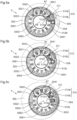
- the first of these extreme positions corresponds to the position illustrated in particular in figure 5a .
- part of the date disc 3051 is located opposite the aperture 307 so that one of the indications of the graduation 3061 corresponding to a date number, typically the indication "1", can be fully readable. through this window 307.
- This first extreme position of the support 301 corresponds to a “date disc reading position”.
- the second of these extreme positions corresponds to the position illustrated in particular in figure 5c .
- part of the days disc 3052 is located opposite the aperture 307 so that one of the indications of the graduation 3062 corresponding to a day of the week can be entirely readable through this aperture 307, typically the indication MON.
- This second extreme position of the support 301 corresponds to a “day disc reading position”.
- FIG. 5b illustrates one of the configurations in which the display mechanism 3 finds itself when the support 301 tilts between its two reading positions.
- the axes of rotation of the various members of the actuation mechanism are fixed relative to the plate 300 when moving from one reading position to another.
- the assembly comprising the actuation mechanism and the actuation means constitutes a “control means” of the mechanism 3.
- the display mechanism 3 is designed so that, whatever the reading position in which it is located, each day, typically instantly at midnight, the date disc 3051 makes a thirty-first turn in the clockwise direction and the days display disc 3052 makes a fourteenth turn in the counterclockwise direction around a common axis of rotation A6 fixed relative to the support 301 and corresponding to the common center of the date discs 3051 and the days 3052 considered in top view.
- This axis A6 being fixed relative to the support 301 it is obviously movable relative to the plate 300 when the user acts on the actuation means to change the reading position.
- the drive pinion 303 is kinematically connected to the finishing gear (not illustrated) of the watch movement in which the display mechanism 3 is integrated so as to instantly perform a half-turn in the counterclockwise direction (viewed from above). ) every day at midnight, as shown in figures 6a to 6c . The rest of the time, pinion 303 is stationary relative to plate 300.
- the drive pinion 303 When it pivots, the drive pinion 303 simultaneously rotates the date drive wheels 3041 and days 3042 which in turn cause the date display discs 3051 and days 3052 to rotate via their toothed rings 3021, 3022.
- the date drive mobile 3041 comprises a lower date wheel 3041a, an upper date wheel 3041b and a coaxial star 3041c with axis A8 as well as a jumper 3041d (on board) fixed to the upper date wheel 3041b and positioning the latter in relation to the star 3041c.
- the star 3041c of this mobile 3041 includes eight teeth and is integral with the lower date wheel 3041a which includes eighty teeth.
- the upper wheel 3041b is identical to the lower wheel 3041a and therefore also includes eighty teeth. It is free to rotate relative to the lower wheel 3041a and typically meshes with the teeth of the date ring 3021.
- the day drive wheel 3042 is, for its part, identical to the date drive wheel 3041, it comprises a lower date wheel 3042a, an upper date wheel 3042b and a coaxial star 3042c of axis A9 as well as a jumper 3042d (on board) fixed to the upper date wheel 3042b and positioning the latter in relation to the star 3042c.
- the star 3042c of this mobile 3042 includes eight teeth and is integral with the lower date wheel 3042b which includes eighty teeth.
- the upper wheel 3042b is identical to the lower wheel 3042a and therefore also includes eighty teeth. It is free to rotate relative to the lower wheel 3042a and meshes with the teeth of the day ring 3022.
- the drive pinion 303 meshes simultaneously with the lower wheels 3041a, 3042a of the display wheels 3041, 3042, respectively.
- the upper wheel 3041b then drives the date ring 3021 in rotation by ten steps in the clockwise direction, which corresponds to a rotation of one thirty-first turn of the date display disc 3051 around the axis A6 clockwise, as shown in figures 6a to 6c .
- the day drive mobile 3042 being identical to the date drive mobile 3041, parallel to its effect on the date display disc 3051, the rotation of the drive pinion 303 by a half-turn in the direction counterclockwise results in a rotation of the days ring 3022 by ten steps in the counterclockwise direction, which corresponds to a rotation of one fourteenth of a turn of the days display disc 3052 around the axis A6 in the counterclockwise direction, as illustrated in figures 6a to 6c .
- the drive pinion 303 causes a slight rotation of each of the display discs 3051, 3052 relative to the support 301 around the axis A6. This slight rotation is of course taken into account in the arrangement of the display discs 3051, 3052 relative to the aperture 307 so that, whatever the reading position of the display mechanism 3, a date indication 3061 or an indication of days 3062 is fully readable through window 307.
- the display mechanism 3 allows the correction of the date of the month and the day of the week independently, that is to say it allows the date to be corrected without impacting the day of the week and vice versa.
- the ring 3021 meshes with the upper wheel 3041b of the date drive mobile 3041, the latter is also rotated during date correction.
- the star 3041c is integral with the lower date wheel 3041a which meshes with the drive pinion 303 which is then stationary, the rotation of the upper date wheel 3041b does not cause the rotation of the star 3041c nor the wheel 3041a to which it is integral.
- the display mechanism 3 makes it possible to correct the date without correcting the day.
- the correction wheel 308 meshes with the day ring 3022 and allows, in the same way, to correct the day without correcting the date.
- the correction wheel 308 is typically operable from outside the timepiece in which the mechanism 3 is integrated, for example using a rod, one end of which is accessible from the outside of said part. watchmaking and the other end of which carries a toothed wheel meshing when the user wishes, for example in a pulled position, with the correction wheel 308.
- the assembly comprising the star of eight 3041c and the jumper 3041d of the date drive mobile 3041 ensures the positioning of the upper wheel 3041b of this mobile and of the date disc 3051 to which it is connected by gear with the toothed ring 3021 in an angular position in which a date indication can be fully visible through the aperture 307.
- a low intensity shock that is to say a shock generating a torque generating a slight rotation of the date disc 3051, typically a rotation of an angle corresponding to less than five teeth of the ring 2021 associated with the date disc , would ultimately have no impact. Indeed, such a slight rotation of the date disk 3051 would generate a rotation of the upper date wheel 3041b which would be insufficient for the jumper 3041d which it carries to skip a tooth of the date star 3041c. Under the effect of the restoring force of the spring of the jumper 3041d, the upper date wheel 3041b and the date disc 3051 would return to the place they occupied prior to the impact.
- the assembly comprising the star of eight 3041c and the jumper 3041d of the mobile 3041 makes it possible to ensure displacements of the date disc multiple by an angle of one thirty-one. first of a turn, so that an indication of the date graduation 3061 is fully readable through the aperture 307.
- a violent shock that is to say a shock generating a torque generating a strong rotation of the upper date wheel 3041b, typically a rotation of an angle corresponding to more than five teeth of the ring 2021 associated with the date disc , could impact the display.
- a strong rotation of the date disc 3051 could generate a rotation of the upper date wheel 3041b sufficient for the jumper 3041d that it carries to skip a tooth of the date star 3041c, in which case a change of the date display would occur similar to what happens during a voluntary correction of the date.
- the indication to be displayed remains centered in the aperture (no deindexing).
- the date drive wheels 3041 and days 3042 being identical, the assembly comprising the star of eight 3042c and the jumper 3042d of the days drive wheel 3042 ensures the positioning of the upper wheel 3042b of this wheel and the day disc 3052 to which it is connected via the day ring 3022 in an angular position in which an indication of the day graduation 3062 can be entirely visible through the aperture 307.
- the display mechanism 3 according to the second embodiment of the invention has the advantage of not requiring the superposition of the disks. This allows them to be positioned as close as possible under the dial for a better aesthetic appearance.
- Such a display mechanism 3 could typically be used to produce a display with changing the reading disk spontaneously several times during the day, to display first information over predefined time slots and other information the rest of the time. To do this, it would be enough to make the actuation of the rocker 309 automatic.
- the date drive mobile 3041 of the display mechanism 3 according to the second embodiment of the invention could be different from that presented with reference to the figures 3 to 7 .
- the star 3041c could be attached to the upper date wheel 3041b instead of being attached to the lower date wheel 3041a.
- the jumper 3041d, engaged in the teeth of the star 3041c would be fixed on the lower date wheel 3041a and not on the upper date wheel 3041b.
- the training mobile of days 3042 could be modified in the same way.
- this mechanism can be used as a drive mechanism for two discs simultaneously, independently of its capacity to allow the change of the disc whose information is readable through the aperture, that is to say typically without requiring support mobile such as the support 301 or control means for moving such a support.
- the toothed wheels of the drive wheels which respectively mesh with the rings with internal or external teeth are coplanar.
- they are located in the same plane as these rings, and in a space located between these rings 3021, 3022.
- a display mechanism 4 according to a third embodiment of the invention comprises a plate 400, a date disc 4051 and a day disc 4052, coaxial with axis A11 fixed relative to the plate 400.
- Such a mechanism 4 is typically integrated into a watch movement, for example in a timepiece such as a pocket watch, a wristwatch, a clock or a clock.
- the date disk 4051 is typically an annular disk. It includes a graduation 4061 comprising thirty-one indications corresponding to the dates of the months ranging from 1 to 31, these indications being uniformly distributed over a circumference of its upper surface and intended to be read through a main window 407 whose position is fixed relative to the plate 400. Its upper surface is therefore divided into thirty-one identical angular sectors typically of approximately 11.60°, each including an indication of the date graduation 4061.
- the main window 407 is typically made in a dial positioned over the discs 4051, 4052. In the figures 8a and 8b , the dial is not shown but the position of window 407 is shown.
- the days disc 4052 covers the date disc 4051. It is typically an annular disc. Its upper surface is divided into twenty-eight identical angular sectors 4022, typically of approximately 12.85° each. Every other angular sector 4022 includes an indication corresponding to a day of the week and each of the angular sectors 4022 not including an indication includes a secondary window 4011. The indications carried by the day disc form the graduation 4062 of the day disc 4052 and are partly visible through said secondary windows 4011.
- the day display disc 4052 therefore comprises a total of fourteen indications forming the graduation 4062, said indications being uniformly distributed on its upper surface and forming, in chronological order of days and counterclockwise, two series of indications of the seven days of the week, two consecutive indications of the days being separated by one of said secondary windows 4011.
- the main window 407 reveals a date indication or an indication of the day of the week.
- the display mechanism 4 includes two types of reading positions: a first grouping the reading positions of the date disk 4051 in which a secondary window 4011 of the days disk 4051 is aligned under the main window 407 so that an indication of the graduation 4061 of the date disc 4051 is entirely readable through the aperture 407, as in the example illustrated in figure 8a and a second grouping the reading positions of the days disc 4052 in which an indication of the graduation 4062 of the days disc 4052 is entirely readable through the aperture 407, as in the example illustrated in figure 8b .
- the display mechanism 4 allows, on command from a user, to manually change the disk 4051, 4052, the information of which is readable at through the window 407 by rotating the days disc 4052 to move from one type of reading position to another.
- the display mechanism 4 comprises a control means (not shown), typically accessible from outside the timepiece in which it is integrated, and allowing, when actuated, to rotate by a twenty-eighth turn the days display disc 4052 alternately in one direction then in the other.
- Such a control means allows for example during a first actuation the passage of the display mechanism 4 from the position illustrated to the figure 8a to the position shown in figure 8b by rotating the day display disc by a twenty-eighth turn clockwise then during a second actuation, the return of the mechanism 4 from the position illustrated in figure 8b to that illustrated in figure 8a by rotating the day display disc one twenty-eighth of a turn counterclockwise.
- the mechanism 4 is designed so that, whatever the type of reading position in which it is located, every day, typically instantly at midnight, the date display disc 4051 makes a thirty-first turn clockwise and the day display disc 4052 makes a fourteenth turn clockwise.
- a display mechanism 5 comprises a plate 500, a date disc 5051 and a concentric day disc 5052 with center A12 carrying indications respectively forming a date graduation 5061 and a graduation of the days 5062, said graduations 5061, 5062 being intended to be read through an aperture 507 fixed relative to the plate 500.
- This aperture 507 is typically produced in a dial positioned above the discs display 5051, 5052. In the figures 9a to 9b , this dial is not shown but the position of window 507 is shown.
- the date discs 5051 and the days 5052 are located in the same plane parallel to the plate 500. These are two annular discs.
- the days disc 5052 has a diameter smaller than the diameter of the date disc 5051 and is arranged inside the latter. The day and date discs are therefore in the same plane, typically parallel to the plate 500.
- Such a mechanism 5 is typically integrated into a watch movement, for example in a timepiece such as a pocket watch, a wristwatch, a clock or a clock.
- the display mechanism 5 allows, on command from a user, via a control means, to manually change the display disk 5051, 5052 whose information is readable through the window 507 by driving in translation the assembly comprising the date discs 5051 and days 5052 as well as their axis A12 parallel to the plate 500, between two extreme positions.
- the days disc 5052 is positioned outside the field visible through the aperture 507. It is typically intended to be almost completely or even completely under the dial.
- the date disc 5051 is positioned with a part facing the aperture 507 so that, when the relative position of the date disc 5051 relative to the aperture 507 allows it, an indication of the graduation 5061 corresponding to the date of the month is entirely readable through this window 507.
- This first extreme position corresponds to that illustrated in figure 9a and will be called “reading position of the date disc” in the remainder of the description of this embodiment.
- the date disc 5051 is positioned outside the field visible through the aperture 507. It is typically intended to be almost completely or even completely under the dial.
- the days disc 5052 is positioned partly opposite the aperture 507 so that, when the relative position of the days disc 5052 relative to the aperture 507 allows, an indication of the graduation 5062 corresponding to the day of the week is entirely readable through this window 507.
- This second extreme position corresponds to that of the figure 9b and will be called “days disc reading position” in the remainder of the description of this embodiment.
- the control means (not shown) of the mechanism 5 is typically accessible from outside the timepiece in which it is integrated. It allows for example, during a first actuation, the translational drive of the assembly comprising the date discs 5051 and days 5052 as well as their axis A12 from the position illustrated in the figure 9a to the position shown in figure 9b , then during a second actuation, the return of the mechanism 5 from the position illustrated in figure 9b to that illustrated in figure 9a by the reverse translation.
- the display mechanism 5 is designed so that, whatever the reading position in which it is located (reading position of the date disc or reading position of the days disc), every day, typically instantly at midnight , the date display disc 5051 makes a thirty-first turn clockwise and the days display disc 5052 makes a fourteenth turn counterclockwise around the axis A12.
- the display mechanism 5 is also designed so that the relative position of all the discs 5051, 5052 relative to the plate 500 impacts neither the daily rotation of the days disc 5052 nor that of the date disc 5051.
- the date display discs 5051 and days 5052 could typically be rotated by a mechanism similar to that according to the second embodiment of the invention.
- such a display mechanism 5 could typically be used to produce a display with change of the reading disc spontaneously.
- Still other display mechanisms for timepieces comprising several discs carrying indications intended to be read through a fixed aperture and allowing a user to manually change the disc whose information is readable through said aperture are possible. Examples of such mechanisms will be described below with reference to figures 10a to 11b .
- THE figures 10a to 10b And 11a to 11b respectively illustrate display mechanisms 6, 7 according to a fifth and a sixth embodiment of the invention.
- Each of the mechanisms 6, 7 comprises a plate 600, 700, a date disc 6051, 7051 comprising thirty-one indications corresponding to the date numbers and forming a graduation 6061, 7061, and a day disc 6052, 7052 comprising seven indications corresponding to the days of the week and forming a graduation 6062, 7062, said graduations 6061, 7061 being intended to be read through an aperture 607, 707 fixed relative to the plate 600, 700.
- Each of the windows 607, 707 is typically made in a dial positioned above the display discs of the mechanism 6, 7 concerned. In the figures 10a to 11b , the dials are not shown but the position of the windows 607, 707 is shown.
- the date disc 6051, 7051 and the days disc 6052, 7052 are located in the same plane, parallel to the plate 600, 700.
- the days disc 6052, 7052 and the date disc 6051, 7051 are capable of moving, on command from a user, together in translation in the case of mechanism 6 or separately in rotation around distinct centers of rotation in the case of mechanism 7, so as to make apparent through said window 607, 707, as desired, an indication of a graduation 6061, 7061 corresponding to the date of the current month or an indication of a graduation 6062, 7062 corresponding to the current day of the week.
- THE figures 10a and 10b respectively illustrate the two extreme positions that the days disc 6052 and the date disc 6051 can take when they move in translation, the figure 10a illustrating the reading position of the date disc 6051 and the figure 10b the disc reading position of days 6052.
- THE figures 11a and 11b respectively illustrate the two extreme positions that the date disc 7051 and the days disc 7052 can take when they move in rotation respectively around axes A15 and A16, the figure 11a illustrating the reading position of the date disc 7051 and the figure 11b the disc reading position of days 7052.
- Each of the display mechanisms 6, 7 is typically integrated into a watch movement, for example in a timepiece such as a pocket watch, a wristwatch, a clock or a clock.
- the display mechanism 6 is designed so that, whatever the reading position in which it is located, each day, typically instantly at midnight, the date display disc 6051 performs one thirty-first of turn clockwise around its axis of rotation A13 and the day display disc 6052 makes a seventh turn counterclockwise around its axis of rotation A14.
- the display mechanism 7 is designed so that, whatever the reading position in which it is located, every day, typically instantly at midnight, the date display disc 7051 performs a thirty-and-a-half hour. -first turn clockwise around its axis of rotation A17 and the days display disc 7052 makes a seventh turn counterclockwise around its axis of rotation A18.
- the display disks of the display mechanism according to the invention can allow the display of information other than the date or the day of the week. For example, names of the current day of the week and month, day of the week and number of the week, day of the week and moon age, day of the week and information according to which time it is morning or afternoon (AM/PM), the day of the week and a second time zone, the date of the month and the indication whether the year is a leap year or not, any indication and its translation into another language or any other combination of this information.
- chronograph information an equation of time
- a power reserve information relating to an alarm such as for example ON and OFF information, all information relating to the date and its derivatives or to a second or third time zone.
- more than two different pieces of information could be displayed alternately in the same window.
- the display mechanism according to the invention allows the display of at least two different pieces of information alternately in the same window. This allows, while offering the user the possibility of finding out about different information, not to overload the dial with multiple windows.
- control means can be manually operated by the user, the latter is able, by activating this control means, to change the information readable through the window at any time, at least occasionally.
- Such a mechanism can be particularly useful for displaying at least one additional piece of information, for example necessary for the operation of a perpetual calendar mechanism with a simple display (which only displays the date), for correction purposes only.
- the mechanism would then allow for example the display of the current month during its correction, this information being visible through the window only for its correction.
- the plate can be replaced by another frame, fixed or mobile, for example a bridge.
Landscapes
- Physics & Mathematics (AREA)
- General Physics & Mathematics (AREA)
- Electromechanical Clocks (AREA)
Applications Claiming Priority (3)
| Application Number | Priority Date | Filing Date | Title |
|---|---|---|---|
| EP18196793.6A EP3629102B1 (de) | 2018-09-26 | 2018-09-26 | Anzeigemechanismus mit einer fensteranzeige |
| EP19784144.8A EP3857313B1 (de) | 2018-09-26 | 2019-09-26 | Anzeigemechanismus mit einem einzigen fensterchen |
| PCT/IB2019/058176 WO2020065574A2 (fr) | 2018-09-26 | 2019-09-26 | Mécanisme d'affichage à guichet unique |
Related Parent Applications (2)
| Application Number | Title | Priority Date | Filing Date |
|---|---|---|---|
| EP19784144.8A Division EP3857313B1 (de) | 2018-09-26 | 2019-09-26 | Anzeigemechanismus mit einem einzigen fensterchen |
| EP19784144.8A Division-Into EP3857313B1 (de) | 2018-09-26 | 2019-09-26 | Anzeigemechanismus mit einem einzigen fensterchen |
Publications (2)
| Publication Number | Publication Date |
|---|---|
| EP4293431A2 true EP4293431A2 (de) | 2023-12-20 |
| EP4293431A3 EP4293431A3 (de) | 2024-02-28 |
Family
ID=63685662
Family Applications (3)
| Application Number | Title | Priority Date | Filing Date |
|---|---|---|---|
| EP18196793.6A Active EP3629102B1 (de) | 2018-09-26 | 2018-09-26 | Anzeigemechanismus mit einer fensteranzeige |
| EP19784144.8A Active EP3857313B1 (de) | 2018-09-26 | 2019-09-26 | Anzeigemechanismus mit einem einzigen fensterchen |
| EP23207985.5A Pending EP4293431A3 (de) | 2018-09-26 | 2019-09-26 | Anzeigemechanismus mit einem einzigen schalter |
Family Applications Before (2)
| Application Number | Title | Priority Date | Filing Date |
|---|---|---|---|
| EP18196793.6A Active EP3629102B1 (de) | 2018-09-26 | 2018-09-26 | Anzeigemechanismus mit einer fensteranzeige |
| EP19784144.8A Active EP3857313B1 (de) | 2018-09-26 | 2019-09-26 | Anzeigemechanismus mit einem einzigen fensterchen |
Country Status (5)
| Country | Link |
|---|---|
| US (1) | US12055897B2 (de) |
| EP (3) | EP3629102B1 (de) |
| JP (1) | JP7579241B2 (de) |
| CN (1) | CN112805634B (de) |
| WO (1) | WO2020065574A2 (de) |
Families Citing this family (4)
| Publication number | Priority date | Publication date | Assignee | Title |
|---|---|---|---|---|
| AU2019440423B2 (en) * | 2019-04-09 | 2023-03-02 | Hitachi Energy Ltd | Monitoring system for remotely monitoring a state of pole-mounted equipment in a power distribution or transmission grid, grid equipment having the monitoring system, and corresponding method |
| EP4189666A4 (de) * | 2020-07-29 | 2024-02-07 | Innocap Ltd. | Vorrichtung mit datumsanordnung |
| CH720138A2 (fr) * | 2022-10-18 | 2024-04-30 | Goujon Pierre | Dispositif d'affichage d'indications discrètes |
| EP4567528A1 (de) * | 2023-12-08 | 2025-06-11 | Blancpain SA | Uhrwerk mit einem mechanismus zur anzeige der perioden eines jahreszyklus, das durch ein 31-mobil gesprungt wird |
Family Cites Families (21)
| Publication number | Priority date | Publication date | Assignee | Title |
|---|---|---|---|---|
| DE738177C (de) | 1938-06-21 | 1943-08-05 | Peter Guenther Wachtel | 24-Stundenuhr |
| CH550425A (de) * | 1966-01-11 | 1974-06-14 | ||
| CH556562B (fr) * | 1971-08-20 | 1974-11-29 | Bandi Fred | Dispositif d'indication du quantieme et du jour de la semaine pour instrument de mesure du temps. |
| DE69112609T2 (de) | 1990-12-14 | 1996-04-04 | Rolex Montres | Armbanduhr. |
| CH684920B5 (fr) * | 1993-08-31 | 1995-08-15 | Ebauchesfabrik Eta Ag | Pièce d'horlogerie. |
| CH687796B5 (fr) * | 1994-05-30 | 1997-08-31 | Vincent Calabrese | Mecanisme d'horlogerie pour affichage alternatif des 24 heures. |
| CH691088A5 (fr) * | 1997-03-27 | 2001-04-12 | Girard Perregaux Sa | Mécanisme de mise à l'heure d'un mouvement d'horlogerie à quantième perpétuel. |
| EP1184751A1 (de) * | 2000-08-23 | 2002-03-06 | Eta SA Fabriques d'Ebauches | Elektronische Uhr mit Datumanzeige durch ein grosses Fenster |
| CH695712A5 (fr) * | 2001-09-24 | 2006-07-31 | Richemont Int Sa | Mécanisme d'affichage d'un nombre avec deux chiffres. |
| CH695397A5 (fr) * | 2002-04-15 | 2006-04-28 | Richemont Int Sa | Dispositif d'affichage du quantième. |
| EP1406131A1 (de) * | 2002-10-01 | 2004-04-07 | Manufacture Roger Dubuis S.A. | Mechanische Vorrichtung zur Anzeige von Stunden und Minuten |
| EP1536299B1 (de) | 2003-11-26 | 2010-05-19 | ETA SA Manufacture Horlogère Suisse | Kalendermechanismus für eine Uhr mit zwei übereinanderliegenden Ringen |
| WO2006106787A1 (ja) * | 2005-03-30 | 2006-10-12 | Citizen Holdings Co., Ltd. | 表示装置および時計のカレンダ装置 |
| CH704343B1 (fr) | 2007-09-28 | 2012-07-13 | Franck Mueller Watchland Sa | Dispositif d'affichage des mois pour mouvement horloger. |
| CN201181402Y (zh) * | 2008-03-31 | 2009-01-14 | 天津海鸥表业集团有限公司 | 手表同轴式大日历显示机构 |
| EP2180383B1 (de) | 2008-10-24 | 2012-01-25 | ETA SA Manufacture Horlogère Suisse | Hilfsvorrichtung zur Positionshaltung einer Datumsanzeigescheibe für Uhrwerk |
| CH707971B8 (fr) * | 2013-04-29 | 2017-09-15 | Télôs Watch SA | Pièce d'horlogerie comprenant un dispositif d'affichage de quantième. |
| EP2835697B1 (de) * | 2013-08-05 | 2022-01-05 | ETA SA Manufacture Horlogère Suisse | Vorrichtung zur Anzeige einer Datumsanzeige |
| EP3032357B1 (de) | 2014-12-09 | 2017-05-03 | The Swatch Group Research and Development Ltd. | Anzeigevorrichtung für ein tragbares Instrument, wie beispielsweise eine Uhr |
| EP3173876B1 (de) * | 2015-11-26 | 2020-09-02 | Rolex Sa | Kalendersystem für uhr |
| EP3779609B1 (de) * | 2019-08-13 | 2022-03-16 | Patek Philippe SA Genève | Anzeigemechanismus für uhr |
-
2018
- 2018-09-26 EP EP18196793.6A patent/EP3629102B1/de active Active
-
2019
- 2019-09-26 WO PCT/IB2019/058176 patent/WO2020065574A2/fr not_active Ceased
- 2019-09-26 JP JP2021516767A patent/JP7579241B2/ja active Active
- 2019-09-26 EP EP19784144.8A patent/EP3857313B1/de active Active
- 2019-09-26 EP EP23207985.5A patent/EP4293431A3/de active Pending
- 2019-09-26 US US17/279,992 patent/US12055897B2/en active Active
- 2019-09-26 CN CN201980063729.4A patent/CN112805634B/zh active Active
Also Published As
| Publication number | Publication date |
|---|---|
| US20210397132A1 (en) | 2021-12-23 |
| JP2022502640A (ja) | 2022-01-11 |
| WO2020065574A3 (fr) | 2020-07-02 |
| US12055897B2 (en) | 2024-08-06 |
| JP7579241B2 (ja) | 2024-11-07 |
| EP3629102B1 (de) | 2022-12-14 |
| CN112805634A (zh) | 2021-05-14 |
| EP3857313B1 (de) | 2024-02-07 |
| WO2020065574A2 (fr) | 2020-04-02 |
| EP4293431A3 (de) | 2024-02-28 |
| EP3857313A2 (de) | 2021-08-04 |
| EP3629102A1 (de) | 2020-04-01 |
| CN112805634B (zh) | 2023-06-27 |
Similar Documents
| Publication | Publication Date | Title |
|---|---|---|
| EP1586962B9 (de) | Perpetual calendar mechanism | |
| EP3857313B1 (de) | Anzeigemechanismus mit einem einzigen fensterchen | |
| EP0940833A1 (de) | Kalendermechanismus für Uhrwerk | |
| EP1536299B1 (de) | Kalendermechanismus für eine Uhr mit zwei übereinanderliegenden Ringen | |
| CH714690A2 (fr) | Mécanisme de calendrier, mouvement et pièce d’horlogerie. | |
| EP2720090B1 (de) | Universaluhr | |
| EP3570119A1 (de) | Anzeigemechanismus eines sich periodisch wiederholenden ereignisses, und mit einem solchen mechanismus ausgestattete uhr | |
| CH690515A5 (fr) | Pièce d'horlogerie munie d'un affichage du quantième. | |
| WO1998044394A1 (fr) | Mecanisme de mise a l'heure d'un mouvement d'horlogerie a quantieme perpetuel | |
| EP4254079B1 (de) | Mechanismus zur anzeige der mondphasen für uhr | |
| EP3739395B1 (de) | Anzeigesystem der gezeiten | |
| EP3460588B1 (de) | Datumsmechanismus | |
| EP2689299B1 (de) | Träger für das anzeigeelement eines uhrwerks | |
| EP4462192B1 (de) | Anzeigevorrichtung für uhrwerk | |
| EP0629932A1 (de) | Uhr mit mindestens einer durch die Datumsanzeige getriebenen drehbarer Anzeigevorrichtung | |
| EP3667435A1 (de) | Einstellsystem der position eines ersten gezahnten drehteils in bezug auf eine halterung, auf der dieses erste gezahnte drehteil drehbar befestigt ist, und uhr, die ein solches system umfasst | |
| CH721374A2 (fr) | Mouvement d'horlogerie comportant un mécanisme d'affichage des périodes d'un cycle annuel animé par un anneau de quantième | |
| EP1729185B1 (de) | Uhr mit einer Vorrichtung zur Anzeige des Wochenranges im aktuellen Jahr | |
| CH719176B1 (fr) | Mécanisme d'affichage pour pièce d'horlogerie | |
| CH719557B1 (fr) | Mécanisme d'affichage des phases de lune de pièce d'horlogerie | |
| EP4361739A1 (de) | Funktionsauswahlsystem für eine uhr | |
| CH720897A2 (fr) | Mécanisme de quantième | |
| CH718804A1 (fr) | Mécanisme de quantième perpétuel ou annuel. | |
| CH718698A1 (fr) | Mécanisme horloger pour correction de plusieurs affichages. | |
| WO2006108878A1 (fr) | Mecanisme d'affichage sautant de l’heure pour piece d’horlogerie |
Legal Events
| Date | Code | Title | Description |
|---|---|---|---|
| PUAI | Public reference made under article 153(3) epc to a published international application that has entered the european phase |
Free format text: ORIGINAL CODE: 0009012 |
|
| STAA | Information on the status of an ep patent application or granted ep patent |
Free format text: STATUS: THE APPLICATION HAS BEEN PUBLISHED |
|
| AC | Divisional application: reference to earlier application |
Ref document number: 3857313 Country of ref document: EP Kind code of ref document: P |
|
| AK | Designated contracting states |
Kind code of ref document: A2 Designated state(s): AL AT BE BG CH CY CZ DE DK EE ES FI FR GB GR HR HU IE IS IT LI LT LU LV MC MK MT NL NO PL PT RO RS SE SI SK SM TR |
|
| PUAL | Search report despatched |
Free format text: ORIGINAL CODE: 0009013 |
|
| AK | Designated contracting states |
Kind code of ref document: A3 Designated state(s): AL AT BE BG CH CY CZ DE DK EE ES FI FR GB GR HR HU IE IS IT LI LT LU LV MC MK MT NL NO PL PT RO RS SE SI SK SM TR |
|
| RIC1 | Information provided on ipc code assigned before grant |
Ipc: G04B 19/247 20060101AFI20240122BHEP |
|
| STAA | Information on the status of an ep patent application or granted ep patent |
Free format text: STATUS: REQUEST FOR EXAMINATION WAS MADE |
|
| 17P | Request for examination filed |
Effective date: 20240813 |
|
| RBV | Designated contracting states (corrected) |
Designated state(s): AL AT BE BG CH CY CZ DE DK EE ES FI FR GB GR HR HU IE IS IT LI LT LU LV MC MK MT NL NO PL PT RO RS SE SI SK SM TR |
|
| P01 | Opt-out of the competence of the unified patent court (upc) registered |
Free format text: CASE NUMBER: APP_32254/2025 Effective date: 20250703 |
|
| STAA | Information on the status of an ep patent application or granted ep patent |
Free format text: STATUS: EXAMINATION IS IN PROGRESS |
|
| 17Q | First examination report despatched |
Effective date: 20251107 |