EP4293820A1 - Ensemble antenne, système d'antenne et véhicule - Google Patents
Ensemble antenne, système d'antenne et véhicule Download PDFInfo
- Publication number
- EP4293820A1 EP4293820A1 EP22752221.6A EP22752221A EP4293820A1 EP 4293820 A1 EP4293820 A1 EP 4293820A1 EP 22752221 A EP22752221 A EP 22752221A EP 4293820 A1 EP4293820 A1 EP 4293820A1
- Authority
- EP
- European Patent Office
- Prior art keywords
- antenna
- sunroof
- cables
- vehicle
- radiators
- Prior art date
- Legal status (The legal status is an assumption and is not a legal conclusion. Google has not performed a legal analysis and makes no representation as to the accuracy of the status listed.)
- Pending
Links
Images


Classifications
-
- H—ELECTRICITY
- H01—ELECTRIC ELEMENTS
- H01Q—ANTENNAS, i.e. RADIO AERIALS
- H01Q1/00—Details of, or arrangements associated with, antennas
- H01Q1/27—Adaptation for use in or on movable bodies
- H01Q1/32—Adaptation for use in or on road or rail vehicles
- H01Q1/325—Adaptation for use in or on road or rail vehicles characterised by the location of the antenna on the vehicle
- H01Q1/3275—Adaptation for use in or on road or rail vehicles characterised by the location of the antenna on the vehicle mounted on a horizontal surface of the vehicle, e.g. on roof, hood, trunk
-
- H—ELECTRICITY
- H01—ELECTRIC ELEMENTS
- H01Q—ANTENNAS, i.e. RADIO AERIALS
- H01Q1/00—Details of, or arrangements associated with, antennas
- H01Q1/12—Supports; Mounting means
- H01Q1/22—Supports; Mounting means by structural association with other equipment or articles
-
- H—ELECTRICITY
- H01—ELECTRIC ELEMENTS
- H01Q—ANTENNAS, i.e. RADIO AERIALS
- H01Q1/00—Details of, or arrangements associated with, antennas
- H01Q1/27—Adaptation for use in or on movable bodies
- H01Q1/32—Adaptation for use in or on road or rail vehicles
- H01Q1/3208—Adaptation for use in or on road or rail vehicles characterised by the application wherein the antenna is used
- H01Q1/3233—Adaptation for use in or on road or rail vehicles characterised by the application wherein the antenna is used particular used as part of a sensor or in a security system, e.g. for automotive radar, navigation systems
-
- H—ELECTRICITY
- H01—ELECTRIC ELEMENTS
- H01Q—ANTENNAS, i.e. RADIO AERIALS
- H01Q1/00—Details of, or arrangements associated with, antennas
- H01Q1/36—Structural form of radiating elements, e.g. cone, spiral, umbrella; Particular materials used therewith
-
- H—ELECTRICITY
- H01—ELECTRIC ELEMENTS
- H01Q—ANTENNAS, i.e. RADIO AERIALS
- H01Q1/00—Details of, or arrangements associated with, antennas
- H01Q1/36—Structural form of radiating elements, e.g. cone, spiral, umbrella; Particular materials used therewith
- H01Q1/38—Structural form of radiating elements, e.g. cone, spiral, umbrella; Particular materials used therewith formed by a conductive layer on an insulating support
-
- H—ELECTRICITY
- H01—ELECTRIC ELEMENTS
- H01Q—ANTENNAS, i.e. RADIO AERIALS
- H01Q1/00—Details of, or arrangements associated with, antennas
- H01Q1/48—Earthing means; Earth screens; Counterpoises
-
- H—ELECTRICITY
- H01—ELECTRIC ELEMENTS
- H01Q—ANTENNAS, i.e. RADIO AERIALS
- H01Q1/00—Details of, or arrangements associated with, antennas
- H01Q1/50—Structural association of antennas with earthing switches, lead-in devices or lightning protectors
-
- H—ELECTRICITY
- H01—ELECTRIC ELEMENTS
- H01Q—ANTENNAS, i.e. RADIO AERIALS
- H01Q21/00—Antenna arrays or systems
-
- H—ELECTRICITY
- H01—ELECTRIC ELEMENTS
- H01Q—ANTENNAS, i.e. RADIO AERIALS
- H01Q21/00—Antenna arrays or systems
- H01Q21/0006—Particular feeding systems
-
- H—ELECTRICITY
- H01—ELECTRIC ELEMENTS
- H01Q—ANTENNAS, i.e. RADIO AERIALS
- H01Q21/00—Antenna arrays or systems
- H01Q21/28—Combinations of substantially independent non-interacting antenna units or systems
-
- H—ELECTRICITY
- H01—ELECTRIC ELEMENTS
- H01Q—ANTENNAS, i.e. RADIO AERIALS
- H01Q9/00—Electrically-short antennas having dimensions not more than twice the operating wavelength and consisting of conductive active radiating elements
- H01Q9/04—Resonant antennas
- H01Q9/0407—Substantially flat resonant element parallel to ground plane, e.g. patch antenna
- H01Q9/045—Substantially flat resonant element parallel to ground plane, e.g. patch antenna with particular feeding means
- H01Q9/0457—Substantially flat resonant element parallel to ground plane, e.g. patch antenna with particular feeding means electromagnetically coupled to the feed line
Definitions
- This disclosure relates to the field of antenna technology, and in particular, to an antenna assembly, an antenna system, and a vehicle.
- An existing antenna assembly is generally mounted in a shark fin, and the shark fin may integrate multiple antennas and be mounted on the roof of the vehicle.
- external antennas disposed on the outside of the vehicle affects exterior design of the vehicle, and if design of external antennas is unreasonable, an air resistance to the vehicle may increase.
- An antenna assembly, an antenna system, and a vehicle are provided in the disclosure.
- the antenna assembly When the antenna assembly is applied to the vehicle, exterior design of the vehicle may not be affected.
- an antenna assembly applicable to a vehicle includes a sunroof and an antenna combination.
- the antenna combination is disposed at an end of the sunroof.
- the antenna combination includes multiple antenna elements arranged along an edge of the sunroof.
- the multiple antenna elements include a first antenna element.
- the first antenna element is a navigation antenna element and includes a first radiator disposed at a central axis of the sunroof.
- the multiple antenna elements further include a second antenna element.
- the second antenna element includes multiple second radiators arranged along the edge of the sunroof.
- the multiple antenna elements further include a third antenna element.
- the third antenna element includes multiple third radiators arranged along the edge of the sunroof.
- the multiple antenna elements include radiators and first cables.
- the sunroof includes an inner layer, an intermediate layer, and an outer layer that are stacked in sequence.
- the radiators are disposed between the inner layer and the outer layer, and the first cables are disposed at a side of the inner layer away from the radiators.
- the multiple antenna elements further include a ground layer disposed at a side of the inner layer away from the outer layer.
- the ground layer defines a gap thereon. Orthographic projections of the first cables on the ground layer at least partially fall within the gap.
- the first cables are coupled to and configured to feed the radiators through the gap on the ground layer.
- the multiple antenna elements include radiators, a ground layer, and first cables.
- the radiators and the ground layer are disposed at a same side of the sunroof, and the first cables are directly connected to and configured to feed the radiators.
- the antenna assembly further includes a fixing member.
- the multiple antenna elements include radiators and first cables.
- the first cables are electrically connected to the radiators, and the first cables are fixed on the sunroof through the fixing member.
- the first cables are implemented as multiple first cables, and the multiple first cables are arranged at intervals along the edge of the sunroof.
- an antenna system is further provided in the disclosure.
- the antenna system includes an on-board unit (OBU) and the antenna assembly above.
- the first cables of the antenna assembly are electrically connected to the OBU.
- OBU on-board unit
- a vehicle in a third aspect, is further provided in the disclosure.
- the vehicle includes a vehicle body and the antenna system above.
- the antenna system is mounted on the vehicle body, and the OBU of the antenna system is electrically connected to the vehicle body through a second cable.
- the antenna assembly provided in the disclosure can bring the following technical effects.
- the antenna combination is disposed on the sunroof, so that adverse effect on exterior design of the vehicle can be avoided, and an air resistance may not be increased.
- the antenna combination is disposed at the edge of the sunroof, which can avoid or weaken light blocking by the antenna combination, thereby ensuring that sufficient light can pass through the sunroof and then irradiate the interior of the vehicle, so as to obtain better daylighting effect.
- the multiple antenna elements are arranged along the edge of the sunroof, so that a length direction of the OBU can be designed to be parallel to a direction in which the multiple antenna elements are arranged. Under such arrangement, a connection area between the OBU and the vehicle body can be increased, thereby improving connection stability and facilitating arrangement of the first cables between the OBU and the multiple antenna elements.
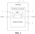
- FIG. 1 is a schematic top view of an antenna assembly provided in an implementation of the disclosure.
- a vehicle 1 is provided in the disclosure.
- the vehicle 1 may be, but is not limited to, a sedan, a multi-purpose vehicle (MPV), a sports/suburban utility vehicle (SUV), an off-road vehicle (ORV), a pickup, a minibus, a passenger vehicle, a cargo vehicle, and the like.
- MPV multi-purpose vehicle
- SUV sports/suburban utility vehicle
- ORV off-road vehicle
- pickup a minibus
- passenger vehicle a cargo vehicle, and the like.
- the vehicle 1 includes a vehicle body 2 and an antenna system 3 that will be described in the following implementations.
- the antenna system 3 is mounted on the vehicle body 2, and an on-board unit (OBU) 5 of the antenna system 3 is electrically connected to the vehicle body 2 through a second cable 4.
- OBU on-board unit
- the vehicle body 2 refers to at least part of the vehicle 1, or the vehicle body 2 may include at least part of structural members and electronic components of the vehicle 1.
- the vehicle body 2 may include a frame, a windshield, a seat, a central control screen, and the like.
- the antenna system 3 is configured to transmit/receive (i.e., transmit and/or receive) an electromagnetic wave.
- the OBU 5 of the antenna system 3 is electrically connected to the vehicle body 2 via the second cable 4 (a power-supply line 41 and a communication line 42).
- the OBU 5 is connected to a vehicle network via the second cable 4 for communication, and the vehicle 1 is communicated with the outside via the antenna system 3.
- the antenna system 3 is further provided in the disclosure.
- the antenna system 3 includes the OBU 5 and an antenna assembly 6 described in any one of the following implementations.
- a first cable 250 of the antenna assembly 6 is electrically connected to the OBU 5.
- the OBU 5 may be disposed at a component such as the windshield, the frame, or a ceiling of the vehicle 1, which is not limited herein.
- the OBU 5 is configured to generate a radio-frequency (RF) signal.
- the RF signal may be transmitted to the antenna assembly 6 through the first cable 250 to excite the antenna assembly 6 to generate a corresponding electromagnetic wave and radiate the electromagnetic wave to a surrounding space, in this case, the antenna system 3 transmits an electromagnetic wave.
- the antenna system 3 can also receive an electromagnetic wave. A process of receiving the electromagnetic wave is opposite to the foregoing process.
- the first cable 250 can be electrically connected to the OBU 5 in a pluggable manner via a connector.
- the antenna assembly 6 and the OBU 5 can be produced separately, which is beneficial to reducing production and processing difficulty and improving production efficiency.
- the first cable 250 can be mounted to be connected to the OBU 5 only when the vehicle body 2 needs to use the antenna system 3, thereby avoiding break of a connection between the first cable 250 and the OBU 5 due to external factors during transportation, selling, and the like.
- the antenna assembly 6 is further provided in the disclosure.
- the antenna assembly 6 includes a sunroof 10 and an antenna combination 20.
- the sunroof 10 may be a glass mounted on a top of the vehicle 1.
- the sunroof 10 may be in a shape including, but not limited to, a square, a rectangle, a triangle, an oval, a circle, and the like.
- the antenna combination 20 is disposed at an end of the sunroof 10.
- the end of the sunroof 10 refers to a portion of the sunroof 10 adjacent to an edge of the sunroof 10.
- the sunroof 10 has multiple ends.
- the antenna combination 20 may be disposed at any one of the multiple ends of the sunroof 10. For example, a rectangular sunroof has four ends, and the antenna combination 20 may be disposed at any one of the four ends.
- a coordinate system is introduced in a view in which the antenna assembly 6 is illustrated in FIG. 4 .
- a width direction of the sunroof 10 is defined as an X-axis direction
- a length direction of the sunroof 10 is defined as a Y-axis direction (which is also a length direction or a driving direction of the vehicle 1)
- a direction perpendicular to an X-O-Y plane is defined as a Z-axis direction (which is a thickness direction of the sunroof 10 as well as an irradiation direction of light).
- the antenna combination 20 includes multiple antenna elements 200 operating in different frequency ranges.
- Term “multiple” means that the number (quantity) is greater than or equal to two, specifically, the number may be 2, 3, 5, 6, etc.
- the antenna element 200 may be, but is not limited to, a frequency modulation (FM)/amplitude modulation (AM) antenna, a television (TV) antenna, a telephone antenna, a navigation antenna, a Bluetooth antenna, a 5 th generation (5G) antenna, a vehicle-to-everything (V2X) antenna, etc.
- FM frequency modulation
- AM amplitude modulation
- the multiple antenna elements 200 are arranged along the edge of the sunroof 10, that is, the multiple antenna elements 200 are arranged in sequence in the X-axis direction in FIG. 4 . In other implementations, the multiple antenna elements 200 may be arranged in sequence in the Y-axis direction in FIG. 4 . It can be understood that, an extending direction of the edge of the sunroof 10 is related to the shape of the sunroof 10 itself, and a direction in which the multiple antenna elements 200 are arranged may also change accordingly. Exemplarily, in the case where the shape of the sunroof 10 is a circle, the edge of the sunroof 10 extends in an arc-shaped direction, and the multiple antenna elements 200 may be accordingly arranged in an arc-shaped direction. In the case where the shape of the sunroof 10 is a rectangle (as illustrated in FIG. 4 ), the edge of the sunroof 10 may extend alone a straight line, and the multiple antenna elements 200 may be arranged along the straight line accordingly.
- the antenna combination 20 is disposed on the sunroof 10, so that adverse effect on exterior design of the vehicle 1 can be avoided, and an air resistance may not be increased.
- the antenna combination 20 is disposed at the edge of the sunroof 10, which can avoid or weaken light blocking by the antenna combination 20, thereby ensuring that sufficient light can pass through the sunroof 10 and then irradiate the interior of the vehicle 1, so as to obtain better daylighting effect.
- the multiple antenna elements 200 are arranged along the edge of the sunroof 10, so that a length direction of the OBU 5 can be designed to be parallel to the direction in which the multiple antenna elements 200 are arranged. Under such arrangement, a connection area between the OBU 5 and the vehicle body 2 can be increased, thereby improving connection stability and facilitating arrangement of the first cables 250 between the OBU 5 and the multiple antenna elements 200.
- the multiple antenna elements 200 include radiators 240, a ground layer 260, and first cables 250.
- the radiator 240 is configured to transmit/ receive an electromagnetic wave.
- the radiator 240 may be formed on the sunroof 10 through a process including, but not limited to, silver paste printing or coating.
- the radiators 240 include a first radiator 211, a second radiator 221, and a third radiator 231.
- the three radiators 240 belong to different antenna elements 200, which will be described in the following implementations.
- the ground layer 260 is configured to provide a reference ground plane for the radiator 240, and the ground layer 260 may be formed on the sunroof 10 through a process including, but not limited to, silver paste printing.
- the first cable 250 is configured to be electrically connected to the OBU 5 and the radiator 240.
- the first cable 250 includes an insulation sleeve 251 and a core 252.
- the core 252 is wrapped in the insulation sleeve 251.
- the insulation sleeve 251 is connected to the ground layer 260, and the core 252 is configured to feed the radiator 240.
- the antenna combination 20 further includes a fixing member 270.
- the first cable 250 is fixed on one side of the sunroof 10 through the fixing member 270. It can be understood that, an inevitable vibration of the vehicle 1 during driving of the vehicle 1 may cause the first cable 250 to shake, and several times of shaking of the first cable 250 may eventually cause the first cable 250 to fall off from the sunroof 10.
- the fixing member 270 the first cable 250 can be fixed on the sunroof 10 through the fixing member 270, which can prevent the first cables 250 between the fixing member 270 and the radiators 240 from excessive shaking, thereby solving the foregoing problem.
- the multiple first cables 250 are arranged in a distributed manner. It can be understood that, if the multiple first cables 250 are bound together to form a cable combination, the cable combination has relatively great inertia compared with a single first cable 250. During shaking of the cable combination, a single first cable 250 in the cable combination is subject to a relatively large pulling force, which may cause a joint of the first cable 250 to be torn off under long-term action of the relatively large pulling force. Compared with the manner of binding the multiple first cables 250 together, in the implementations, the multiple first cables 250 are arranged in the distributed manner to avoid a relatively large force of inertia, thereby overcoming the foregoing problem.
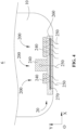
- the sunroof 10 includes an inner layer 110, an intermediate layer 120, and an outer layer 130 that are stacked in sequence.
- the inner layer 110 is one layer of the sunroof 10 exposed inside the vehicle 1, and the inner layer 110 may be made of a material including, but not limited to, glass.
- the intermediate layer 120 is an interlayer material sandwiched between the inner layer 110 and the outer layer 130, and is used to bond the inner layer 110 and the outer layer 130 together.
- the intermediate layer 120 may be made of a material including, but not limited to, polyvinyl butyral (PVB).
- the outer layer 130 is one layer of the sunroof 10 exposed outside the vehicle 1, and the outer layer 130 may be made of a material including, but not limited to, glass.
- the first cable 250 is coupled to and configured to feed the radiator 240.
- the radiator 240 is disposed between the inner layer 110 and the outer layer 130, and the first cable 250 and the ground layer 260 each are disposed at a side of the inner layer 110 away from the radiator 240.
- the ground layer 260 defines a gap C1.
- An orthographic projection of the first cable 250 on the ground layer 260 at least partially falls within the gap C1. That is, the orthographic projection of the first cable 250 on the ground layer 260 intersects the gap C1, so that the first cable 250 is coupled to and configured to feed the radiator 240 through the gap C1 on the ground layer 260.
- the gap C1 may be in a shape including, but not limited to, a square, a rectangle, a circle, etc., where the shape and size of the gap C1 are not limited herein. It can be understood that, coupling-feeding may widen a bandwidth of the antenna element 200, that is, increase a frequency range of an effective operation of the antenna element 200.
- the radiator 240 may be disposed between the inner layer 110 and the intermediate layer 120.
- the radiator 240 may be formed on a surface of the inner layer 110 close to the outer layer 130 through silver paste printing or coating.
- the radiator 240 may also be disposed between the outer layer 130 and the intermediate layer 120. In implementations of the disclosure, only an example that the radiator 240 is disposed between the inner layer 110 and the intermediate layer 120 is taken for exemplary illustration.
- the radiator 240 being disposed between the inner layer 110 and the outer layer 130 can realize conformal antennas without affecting the structure of the sunroof 10
- the radiator 240 being disposed between the inner layer 110 and the outer layer 130 can prevent the radiator 240 from external interference and break, thereby facilitating the antenna combination 20 to stably realize a corresponding function.
- the radiator 240 and the ground layer 260 are disposed on a same side of the sunroof 10, and the first cable 250 is directly connected to and configured to feed the radiator 240.
- the radiator 240 and the ground layer 260 each are disposed on a surface of the inner layer 110 away from the outer layer 130.
- the ground layer 260 defines the gap C1
- the radiator 240 is received in the gap C1
- the first cable 250 may be connected to the radiator 240 through a process including, but not limited to, welding, and such a structure may be referred to as a coplanar waveguide structure.
- the radiator 240 and the ground layer 260 each are disposed on the surface of the inner layer 110 away from the outer layer 130, which avoids a problem in the above coupling-feeding that two opposite sides of the inner layer 110 need to be separately processed, thereby improving processing efficiency, moreover, also avoids a problem that the radiator 240 may be damaged by being pulled or pressed by the intermediate layer 120.
- the multiple antenna elements 200 include a first antenna element 210, a second antenna element 220, and a third antenna element 230, where each element will be described in detail below with reference to the accompanying drawings.
- the first antenna element 210 is a navigation antenna element, where the navigation antenna element can receive positioning information to determine a current position of the vehicle 1.
- the first antenna element 210 includes a first radiator 211 and a first cable 250.
- the OBU 5 is electrically connected to the first radiator 211 via the first cable 250.
- the first cable 250 is coupled to and configured to feed the first radiator 211, or the first cable 250 is directly connected to and configured to feed the first radiator 211 (for details, reference can be made to the foregoing implementations).
- a geometric center of the first radiator 211 is located at a central axis of the sunroof 10. It can be understood that the sunroof 10 is also generally disposed at the central axis of the vehicle 1, that is to say, the geometric center of the first radiator 211 is located at or approximately located at the central axis of the vehicle 1. Since the first antenna element 210 is a navigation antenna element, the positioning information of the vehicle 1 is based on a position of the first antenna element 210, and thus the first radiator 211 disposed at the central axis of the sunroof 10 can make the positioning of the vehicle 1 more accurate.
- the first antenna element 210 is not disposed at the central axis of the vehicle 1, during a U-turn in place, a positioning point of the vehicle 1 before the U-turn is located at one side of the central axis of the vehicle 1, while a positioning point of the vehicle 1 after the U-turn is located at the other side of the central axis of the vehicle 1. That is to say, at the same location and different orientations, there will be deviations in the positioning results of the vehicle 1.
- the multiple antenna elements 200 further include a second antenna element 220 disposed at a side of the first antenna element 210.
- the second antenna element 220 includes multiple second radiators 221 and multiple first cables 250.
- Term "multiple" means that the number is greater than or equal to two, and the number of second radiators 221 is equal to the number of first cables 250.
- the OBU 5 is electrically connected to the second radiator 221 via the first cable 250.
- the first cable 250 is coupled to and configured to feed the second radiator 221, or the first cable 250 is directly connected to and configured to feed the second radiator 221 (for details, reference can be made to the foregoing implementations).
- the multiple second radiators 221 and the multiple first cables 250 are all arranged along the edge of the sunroof 10, and different first cables 250 are connected to different second radiators 221.
- the multiple second radiators 221 are arranged along the edge of the sunroof 10
- the multiple first cables 250 are arranged along the edge of the sunroof 10
- the first cables 250 are in one-to-one correspondence with and are connected to the second radiators 221.
- the second antenna element 220 may be, but is not limited to, a V2X antenna element, where V2X refers to vehicle-to-everything.
- V2X may include, but is not limited to, vehicle-to-network (V2N), vehicle-to-vehicle (V2V), vehicle-to-infrastructure (V2I), and vehicle-to-pedestrian (V2P).
- V2N is an internet of vehicle communication, which can enable the vehicle 1 to be connected to a cloud server through a mobile network, thereby implementing application functions such as navigation, entertainment, and theft prevention.
- V2V can be used for realize information communication between vehicles 1.
- V2I can make vehicle 1 to realize data exchange with infrastructures of roads and roadsides, for example, to obtain traffic light information and various road sign information.
- V2P is mainly used for realizing functions of guaranteeing safety of pedestrians and non-automobiles.
- the multiple antenna elements 200 further include a third antenna element 230 disposed at a side of the navigation antenna element away from the second antenna element 220.
- the third antenna element 230 includes multiple third radiators 231 and multiple first cables 250.
- Term "multiple" means that the number is greater than or equal to two, and the number of third radiators 231 is equal to the number of first cables 250.
- the third antenna element 230 is a 5G antenna element.
- the OBU 5 is electrically connected to the third radiator 231 via the first cable 250.
- the first cable 250 is coupled to and configured to feed the third radiator 231, or the first cable 250 is directly connected to and configured to feed the third radiator 231 (for details, reference can be made to the foregoing implementations).
- the multiple third radiators 231 and the multiple first cables 250 are all arranged along the edge of the sunroof 10, and different first cables 250 are connected to different third radiators 231.
- the multiple third radiators 231 are arranged along the edge of the sunroof 10
- the multiple first cables 250 are arranged along the edge of the sunroof 10
- the first cables 250 are in one-to-one correspondence with and are connected to the third radiators 231.
- the sunroof 10 may be fully transparent, semi-transparent, or opaque, and a transmittance of the sunroof 10 may be a constant value or a variable value (for example, the sunroof 10 may be electrochromic glass or photochromic glass).
- the sunroof 10 includes a first regionAl and a second region A2 connected to the first region A1.
- the first region A1 is a light-transmitting region, i.e., light can pass through the first region A1 and enter the interior of the vehicle 1.
- the second region A2 is connected to and surrounds the first region A1, serves as a black side, and is non-transparent or less transparent compared to the first region A1.
- the antenna combination 20 is at least partially disposed in the second region A2, and thus the antenna combination 20 can be hidden in the black-side region, enhancing aesthetic appeal of the sunroof 10 without blocking light from entering the interior of the vehicle 1.
Landscapes
- Engineering & Computer Science (AREA)
- Remote Sensing (AREA)
- Computer Security & Cryptography (AREA)
- Radar, Positioning & Navigation (AREA)
- Physics & Mathematics (AREA)
- Electromagnetism (AREA)
- Details Of Aerials (AREA)
- Support Of Aerials (AREA)
Applications Claiming Priority (2)
| Application Number | Priority Date | Filing Date | Title |
|---|---|---|---|
| CN202110174937.0A CN112909498B (zh) | 2021-02-09 | 2021-02-09 | 天线组件、天线系统及车辆 |
| PCT/CN2022/075382 WO2022171060A1 (fr) | 2021-02-09 | 2022-02-07 | Ensemble antenne, système d'antenne et véhicule |
Publications (2)
| Publication Number | Publication Date |
|---|---|
| EP4293820A1 true EP4293820A1 (fr) | 2023-12-20 |
| EP4293820A4 EP4293820A4 (fr) | 2024-07-17 |
Family
ID=76122906
Family Applications (1)
| Application Number | Title | Priority Date | Filing Date |
|---|---|---|---|
| EP22752221.6A Pending EP4293820A4 (fr) | 2021-02-09 | 2022-02-07 | Ensemble antenne, système d'antenne et véhicule |
Country Status (5)
| Country | Link |
|---|---|
| US (1) | US12463331B2 (fr) |
| EP (1) | EP4293820A4 (fr) |
| JP (1) | JP7607786B2 (fr) |
| CN (1) | CN112909498B (fr) |
| WO (1) | WO2022171060A1 (fr) |
Cited By (1)
| Publication number | Priority date | Publication date | Assignee | Title |
|---|---|---|---|---|
| EP4299347A4 (fr) * | 2021-04-12 | 2024-09-25 | Fuyao Glass Industry Group Co., Ltd. | Toit ouvrant de véhicule et véhicule |
Families Citing this family (1)
| Publication number | Priority date | Publication date | Assignee | Title |
|---|---|---|---|---|
| CN112909498B (zh) * | 2021-02-09 | 2022-11-18 | 福耀玻璃工业集团股份有限公司 | 天线组件、天线系统及车辆 |
Family Cites Families (38)
| Publication number | Priority date | Publication date | Assignee | Title |
|---|---|---|---|---|
| US4240516A (en) * | 1979-01-19 | 1980-12-23 | Keycon Corporation | Vehicle securing and lockout prevention system |
| US5650791A (en) * | 1995-09-05 | 1997-07-22 | Ford Motor Company | Multiband antenna for automotive vehicle |
| JPH09298413A (ja) * | 1996-05-08 | 1997-11-18 | Harada Ind Co Ltd | 車載窓ガラスアンテナ装置 |
| DE60138874D1 (de) | 2000-02-11 | 2009-07-16 | Ppg Ind Ohio Inc | Fahrzeugantenne |
| JP2002353721A (ja) * | 2001-05-25 | 2002-12-06 | Toyota Motor Corp | 車両用アンテナ装置 |
| US7190316B2 (en) * | 2004-03-05 | 2007-03-13 | Delphi Techologies, Inc. | Vehicular glass-mount antenna and system |
| FI20041455L (fi) * | 2004-11-11 | 2006-05-12 | Lk Products Oy | Antennikomponentti |
| JP5125756B2 (ja) * | 2008-05-15 | 2013-01-23 | セントラル硝子株式会社 | 自動車用ガラスアンテナ性能を考慮した車体構造 |
| US8525746B2 (en) * | 2010-06-04 | 2013-09-03 | Gm Global Technology Operations, Llc | In-vehicle antenna system and method |
| KR101153345B1 (ko) * | 2010-08-11 | 2012-06-05 | 중앙대학교 산학협력단 | 수직 편파 신호를 수신하는 로우 프로파일 안테나 |
| US8508419B2 (en) * | 2010-10-22 | 2013-08-13 | GM Global Technology Operations LLC | Multiple antenna element system and method |
| WO2012067243A1 (fr) * | 2010-11-19 | 2012-05-24 | 株式会社フジクラ | Dispositif d'antenne et corps mobile équipé dudit dispositif d'antenne |
| US20120218154A1 (en) * | 2011-02-25 | 2012-08-30 | General Motors Llc | Slot antenna in a solar-reflective glazing |
| GB201120328D0 (en) * | 2011-11-24 | 2012-01-04 | Renesas Mobile Corp | Wireless communication apparatus and method |
| KR102243381B1 (ko) * | 2014-11-07 | 2021-04-22 | 삼성전자주식회사 | 안테나 장치 |
| JP6632634B2 (ja) * | 2015-04-08 | 2020-01-22 | サン−ゴバン グラス フランスSaint−Gobain Glass France | 車両ウィンドウアンテナ板材 |
| EP3096397B1 (fr) * | 2015-05-22 | 2019-08-07 | AGC Inc. | Vitre de fenêtre pour véhicule et antenne de vitre |
| CN205488501U (zh) * | 2016-01-20 | 2016-08-17 | 卜放 | 一种车载天线和一种车辆 |
| US10490877B2 (en) * | 2016-05-06 | 2019-11-26 | GM Global Technology Operations LLC | CPW-fed circularly polarized applique antennas for GPS and SDARS bands |
| DE102016219167A1 (de) * | 2016-10-04 | 2018-04-05 | Bayerische Motoren Werke Aktiengesellschaft | Fahrzeugscheibe und Fahrzeug mit einer Fahrzeugscheibe |
| DE102016220238B4 (de) * | 2016-10-17 | 2023-11-09 | Bayerische Motoren Werke Aktiengesellschaft | Antennenanordnung, Karosserieteil und Fahrzeug |
| CN207052742U (zh) * | 2017-05-07 | 2018-02-27 | 天津磁力线信息技术有限公司 | 一种汽车天线结构 |
| JP6933950B2 (ja) * | 2017-10-02 | 2021-09-08 | 株式会社Subaru | アンテナ装置 |
| US10721795B2 (en) * | 2018-02-20 | 2020-07-21 | Agc Automotive Americas R&D, Inc. | Window assembly comprising conductive transparent layer and conductive element implementing hybrid bus-bar/antenna |
| CN209103780U (zh) * | 2018-11-29 | 2019-07-12 | 重庆金康新能源汽车设计院有限公司 | 车载全息投影显示装置及运载工具 |
| CN209126665U (zh) * | 2018-11-30 | 2019-07-19 | 上海毓恬冠佳汽车零部件有限公司 | 一种汽车天窗上实现天线功能的机构 |
| US20200243942A1 (en) * | 2019-01-28 | 2020-07-30 | Kathrein Automotive North America, Inc. | Automotive satellite antenna assembly for under-glass applications |
| JP6936276B2 (ja) * | 2019-04-23 | 2021-09-15 | 矢崎総業株式会社 | 車両用アンテナ |
| US12374798B2 (en) * | 2019-05-07 | 2025-07-29 | California Institute Of Technology | Ultra-light weight flexible, collapsible and deployable antennas and antenna arrays |
| CN210723340U (zh) * | 2019-11-20 | 2020-06-09 | 上海毓恬冠佳汽车零部件有限公司 | 一种汽车天窗的附加汽车天线机构 |
| CN211789528U (zh) * | 2020-03-19 | 2020-10-27 | 福耀玻璃工业集团股份有限公司 | 电子标签设备及车窗玻璃 |
| CN112072293B (zh) * | 2020-08-21 | 2022-08-30 | 福耀玻璃工业集团股份有限公司 | 天线结构、天线玻璃组件及交通工具 |
| KR102885430B1 (ko) * | 2020-12-17 | 2025-11-13 | 동우 화인켐 주식회사 | 안테나 구조체 및 이를 포함하는 화상 표시 장치 |
| CN112909497A (zh) * | 2021-02-09 | 2021-06-04 | 福耀玻璃工业集团股份有限公司 | 天线组件及车辆 |
| CN112909498B (zh) * | 2021-02-09 | 2022-11-18 | 福耀玻璃工业集团股份有限公司 | 天线组件、天线系统及车辆 |
| CN115195426B (zh) * | 2021-04-12 | 2025-05-06 | 福耀玻璃工业集团股份有限公司 | 一种车辆天窗和车辆 |
| US11791558B2 (en) * | 2021-08-23 | 2023-10-17 | GM Global Technology Operations LLC | Simple ultra wide band very low profile antenna |
| CN115693130A (zh) * | 2022-11-11 | 2023-02-03 | 成都天马微电子有限公司 | 天线及通信设备 |
-
2021
- 2021-02-09 CN CN202110174937.0A patent/CN112909498B/zh active Active
-
2022
- 2022-02-07 JP JP2023547466A patent/JP7607786B2/ja active Active
- 2022-02-07 EP EP22752221.6A patent/EP4293820A4/fr active Pending
- 2022-02-07 WO PCT/CN2022/075382 patent/WO2022171060A1/fr not_active Ceased
-
2023
- 2023-07-28 US US18/227,597 patent/US12463331B2/en active Active
Cited By (2)
| Publication number | Priority date | Publication date | Assignee | Title |
|---|---|---|---|---|
| EP4299347A4 (fr) * | 2021-04-12 | 2024-09-25 | Fuyao Glass Industry Group Co., Ltd. | Toit ouvrant de véhicule et véhicule |
| US12531329B2 (en) * | 2021-04-12 | 2026-01-20 | Fuyao Glass Industry Group Co., Ltd. | Vehicle sunroof and vehicle |
Also Published As
| Publication number | Publication date |
|---|---|
| CN112909498A (zh) | 2021-06-04 |
| US20230402743A1 (en) | 2023-12-14 |
| EP4293820A4 (fr) | 2024-07-17 |
| JP2024505689A (ja) | 2024-02-07 |
| WO2022171060A1 (fr) | 2022-08-18 |
| CN112909498B (zh) | 2022-11-18 |
| JP7607786B2 (ja) | 2024-12-27 |
| US12463331B2 (en) | 2025-11-04 |
Similar Documents
| Publication | Publication Date | Title |
|---|---|---|
| US12463331B2 (en) | Antenna assembly, antenna system, and vehicle | |
| US8686906B2 (en) | Microwave antenna assemblies | |
| US7286098B2 (en) | Circular polarization antenna and composite antenna including this antenna | |
| KR100798091B1 (ko) | 기능성 전기 요소를 연결하는 장치와, 상기 장치와 상기 기능성 전기 요소를 포함한 창문 | |
| CN106169642B (zh) | 车辆用窗玻璃和玻璃天线 | |
| JPH066582Y2 (ja) | 自動車用窓ガラスアンテナ | |
| EP4304005A1 (fr) | Module d'antenne disposé dans un véhicule | |
| US12142822B2 (en) | Wiring module | |
| US7386294B2 (en) | Dedicated short-range communication on-vehicle apparatus | |
| WO2012073790A1 (fr) | Verre à vitre et antenne pour véhicule | |
| EP4542769A1 (fr) | Module d'antenne disposé dans un véhicule | |
| JP2022539505A (ja) | 車両用アンテナガラス | |
| EP1921708A1 (fr) | Structure de transmission/réception d'ondes pour antennes de véhicule | |
| CN107978844A (zh) | 车辆用天线以及带天线的窗玻璃 | |
| JP5264708B2 (ja) | 矩形ループアンテナのアンテナ構造 | |
| JP4114430B2 (ja) | アンテナ | |
| US12388164B2 (en) | Antenna module disposed in vehicle | |
| JP2009021648A (ja) | 車両用アンテナ装置およびそのアンテナエレメントとケーブルの接続方法 | |
| KR101041356B1 (ko) | 멀티 밴드 안테나 및 이를 포함하는 텔레매틱스 장치 | |
| JP2001053524A (ja) | 車両用ガラスアンテナ | |
| JP2016111562A (ja) | アンテナ装置およびアンテナ装置の取り付け方法 | |
| JP2016220196A (ja) | 車両用窓ガラス及びガラスアンテナ | |
| KR102711624B1 (ko) | 안테나 장치 및 차량 | |
| US20220263217A1 (en) | Single glass antenna structure | |
| CN113474944A (zh) | 交通工具玻璃板 |
Legal Events
| Date | Code | Title | Description |
|---|---|---|---|
| STAA | Information on the status of an ep patent application or granted ep patent |
Free format text: STATUS: THE INTERNATIONAL PUBLICATION HAS BEEN MADE |
|
| PUAI | Public reference made under article 153(3) epc to a published international application that has entered the european phase |
Free format text: ORIGINAL CODE: 0009012 |
|
| STAA | Information on the status of an ep patent application or granted ep patent |
Free format text: STATUS: REQUEST FOR EXAMINATION WAS MADE |
|
| 17P | Request for examination filed |
Effective date: 20230727 |
|
| AK | Designated contracting states |
Kind code of ref document: A1 Designated state(s): AL AT BE BG CH CY CZ DE DK EE ES FI FR GB GR HR HU IE IS IT LI LT LU LV MC MK MT NL NO PL PT RO RS SE SI SK SM TR |
|
| DAV | Request for validation of the european patent (deleted) | ||
| DAX | Request for extension of the european patent (deleted) | ||
| REG | Reference to a national code |
Ref country code: DE Ref legal event code: R079 Free format text: PREVIOUS MAIN CLASS: H01Q0001220000 Ipc: H01Q0001320000 |
|
| A4 | Supplementary search report drawn up and despatched |
Effective date: 20240614 |
|
| RIC1 | Information provided on ipc code assigned before grant |
Ipc: H01Q 21/28 20060101ALI20240610BHEP Ipc: H01Q 9/04 20060101ALI20240610BHEP Ipc: H01Q 1/38 20060101ALI20240610BHEP Ipc: H01Q 1/32 20060101AFI20240610BHEP |