EP4294604B1 - Fahrschiene für einen roboter und robotersystem mit einer solchen fahrschiene sowie verfahren zur herstellung einer solchen fahrschiene - Google Patents
Fahrschiene für einen roboter und robotersystem mit einer solchen fahrschiene sowie verfahren zur herstellung einer solchen fahrschiene Download PDFInfo
- Publication number
- EP4294604B1 EP4294604B1 EP21707661.1A EP21707661A EP4294604B1 EP 4294604 B1 EP4294604 B1 EP 4294604B1 EP 21707661 A EP21707661 A EP 21707661A EP 4294604 B1 EP4294604 B1 EP 4294604B1
- Authority
- EP
- European Patent Office
- Prior art keywords
- profiles
- concrete
- polymer material
- robot
- metal foam
- Prior art date
- Legal status (The legal status is an assumption and is not a legal conclusion. Google has not performed a legal analysis and makes no representation as to the accuracy of the status listed.)
- Active
Links
Images



Classifications
-
- B—PERFORMING OPERATIONS; TRANSPORTING
- B25—HAND TOOLS; PORTABLE POWER-DRIVEN TOOLS; MANIPULATORS
- B25J—MANIPULATORS; CHAMBERS PROVIDED WITH MANIPULATION DEVICES
- B25J5/00—Manipulators mounted on wheels or on carriages
- B25J5/02—Manipulators mounted on wheels or on carriages travelling along a guideway
Definitions
- the invention relates to a robot travel axis for the translational displacement of a robot carriage and to a robot system with such a robot travel axis and a robot carriage that can be moved along the robot travel axis and by means of which a robot can be moved in one direction of travel.
- the invention also relates to a novel manufacturing method for producing a robot travel axis.
- Generic robot axes are generally known from the state of the art. They are used to move a conventional industrial robot along a defined and usually straight path of movement. There is a need for this in many industrial fields of application, for example in production when the robot is to be used in different places, or in cases where the robot is intended to be able to drive to a workpiece storage area in order to pick up parts there.
- Generic robot axes are used in particular in the construction of passenger cars. They are used here in various processing positions in order to be able to move a robot carriage with the robot attached to it between the rear and front of the vehicle.
- Generic robot axes are usually several meters long, in particular around 3 m, 6 m or 12 m. But longer specialist axes of up to 100 m are also possible. In the case of long travel paths, this can also be achieved using several coupled robot axes.
- Known robot axes are usually designed as completely metallic axes, which mostly consist of aluminum or steel components. This leads to a comparatively high price of the axes.
- the object of the invention is to provide a driving axle which meets high quality requirements and can be produced inexpensively in large quantities.
- a robot travel axis which has two parallel main supports, each of which is delimited on the outside by a metallic profile in the form of a hollow profile or C-profile.
- the profiles which are preferably designed as rectangular profiles, are hollow profiles, they are at least partially closed around the circumference, and they preferably have recesses in the form of openings in the manner described below.
- the rectangular profiles are designed as C-profiles, they have at least three walls, which are preferably at right angles to one another and which surround an interior space, while they are open on one side, either by not providing any wall at all on the open side or by the fourth wall being present but interrupted by a profile interruption in the cross-section, so that a type of slot extends in the longitudinal direction of the profile.
- main supports each carry a guide rail, which is attached to the profiles in particular by means of a screw connection.
- Alternative joining techniques for attaching the guide rails to the profiles include welding, riveting or, depending on the application, gluing.
- the robot carriage rests on the guide rails and can be moved in particular on castors in the main extension direction of the travel axis.
- the main supports are connected to one another with a connecting structure made of concrete or a polymer material, in particular a hardened structural foam made of polymer material, or of metal foam. This connecting structure is arranged between the main supports.
- the profiles themselves are also provided with an internal structure made of concrete or polymer material or metal foam.
- An internal structure made of concrete, metal foam or polymer material in the profiles and in the intermediate area between the main beams has proven to be very beneficial for reducing noise emissions during operation and for achieving damping and thus reducing vibrations. This reduces wear on the main beams and the guide rails. Concrete also leads to significantly increased stability as it can absorb compressive forces acting in the transverse direction very well.
- the internal structures and the connecting structure are preferably made of simple construction concrete / cement concrete. It is also possible to provide the concrete with fiber inserts, preferably with nets or mats. Such concrete is also known as textile concrete. It is also considered advantageous if the concrete is provided with reinforcements, i.e. with a cast-in metal structure.
- polymer material is used, it is preferably a hardened structural foam made from this material, for example polyurethane foam or polystyrene, or a rigid foam.
- metal foam this is a two-phase system comprising bubbles separated by solid metal walls.
- metal foam is preferably produced by foaming melts with the aid of blowing agents or by means of gas injection.
- the internal structure within the profiles leads to particularly advantageous damping properties, especially in the case of fast and jerky movements of the robot carriage or the robot mounted on it.
- the internal structure can also lead to the use of comparatively thin-walled profiles, particularly when concrete is used.
- a guide rail according to the invention is economically advantageous. Due to its ease of manufacture and low material costs, it is superior to both classic metal guide rails and the concrete and metal guide rails mentioned at the beginning.
- the average wall thickness of the profiles is less than 8 mm, preferably a maximum of 6 mm.
- Such low wall thicknesses can be used when using a robot travel axis according to the invention, even if a robot carriage with a robot mounted on it with a total mass of more than 1000 kg or even more than 1500 kg rests on it.
- this total mass of the robot carriage and robot is preferably no more than 3000 kg when using wall thicknesses of less than 8 mm, and preferably no more than 2500 kg in the case of wall thicknesses of less than 6 mm.
- the profiles can also have a comparatively small cross-section.
- the width of the profiles in the transverse direction is preferably 180 mm or less.
- the internal structure made of concrete, polymer material or metal foam must support the respective profiles not completely fill it.
- the aim is for at least the wall of the profiles that faces upwards during operation to be in full contact with the internal structure on the inside.
- this is not necessary with regard to the opposite and lower wall of the profile during operation, which can simplify the pouring of the concrete, polymer material or metal foam during manufacture.
- connection structure between the main beams serves primarily to transfer compressive forces between the main beams. This applies in particular to the use of concrete and metal foam. However, suitable polymer material can also contribute to the force transfer.
- the connection structure is in contact with both profiles of the main beams.
- both the internal structure in the profiles and the connecting structure extend at least approximately (>80%) over the entire length of the profiles.
- an upper side of the connecting structure forms a continuous, upward-facing concrete surface, metal foam surface or polymer surface from one end of the driving axis to the opposite other end.
- a travel axle according to the invention usually has a length of 3 m, 6 m or 12 m. If longer lengths are required, a plurality of travel axles can be mounted one behind the other.
- the connecting structure and the internal structures form a coherent concrete structure, metal foam structure or polymer material structure.
- the profiles are designed as hollow profiles and have the aforementioned at least one recess on one long side through which the concrete structure, the metal foam structure or the polymer material structure protrudes.
- several recesses are provided, wherein the clear cross-sectional area of the individual recesses is preferably at least 15 cm 2 each.
- the profiles are designed as C-profiles, they each have a profile interruption facing each other, extending in the main extension direction of the profiles, through which the concrete structure, the metal foam structure or the polymer material structure preferably protrudes.
- the width of the profile interruption is preferably at least 3 cm.
- the wall of the profile designed with the profile opening has wall sections on one or both sides which extend in the direction of the profile opening and, in the case of two wall sections, towards each other, and that these wall sections are enclosed on both sides by the concrete structure, the metal foam structure or the polymer material structure mentioned. This creates a very strong connection between the concrete structure, the metal foam structure or the polymer material structure and the C-profiles.
- the at least one recess per profile, preferably in the form of an opening, or the profile interruptions on the profiles are aligned in the direction of the gap between the profiles and thus connect the respective profile interior with the gap. This facilitates the introduction of the concrete, metal foam or polymer material, since all of the above-mentioned spaces can be filled with concrete, metal foam or polymer material in a common pouring process and preferably from the gap.
- the resulting uniformity of the structure in particular the concrete structure, comprising both the internal structures and the intermediate structure, helps in the transmission of compressive forces between the outer walls of the respective profiles and thus improves both the damping and the strength of the driving axle.
- the main beams are preferably not connected exclusively via the connecting structure.
- the main supports are connected to one another via metallic connecting elements, with a plurality of these connecting elements connecting the main supports to one another in a ladder-like manner.
- the connecting elements are preferably provided as metallic hollow profiles or as metal sheets, the direction of extension of which forms an angle of 90° with the main direction of extension of the main supports.
- the front ends of the connecting elements are attached to the two profiles, in particular by means of a screw or welded connection.
- the connecting elements are preferably completely surrounded by the concrete of the connecting structure and, if applicable, also the inner structure, except for their respective front ends. This has a positive effect on the stability of the driving axis.
- the connecting elements are only partially in contact with the concrete structure or the polymer material structure with their outer side or are completely free of contact with the concrete structure or polymer material structure.
- the metallic connecting elements are mounted on an outer side of mutually facing walls of the
- the recesses preferably provided in this wall, through which the concrete structure, the metal foam structure or polymer material structure protrudes, are preferably arranged between two metallic connecting elements with respect to the main extension direction.
- the metallic connecting elements are fastened to an inner side of walls of the C-profiles facing away from one another, so that they extend through an interior of the profiles, through the profile interruption of the C-profile and through the intermediate space.
- the main supports are provided with at least one base plate.
- the base plate itself is preferably not in contact with the concrete structure, the metal foam structure or the polymer material structure and is preferably only attached after the concrete, the metal foam or the polymer material has been poured and hardened.
- the robot travel axis can have a single base plate that extends at least approximately over the entire length of the travel axis.
- a plurality of base plates can also be provided, which are attached to the two main supports in a threshold-like manner or which are each attached to only one of the main supports.
- the at least one base plate usually forms the base plate, which is placed directly on a hall floor and anchored to it.
- the base plate can also be arranged at a distance from a hall floor and indirectly connected to the hall floor due to additional intermediate elements such as adjustable feet or when used on a portal.
- the base plate preferably has holes through which, for example, screws for fixing the travel axis to the hall floor or an intermediate element can be screwed.
- tension anchors can be provided on the main supports, which extend into the Internal structure or the connecting structure and thus enable a stronger connection between the main supports and the concrete, the metal foam or the polymer material.
- tension anchors have an expansion which, after being poured or introduced into the concrete, the metal foam or the polymass or the polymer foam, forms a positive locking mechanism.
- the tension anchors mentioned can be provided on the walls of the profiles facing each other and extend into the intermediate space in order to be embedded there in the connecting structure made of concrete, metal foam or polymer material.
- the tension anchors are preferably welded or screwed to the profiles.
- An alternative way of creating or improving the connection between the concrete, the metal foam and the polymer material is to provide a layer of an adhesion promoter between an inner wall of the profiles and the inner structure and/or between an outer wall of the profiles or the metal connecting element and the connecting structure. This is particularly advantageous when using concrete and promotes the transfer of tensile forces between the concrete and the profiles.
- the adhesion promoter can in particular provide a rough surface structure on the profiles or the connecting elements, with which the concrete or possibly also the polymer material forms a positive connection.
- the adhesion promoter preferably comprises an adhesive mass that is liquid during production and a fine-grained granulate fixed to the metal surface with it, preferably with an average grain size of between 1 mm and 5 mm.
- the adhesive mass which solidifies after application to the surface and introduction of the granulate, is preferably formed by a resin, in particular by epoxy resin.
- the granulate is preferably formed by sharp-edged corundum granulate.
- At least one wall which faces upwards during operation and on whose upper side the guide rail is attached has the described bonding agent facing inwards.
- a tight hold between this profile wall and the inner structure is of great value for achieving the desired damping.
- the invention also relates to a robot system with a travel axis of the type described.
- the robot system has a robot carriage that can be displaced along the travel axis and on which a robot is permanently mounted or can be mounted.
- the robot carriage has rollers that allow it to be moved along the guide rails of the travel axis. For this purpose, it can be driven externally, for example with a cable pull system. However, it is usual for the robot carriage itself to have a drive motor that moves along with it.
- cables are preferably provided which form at least one cable bundle which is arranged in a storage space between the guide rails.
- the invention further relates to a method for producing a robot travel axis of the type described and, based thereon, for producing a robot system of the type described.
- the two profiles are positioned in parallel alignment and fixed in this alignment.
- the profiles are preferably already connected to one another using welded or screwed-on connecting elements, which ensure that the profiles are correctly arranged relative to one another.
- the profiles are preferably fixed in an orientation that is reversed from the later usage orientation, so that the later top faces downwards.
- metal foam or polymer material is then introduced into the profiles and into a gap between the profiles, or the profiles and the intermediate material are filled with foam.
- the hardened concrete or the hardened polymer material or the hardened metal foam thus forms the internal structure and the connecting structure described.
- the preferred inverted orientation ensures that the internal structure lies flat against at least one wall that faces upwards during operation, even if the profiles are not completely filled by them.
- the introduction or pouring of the concrete, metal foam or polymer material to produce the internal structures and the connecting structure can be carried out in isolation from one another and, if necessary, one after the other, so that the two internal spaces and the gap are not poured in one go.
- the concrete, metal foam or polymer material is introduced into both the internal spaces and the gap at the same time, preferably by adding the liquid concrete, metal foam or liquid polymer material at just one point and distributing it from there into the gap and the interior spaces of the profiles.
- the adhesive force between the concrete, the metal foam or the polymer material and the surfaces of the profiles and/or the connecting elements is improved by applying an adhesion promoter to the said surfaces before the concrete, the metal foam or the polymer material is introduced, so that they are at least partially covered with the adhesion promoter when the concrete, the metal foam or the polymer material is introduced.
- adhesion promoter to the said surfaces before the concrete, the metal foam or the polymer material is introduced, so that they are at least partially covered with the adhesion promoter when the concrete, the metal foam or the polymer material is introduced.
- which steps are appropriate for improving the adhesion depends primarily on whether concrete, polymer material or metal foam forms the internal structure. In the case of polymer material, good results are achieved in particular by chemical activation of the surfaces and/or plasma treatment.
- the adhesion promoter is preferably applied in a two-stage process, in which a liquid adhesive mass is first applied to the surfaces.
- a spray lance that enters the profiles through the open front ends of the profiles or laterally through the aforementioned recesses or profile interruptions and introduces the adhesive mass there by spraying or by emitting a mist, which then settles on the surfaces.
- it can be an epoxy resin or another resin, possibly with further additives or components.
- a fine-grained granulate is introduced, preferably with an average grain size between 1 mm and 5 mm. The grains of this granulate reach the film of the adhesive mass, which fixes them.
- the concrete or polymer material can be poured or the metal foam can be introduced.
- the combination of the two main supports and the structure formed by pouring in the concrete, metal foam or polymer material forms the main body of a travel axis.
- the actual guide rails for the robot carriage are then attached to this during production and, if necessary, ground after attachment to ensure dimensional accuracy and parallelism.
- at least one base plate is attached to the underside, which serves to secure the guide rail to a surface such as a hall floor.
- one or more of these axes are equipped with a robot carriage that carries the actual robot.
- FIG. 1 shows a complete robot system 100, which can be used, for example, in the industrial production of motor vehicles.
- This robot system 100 has a robot 120 with a robot arm that can be controlled via several joints.
- This robot 120 is mounted on a robot carriage 110.
- the robot carriage 110 can be moved in the direction of travel 2 and for this purpose has a drive device 112 by means of which rollers 114 are driven. These rollers 114 rest on guide rails 90 of a robot travel axis 10.
- the robot driving axis 10, whose main body is also in Figure 2 is shown, has two main supports 20, on the upper side of which the guide rails 90 are attached.
- the main supports 20 in turn each have a profile 30 forming the outer contour of the main supports 20, which in the case of the design of the Figures 2 to 5 is designed as a hollow profile 30A.
- the hollow profiles 30A are connected to one another via metal connecting elements in the form of crossbars, in particular hollow profiles. They are also connected to one another via base plates 94, which are fastened like thresholds to the underside of the hollow profiles 30A aligned in the transverse direction and provide the fastening holes 96 for screwing the driving axle 10 onto a substrate.
- the interior of the hollow profiles 30A is predominantly formed by an internal structure 80 made of concrete, in particular conventional cement concrete.
- a space between the main supports 20 is partially filled with a connecting structure 70 made of concrete connecting the main supports 20.
- the inner structure 80 and the connecting structure 70 are described as a concrete structure. However, it can equally be a polymer material structure or a structure made of metal foam.
- Figure 3 shows the metallic basic structure of the driving axle 10, consisting of the two hollow profiles 30A mentioned above and the connecting elements 40, which are connected to the hollow profiles 30A on mutually facing longitudinal sides 32D by means of welded connections.
- the hollow profiles 30A have recesses 36 which each connect the interior of the hollow profiles 30A with the space between the hollow profiles 30A.
- This metal structure is then turned so that a later upper side of the hollow profiles 30A faces downwards. Furthermore, a stable or flexible cover is positioned below the connecting elements 40.
- an adhesion promoter 60 is then applied to the metallic surfaces of the base structure, which adhesion promoter consists in particular of a liquid adhesive, for example epoxy resin, which is applied to the various surfaces of the metal structure, for example via spray nozzles, in particular at the end of insertion lances.
- a corundum granulate which is not shown in the illustrations, is introduced. The granules of the corundum granulate are held by the adhesive when they come into contact with the walls of the metal structure and thus form a rough surface structure after the adhesive has been attached.
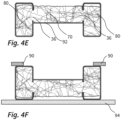
- the Figure 4E Concrete is poured in in the manner illustrated, which collects both in the interior of the hollow profiles 30A and in the space between the hollow profiles and hardens there, so that it then forms the internal structures 80 and the connecting structure 70. Due to the recesses 36, it is sufficient to add the liquid concrete from the intermediate area. It then runs through the recess 36 into the hollow profiles 30A. Due to the reversed orientation at this time, it is guaranteed that the concrete reaches the walls of the hollow profiles 30A, which are pointing downwards at this time, and at least largely covers them completely. It is also guaranteed that the concrete forms a largely flat surface in the area of the cover 92. Opposite this, in the case of the orientation in Figure 4E thus at the top, a rough surface forms, but this does not represent any disadvantages in practice during operation.
- At least one base plate 94 is attached to the main supports 20. Opposite this, the guide rails 90 are attached, in particular screwed on.
- FIG. 5 shows an alternative construction.
- tension rods 42 are provided on the outer wall 32B of the longitudinal sides 32D of the hollow profiles, which extend into the concrete connecting structure 70 and thus also allow the transmission of tensile forces between the main beams 20 via the connecting structure 70.
- no additional connecting elements 40 according to the Figures 2 to 4F are shown, these connecting elements can also be provided here, so that the tie rods 42 merely represent an additional measure.
- the connecting elements 40 are dispensed with, so that the main supports 20 are only connected via the connecting structure 70 and, if applicable, via the Figure 5 base plates 94, not shown, are connected to each other.
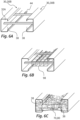
- the Figures 6A to 6C illustrate another possible design of the robot travel axis 10.
- the profiles 30 are not designed as hollow profiles 30A, but as C-profiles 30B.
- the walls of these C-profiles 30B facing each other have slot-like profile interruptions 38.
- the connecting elements 40 which in this case are also preferably formed by metal rods or metal hollow profiles, extend in this design into the profiles 30 and are attached, in particular welded, to the inner wall 32A of the walls of the profiles 30 facing away from one another.
- the design elements Figures 6A to 6C a metallic reinforcement structure 98, which is placed before the concrete is placed in order to give the concrete greater stability. Deviating from the Figure 6B it can be provided that this reinforcement structure is wider so that it extends into the inner area of the C-profiles 30B
- a concrete structure is also provided here, which is formed by internal structures within the C-profiles 30B and a connecting structure 70. This can be cast in one go due to the profile openings 38.
Landscapes
- Engineering & Computer Science (AREA)
- Robotics (AREA)
- Mechanical Engineering (AREA)
- On-Site Construction Work That Accompanies The Preparation And Application Of Concrete (AREA)
- Manipulator (AREA)
- Bridges Or Land Bridges (AREA)
Description
- Die Erfindung betrifft eine Roboter-Fahrachse zur translativen Verlagerung eines Roboterschlittens sowie ein Robotersystem mit einer solchen Roboter-Fahrachse und einem entlang der Roboter-Fahrachse verfahrbaren Roboterschlitten, mittels dessen ein Roboter in einer Fahrrichtung verfahrbar ist. Die Erfindung betrifft darüber hinaus ein neuartiges Herstellungsverfahren zur Herstellung einer Roboter-Fahrachse.
- Gattungsbildende Roboter-Fahrachsen sind aus dem Stand der Technik allgemein bekannt. Sie dienen der Bewegung eines herkömmlichen Industrieroboters entlang eines definierten und üblicherweise geradlinigen Bewegungspfades. Den Bedarf hierfür gibt es in vielen industriellen Anwendungsfeldern, beispielsweise in der Fertigung, wenn der Roboter an verschiedenen Stellen eingesetzt werden soll, oder in Fällen, in denen der Roboter bestimmungsgemäß ein Werkstücklager anfahren können soll, um dort Teile zu ergreifen. Insbesondere beim Bau von Personenkraftwagen finden gattungsgemäße Roboter-Fahrachsen Verwendung. Sie werden hier an verschiedenen Bearbeitungspositionen eingesetzt, um einen Roboterschlitten mit dem darauf angebrachten Roboter zwischen Fahrzeugheck und Fahrzeugfront verfahren zu können. Gattungsgemäße Roboter-Fahrachsen sind üblicherweise einige Meter lang, insbesondere etwa 3 m, 6 m oder 12 m. Aber auch längere Fachachsen mit bis zu 100m sind möglich. Im Falle langer Fahrwegekann dies auch mittels mehrerer gekoppelter Roboter-Fahrachsen erzielt werden.
- Bekannte Roboter-Fahrachsen sind meist als vollständig metallische Fahrachsen ausgebildet, die meist überwiegend aus Komponenten aus Aluminium oder Stahl bestehen. Dies führt zu einem vergleichsweise hohen Preis der Fahrachsen.
- Aus der
EP 3 378 605 A1 und derEP 3 441 523 A1 sind bereits Gestaltungen von Roboter-Fahrachsen bekannt, bei denen Beton einen wesentlichen Teil von Roboter-Fahrachsen bildet. Die dort beschriebenen Gestaltungen sind daher in Hinblick auf die Materialkosten von Vorteil. Auch sind die Dämpfungseigenschaften der in den Dokumenten beschriebenen Fahrachsen sehr gut. In der Praxis hat sich jedoch herausgestellt, dass die Herstellung solcher Fahrachsen recht aufwändig ist, so dass der Vorteil der Materialkosten in der Praxis die Gesamtkosten für die Herstellung gegenüber klassischen Fahrachsen aus Stahl oder Aluminium kaum senkt. - Aufgabe der Erfindung ist es, eine Fahrachse zur Verfügung zu stellen, welche hohen Qualitätsanforderungen genügt und günstig in hohen Stückzahlen hergestellt werden kann.
- Zur Lösung dieser Aufgabe wird eine Roboter-Fahrachse vorgeschlagen, die über zwei parallel verlaufende Hauptträger verfügt, die jeweils außenseitig durch ein metallisches Profil in Form eines Hohlprofils oder C-Profils begrenzt werden. Sind die vorzugsweise als Rechteckprofile ausgebildeten Profile als Hohlprofile ausgestaltet, so sind sie zumindest in Teilabschnitten umfänglich geschlossen, wobei sie in der im weiteren noch beschriebenen Weise vorzugsweise Aussparungen in Form von Durchbrechungen aufweisen. Sind die Rechteckprofile als C-Profile ausgestaltet, so weisen sie mindestens drei vorzugsweise im rechten Winkel zueinander stehende Wandungen auf, die einen Innenraum umgeben, während sie auf einer Seite offen sind, entweder indem an der offenen Seite keinerlei Wandung vorgesehen ist oder indem die vierte Wandung zwar vorhanden ist, durch eine Profilunterbrechung des Querschnitts jedoch unterbrochen ist, so dass sich in Längsrichtung des Profils eine Art Schlitz erstreckt.
- Diese Hauptträger, deren Außenform durch die genannten Profile definiert ist, tragen jeweils eine Führungsschiene, die insbesondere mittels einer Schraubverbindung an den Profilen angebracht ist. Alternative Fügetechniken zur Anbringung der Führungsschienen an den Profilen umfassen Schweißen, Nieten oder je nach Anwendungsfall auch Kleben. Auf den Führungsschienen liegt im Betrieb der Roboterschlitten auf, der insbesondere auf Fahrrollen in Haupterstreckungsrichtung der Fahrachse verfahrbar ist. Die Hauptträger sind mit einer Verbindungsstruktur aus Beton oder aus einem Polymermaterial, insbesondere einem ausgehärteten Strukturschaum aus Polymermaterial, oder aus Metallschaum miteinander verbunden. Diese Verbindungsstruktur ist zwischen den Hauptträgern angeordnet. Zusätzlich sind auch die Profile selbst mit einer Innenstruktur aus Beton oder aus Polymermaterial oder Metallschaum versehen.
- Eine Innenstruktur aus Beton, aus Metallschaum oder aus Polymermaterial in den Profilen und im Zwischenbereich zwischen den Hauptträgern hat sich als sehr vorteilhaft zur Reduzierung der Schallemissionen im Betrieb sowie zur Erzielung einer Dämpfung und somit zur Reduzierung von Vibrationen erwiesen. Hierdurch wird Verschleiß an den Hauptträgern und den Führungsschienen reduziert. Beton führt zusätzlich zu einer deutlich erhöhten Stabilität, da er sehr gut in Querrichtung wirkende Druckkräfte aufnehmen kann.
- Wird Beton verwendet, so bestehen die Innenstrukturen und die Verbindungsstruktur vorzugsweise aus einfachem Baubeton / Zementbeton. Auch ist es möglich, den Beton mit Fasereinlagen zu versehen, vorzugsweise mit Netzen oder Matten. Ein solcher Beton wird auch als Textilbeton bezeichnet. Zudem wird es als vorteilhaft angesehen, wenn der Beton mit Armierungen versehen ist, also mit einer eingegossenen Metallstruktur.
- Findet Polymermaterial Anwendung, so handelt es sich vorzugsweise um einen hieraus bestehenden ausgehärteten Strukturschaum, beispielsweise um Polyurethanschaum oder Polystyrol, oder um ein Hartschaumstoff.
- Findet Metallschaum Anwendung, so handelt es sich hierbei um ein Zweiphasensystem, umfassend Bläschen, die durch feste Metall-Wände getrennt sind. Hergestellt wird ein solcher Metallschaum vorzugsweise durch Schäumen von Schmelzen mit Hilfe von Treibmitteln oder mittels Gasinjektion erzeugt.
- Die Innenstruktur innerhalb der Profile führt in genannter Art insbesondere zu vorteilhaften Dämpfungseigenschaften, insbesondere bei schnellen und ruckhaften Bewegungen des Roboterschlittens oder des darauf montierten Roboters. Insbesondere bei der Verwendung von Beton kann die Innenstruktur in der Praxis weiterhin dazu führen, dass vergleichsweise dünnwandige Profile verwendet werden können. Neben den technischen Vorteilen ist eine erfindungsgemäße Fahrschiene wirtschaftlich vorteilhaft. Aufgrund einfacher Herstellbarkeit und geringer Materialkosten ist sie sowohl klassischen Fahrschienen aus Metall als auch den eingangs genannten Fahrschienen aus Beton und Metall überlegen.
- Insbesondere liegt die mittlere Wandungsstärke der Profile unterhalb von 8 mm, vorzugweise bei maximal 6 mm. Derart geringe Wandungsstärken können bei Verwendung einer erfindungsgemäßen Roboter-Fahrachse genutzt werden, selbst wenn auf dieser ein Roboterschlitten mit aufgesetztem Roboter mit einer Gesamtmasse von mehr als 1000 kg oder auch mehr als 1500 kg ruht. Vorzugsweise beträgt diese Gesamtmasse von Roboterschlitten und Roboter bei Verwendung von Wandungsstärken unterhalb von 8 mm jedoch vorzugsweise nicht mehr als 3000 kg, im Falle von Wandungsstärken unterhalb von 6 mm vorzugsweise nicht mehr als 2500 kg.
- Auch können bei einer erfindungsgemäßen Gestaltung die Profile einen vergleichsweise kleinen Querschnitt aufweisen. Bezogen auf die oben genannte bevorzugte Masse des Roboterschlittens mit Roboter beträgt die Breite der Profile in Querrichtung vorzugsweise 180 mm oder weniger. Die Innenstruktur aus Beton, aus Polymermaterial oder aus Metallschaum muss die jeweiligen Profile nicht vollständig ausfüllen. Es wird jedoch angestrebt, dass zumindest die nach im Betrieb oben weisende Wandung der Profile innenseitig vollständig mit der Innenstruktur in Kontakt ist. In Hinblick auf die gegenüberliegende und im Betrieb untere Wandung des Profils ist dies jedoch nicht erforderlich, was das Gießen des Betons, des Polymermaterials oder des Metallschaums während der Herstellung vereinfachen kann.
- Die Verbindungsstruktur zwischen den Hauptträgern dient vor allem der Übertragung von Drucckräften zwischen den Hauptträgern. Dies gilt insbesondere für die Verwendung von Beton und von Metallschaum. Jedoch kann auch geeignetes Polymermaterial zur Kraftübertragung beitragen. Die Verbindungsstruktur steht mit beiden Profilen der Hauptträger in Kontakt.
- Bezogen auf die Haupterstreckungsrichtung der Fahrachse ist vorzugsweise vorgesehen, dass sowohl die Innenstruktur in den Profilen als auch die Verbindungsstruktur sich zumindest annähernd (>80%) über die Gesamtlänge der Profile erstreckt. Vorzugsweise bildet eine Oberseite der Verbindungsstruktur eine durchgehende, nach oben weisende Betonfläche, Metallschaumfläche oder Polymerfläche von einem Ende der Fahrachse bis zum gegenüberliegenden anderen Ende.
- Eine erfindungsgemäße Fahrachse weist üblicherweise eine Länge von 3 m, 6 m oder 12 m auf. Werden größere Längen benötigt, so können eine Mehrzahl von Fahrachsen hintereinander montiert werden.
- Vorzugsweise bilden die Verbindungsstruktur und die Innenstrukturen eine zusammenhängende Betonstruktur, Metallschaumstruktur oder Polymermaterialstruktur. Zur Erzielung dessen kann insbesondere vorgesehen sein, dass die Profile als Hohlprofile ausgebildet sind und an einer Längsseite über die bereits genannte mindestens eine Aussparung verfügen, durch die die Betonstruktur, die Metallschaumstruktur oder Polymermaterialstruktur hindurchragt. Vorzugsweise sind mehrere Aussparungen vorgesehen, wobei die lichte Querschnittsfläche der einzelnen Aussparungen vorzugsweise jeweils mindestens 15 cm2 beträgt. Wenn die Profile als C-Profile ausgebildet sind, verfügen sie aufeinander zu weisend jeweils über eine sich in Haupterstreckungsrichtung der Profile erstreckende Profilunterbrechung, durch die die Betonstruktur, die Metallschaumstruktur oder die Polymermaterialstruktur vorzugsweise hindurchragt. Die Breite der Profilunterbrechung beträgt vorzugsweise mindestens 3 cm. Im Falle einer Gestaltung der Profile als C-Profile wird es als vorteilhaft angesehen, wenn die mit der Profildurchbrechung ausgestaltete Wandung des Profils einseitig oder beidseitig über Wandungsabschnitte verfügt, die sich in Richtung der Profildurchbrechung und im Falle zweier Wandungsabschnitte aufeinander zu erstrecken, und dass diese Wandungsabschnitte von der genannten Betonstruktur, der Metallschaumstruktur oder der Polymermaterialstrukturbeidseitig eingefasst sind. Hierdurch wird eine sehr feste Verbindung zwischen der Betonstruktur, der Metallschaumsatruktur bzw. Polymermaterialstruktur und den C-Profilen erreicht.
- Die mindestens eine Aussparung je Profil, vorzugsweise in Form einer Durchbrechung, bzw. die Profilunterbrechungen an den Profilen sind in Richtung des Zwischenraums zwischen den Profilen ausgerichtet und verbinden somit den jeweiligen Profilinnenraum mit dem Zwischenraum. Dies erleichtert das Einbringen des Betons, des Metallschaums oder des Polymermaterials, da in einem gemeinsamen Gießvorgang und vorzugsweise vom Zwischenraum aus allen genannten Räumen mit Beton, Metallschaum oder Polymermaterial ausgegossen werden können.
- Zudem hilft die sich einstellende Einheitlichkeit der Struktur, insbesondere der Betonstruktur, umfassend sowohl die Innenstrukturen als auch die Zwischenstruktur bei der Übertragung von Drucckräften zwischen den äußeren Wandungen der jeweiligen Profile und verbessert so sowohl die Dämpfung als auch die Festigkeit der Fahrachse.
- Die Hauptträger sind jedoch vorzugsweise nicht ausschließlich über die Verbindungsstruktur verbunden.
- Stattdessen ist vorzugsweise vorgesehen, dass die Hauptträger miteinander über metallische Verbindungselemente verbunden sind, wobei insbesondere vorzugsweise eine Mehrzahl dieser Verbindungselemente die Hauptträger leiterartig miteinander verbindet. Die Verbindungselemente sind vorzugsweise als metallische Hohlprofile oder als Metallbleche vorgesehen, deren Erstreckungsrichtung mit der Haupterstreckungsrichtung der Hauptträger einen Winkel von 90° einschließen. Die Stirnenden der Verbindungselemente sind an den beiden Profilen befestigt, insbesondere per Schraub- oder Schweißverbindung.
- Die Verbindungselemente sind vorzugsweise bis auf ihre jeweiligen Stirnenden vollständig vom Beton der Verbindungsstruktur und gegebenenfalls auch der Innenstruktur umgeben. Hierdurch wird die Stabilität der Fahrachse positiv beeinflusst. Es sind jedoch auch Gestaltungen denkbar, bei denen die Verbindungselemente sich nur teilweise mit Ihrer Außenseite in Kontakt mit der Betonstruktur oder der Polymermaterialstruktur befinden oder vollständig frei von Kontakt mit der Betonstruktur oder Polymermaterialstruktur sind.
- Im Falle der Verwendung von Hohlprofilen ist vorzugsweise vorgesehen, dass die metallischen Verbindungselemente an einer Außenseite von aufeinander zueinander weisenden Wandungen der
- Profile befestigt ist. Die in dieser Wandung vorzugsweise vorgesehenen Aussparungen, durch die hindurch die Betonstruktur, die Metallschaumstruktur oder Polymermaterialstruktur ragt, sind bezogen auf die Haupterstreckungsrichtung vorzugsweise zwischen zwei metallischen Verbindungselemente angeordnet.
- Im Falle der Verwendung von C-Profilen ist vorzugsweise vorgesehen, dass die metallischen Verbindungselemente an einer Innenseite von voneinander weg weisenden Wandungen der C-Profile befestigt sind, so dass sie sich durch einen Innenraum der Profile, durch die Profilunterbrechung des C-Profils sowie durch den Zwischenraum hindurch erstrecken.
- Alternativ oder zusätzlich zu den genannten Verbindungselementen, die sich insbesondere vorzugsweise in Kontakt mit der Innenstruktur und/oder der Verbindungsstruktur befinden, kann bei einer Roboter-Fahrachse auch vorgesehen sein, dass die Hauptträger mit mindestens einer Standplatte versehen sind. Die Standplatte selbst steht vorzugsweise nicht in Kontakt mit der Betonstruktur, der Metallschaumstruktur oder der Polymermaterialstruktur und wird insbesondere vorzugsweise auch erst nach dem Eingießen und Aushärten des Betons, des Metallschaums oder Polymermaterials angebracht.
- Es handelt sich vorzugsweise um mindestens eine Standplatte, die an einer Unterseite der Profile vorgesehen ist und mit diesen durch eine Schraub- oder Schweißverbindung verbunden ist. Die Roboter-Fahrachse kann eine einzige Standplatte aufweisen, die sich zumindest annähernd über die Gesamtlänge der Fahrachse erstreckt. Es können jedoch auch eine Mehrzahl von Standplatten vorgesehen sein, die an den jeweils beiden Hauptträgern schwellenartig befestigt sind oder die jeweils nur an einem der Hauptträger befestigt sind.
- Die mindestens eine Standplatte bildet üblicherweise die Bodenplatte, die direkt auf einem Hallenboden aufgestellt und an diesem verankert wird. Die Standplatte kann jedoch aufgrund von zusätzlichen Zwischenelementen wie Stellfüßen oder bei Verwendung auf einem Portal auch von einem Hallenboden beabstandet angeordnet und mittelbar mit dem Hallenboden verbunden sein. Zur Befestigung auf einem Hallenboden oder an einem Zwischenelement der genannten Art weist die Standplatte vorzugsweise Löcher auf, durch die hindurch beispielsweise Schrauben zur Fixierung der Fahrachse am Hallenboden oder einem Zwischenelement festgeschraubt werden können.
- Insbesondere zusätzlich zu der mindestens einen genannten Standplatte und zu dem mindestens einen genannten Verbindungselement, jedoch auch bei einer Gestaltung ohne Standplatte und ohne Verbindungselemente, können an den Hauptträgern Zuganker vorgesehen sein, die sich in die Innenstruktur oder die Verbindungsstruktur erstrecken und somit eine festere Verbindung zwischen den Hauptträgern und dem Beton, dem Metallschaum bzw. dem Polymermaterial ermöglichen. Solche Zuganker weisen eine Aufweitung auf, die nach Eingießen bzw. Einbringen in Beton, in den Metallschaum oder in die Polymasse bzw. den Polymerschaum eine formschlüssige Sicherung bildet. Insbesondere können die genannten Zuganker an den zueinander gerichteten Wandungen der Profile vorgesehen sein und sich in den Zwischenraum erstrecken, um dort in die Verbindungsstruktur aus Beton, aus Metallschaum oder Polymermaterial eingebettet zu werden. Es ist allerdings auch möglich, Zuganker an der Innenseite der Wandungen des Profils vorzusehen und hierdurch die Verbindung zwischen den Profilen und der Innenstruktur zu verbessern. Die Zuganker sind vorzugsweise an den Profilen angeschweißt oder angeschraubt.
- Eine alternative Möglichkeit, die Verbindung zwischen dem Beton, dem Metallschaum und der Polymermaterial herzustellen oder zu verbessern, besteht darin, dass zwischen einer Innenwand der Profile und der Innenstruktur und/oder zwischen einer Außenwand der Profile oder dem metallischen Verbindungselement und der Verbindungsstruktur eine Schicht aus einem Haftvermittlungsmittel vorgesehen ist. Insbesondere bei Verwendung von Beton ist dies von Vorteil und begünstigt die Übertragbarkeit von Zugkräften zwischen dem Beton und den Profilen.
- Ein solches Haftvermittlungsmittel kann insbesondere eine raue Oberflächenstruktur an den Profilen oder den Verbindungselementen zur Verfügung stellen, mit der der Beton oder gegebenenfalls auch das Polymermaterial eine formschlüssige Verbindung eingeht. Vorzugsweise umfasst das Haftvermittlungsmittel eine während der Herstellung flüssige Klebermasse sowie ein damit an den metallischen Oberflächen fixiertes feinkörniges Granulat, vorzugsweise mit einer mittleren Korngröße zwischen 1 mm und 5 mm. Die Klebermasse, die nach Aufbringung auf der Oberfläche und Einbringung des Granulats verfestigt, wird vorzugsweise durch ein Harz gebildet, insbesondere durch Epoxidharz. Das Granulat wird vorzugsweise durch scharfkantigen Korundgranulat gebildet.
- Von besonderem Vorteil ist es, wenn mindestens eine im Betrieb nach oben weisender Wandung, auf deren Oberseite die Führungsschiene befestigt ist, nach innen weisend das beschriebene Haftvermittlungsmittel aufweist. Ein inniger Halt zwischen dieser Profilwandung und der Innenstruktur ist für die Erzielung der gewünschten Dämpfung von großem Wert.
- Die Erfindung betrifft neben der Roboter-Fahrachse als solcher auch ein Robotersystem mit einer Fahrachse der beschriebenen Art. Zusätzlich weist das Robotersystem einen entlang der Fahrachse verlagerbaren Roboterschlitten auf, auf dem ein Roboter fest montiert oder montierbar ist.
- Der Roboterschlitten weist Rollen auf, mittels derer er auf den Führungsschienen der Fahrachse verfahren werden kann. Er kann zu diesem Zweck extern angetrieben sein, beispielsweise mit einem Seilzugsystem. Üblich ist jedoch, dass der Roboterschlitten selbst über einen mitfahrenden Antriebsmotor verfügt.
- Zur Versorgung des Roboterschlittens und des Roboters mit Elektrizität und gegebenenfalls auch mit Verbrauchsmaterialen wie Lack sind vorzugsweise Leitungen vorgesehen, die mindestens ein Leitungsbündel bilden, welches im einem Ablageraum zwischen den Führungsschienen angeordnet ist.
- Die Erfindung betrifft weiterhin ein Verfahren zur Herstellung einer Roboter-Fahrachse der beschriebenen Art und darauf aufbauend zur Herstellung eines Robotersystems der beschriebenen Art.
- Zur Herstellung der Roboter-Fahrachse werden die beiden Profile in paralleler Ausrichtung positioniert und in dieser Ausrichtung fixiert. Vorzugsweise sind die Profile zu diesem Zeitpunkt bereits über angeschweißte oder angeschraubte Verbindungselementen miteinander verbunden, welche eine korrekte Relativanordnung der Profile gewährleistet. Die Profile werden vorzugsweise in einer gegenüber der späteren Nutzausrichtung umgedrehten Ausrichtung fixiert, so dass die spätere Oberseite nach unten weist.
- Anschließend wird in die Profile sowie in einen Zwischenraum zwischen den Profilen Beton, Metallschaum oder Polymermaterial eingebracht oder die Profile und der Zwischenmaterial werden hiermit ausgeschäumt. Der aushärtete Beton bzw. das ausgehärtete Polymermaterial bzw. der ausgehärtete Metallschaum bildet dadurch die beschriebene Innenstruktur und die beschriebene Verbindungsstruktur. Durch die bevorzugte umgedrehte Ausrichtung wird erreicht, dass die Innenstruktur selbst dann, wenn die Profile nicht vollständig durch sie ausgefüllt sind, mindestens an einer im Betrieb nach oben weisenden Wandung flächig anliegt.
- Das Einbringen oder Eingießen des Betons, des Metallschaums oder es Polymermaterials zur Herstellung der Innenstrukturen und der Verbindungsstruktur kann isoliert voneinander und gegebenenfalls auch nacheinander erfolgen, so dass die beiden Innenräume und der Zwischenraum nicht in einem Zug ausgegossen werden. Von Vorteil ist es allerdings, wenn weitgehend gleichzeitig der Beton, der Metallschaum oder das Polymermaterial sowohl in die Innenräume als auch in den Zwischenraum eingebracht wird, vorzugsweise indem nur an einer Stelle der flüssige Beton, der Metallschaum oder das flüssige Polymermaterial zugeführt wird und sich von hier aus im Zwischenraum und den Innenräumen der Profile verteilt.
- Dies kann insbesondere dadurch erreicht werden, dass die verschiedenen Räume durch die beschriebenen Aussparungen oder Profilunterbrechungen miteinander verbunden sind.
- Vorzugsweise wird die Haftkraft zwischen dem Beton, dem Metallschaum oder dem Polymermaterial und den Oberflächen der Profile und/oder der Verbindungselemente verbessert, indem vor dem Einbringen des Betons, des Metallschaums oder des Polymermaterials ein Haftvermittlungsmittel auf den genannten Oberflächen aufgebracht wird, so dass diese zumindest teilweise mit dem Haftvermittlungsmittel bedeckt sind, wenn der Beton, der Metallschaum oder das Polymermaterial eingebracht wird. Welche Schritte zur Verbesserung der Haftung zweckmäßig sind, hängt vor allem auch davon ab, ob Beton, Polymermaterial oder Metallschaum die Innenstruktur bildet. Bei Polymermaterial werden insbesondere durch chemische Aktivierung der Oberflächen und/oder Plasmabehandlung gute Ergebnisse erzielt.
- Das Haftvermittlungsmittel wird vorzugsweise in einem zweistufigen Verfahren aufgebracht, bei dem zunächst eine flüssige Klebermasse auf den Oberflächen aufgebracht wird. Dies kann im Falle der Innenräume der Profile insbesondere durch Einführen einer Sprühlanze erfolgen, die durch die offenen Stirnenden der Profile oder seitlich durch die genannten Aussparungen oder Profilunterbrechungen in die Profile einfährt und dort durch Sprühen oder durch Abgabe eines Nebels die Klebermasse einbringt, die sich dann an den Oberflächen niederschlägt. Insbesondere kann es sich um ein Epoxidharz oder ein anderweitiges Harz handeln, ggf. mit weiteren Zusätzen oder Bestandteilen. Gleichzeitig oder vorzugsweise in einem späteren Verfahrensschritt wird ein feinkörniges Granulat eingebracht, vorzugsweise mit einer mittleren Korngröße zwischen 1 mm und 5 mm. Die Körner dieses Granulats gelangen auf den Film der Klebermasse, welcher sie fixiert. Sobald die Klebermasse ausreichend verfestigt und das Granulat daher ausreichend an den metallischen Oberflächen fixiert ist, kann das Gießen des Betons oder des Polymermaterials oder das Einbringen des Metallschaums folgen.
- Der Verbund aus den beiden Hauptträgern und der durch das Eingießen des Betons, des Metallschaums oder des Polymermaterials gebildeten Struktur bildet den Hauptkörper einer Fahrachse. Hieran werden bei der Herstellung nachfolgend noch die eigentlichen Führungsschienen für den Roboterschlitten angebracht und gegebenenfalls nach Anbringung geschliffen, um Maßgenauigkeit und Parallelität zu gewährleisten. Weiterhin wird an der Unterseite mindestens eine Standplatte angebracht, die der Festlegung der Führungsschiene auf einem Untergrund wie einem Hallenboden dient.
- Zur Vervollständigung des Robotersystems werden eine oder mehrere solcher Fahrachsen mit einem Roboterschlitten versehen, der den eigentlichen Roboter trägt.
- Weitere Vorteile und Aspekte der Erfindung ergeben sich aus den Ansprüchen und aus der nachfolgenden Beschreibung von bevorzugten Ausführungsbeispielen der Erfindung, die nachfolgend anhand der Figuren erläutert sind.
-
Fig. 1 zeigt ein Robotersystem der beschriebenen Art mit einer Fahrachse, einem Roboterschlitten und einem hierauf befestigten Industrieroboter. -
Fig. 2 zeigt den Hauptkörper der Fahrachse, bestehend primär aus zwei Hohlprofilen sowie einer Betonstruktur innerhalb der Profile und zwischen den Profilen. -
Fig. 3 zeigt eine Metallstruktur vor Einbringung des Betons, die die beiden Hohlprofile sowie verbindende Verbindungselemente umfasst. -
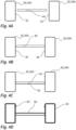
Fig. 4A bis 4F verdeutlichen exemplarisch die Herstellung einer Fahrachse der vorbeschriebenen Art. -
Fig. 5 zeigt eine Bauweise einer Fahrachse mit Zugankern. -
Fig. 6A bis 6C zeigen die Herstellung einer Fahrachse, bei der statt der genannten Hohlprofile C-Profile Verwendung finden. -
Figur 1 zeigt ein vollständiges Robotersystem 100, welches beispielsweise in der industriellen Fertigung von Kraftfahrzeugen Verwendung finden kann. Dieses Robotersystem 100 verfügt über einen Roboter 120 mit einem über mehrere Gelenke steuerbaren Roboterarm. Dieser Roboter 120 ist auf einem Roboterschlitten 110 montiert. - Der Roboterschlitten 110 ist in Verfahrrichtung 2 verfahrbar und verfügt hierfür über eine Antriebseinrichtung 112, mittels derer Rollen 114 angetrieben sind. Diese Rollen 114 ruhen auf Führungsschienen 90 einer Roboter-Fahrachse 10.
- Die Roboter-Fahrachse 10, deren Hauptkörper auch in
Figur 2 dargestellt ist, weist zwei Hauptträger 20 auf, an deren Oberseite die Führungsschienen 90 befestigt sind. Die Hauptträger 20 wiederum verfügen jeweils über ein die Außenkontur der Hauptträger 20 bildendes Profil 30, welches im Falle der Ausgestaltung derFiguren 2 bis 5 als Hohlprofil 30A ausgebildet ist. Die Hohlprofile 30A sind über metallische Verbindungselemente in Form von Querstangen, insbesondere Hohlprofilen, miteinander verbunden. Sie sind weiterhin über Standplatten 94 miteinander verbunden, die schwellenartig an der Unterseite der Hohlprofile 30A in Querrichtung ausgerichtet befestigt sind und die Befestigungslöcher 96 zum Festschrauben der Fahrachse 10 auf einem Untergrund bereitstellen. Der Innenraum der Hohlprofile 30A ist zum überwiegenden Teil durch eine Innenstruktur 80 aus Beton, insbesondere üblichem Zementbeton, gebildet. Ein Zwischenraum zwischen den Hauptträgern 20 ist zum Teil mit einer die Hauptträger 20 verbindenden Verbindungsstruktur 70 aus Beton gefüllt. - Im Rahmen des Ausführungsbeispiels werden die Innenstruktur 80 und die Verbindungsstruktur 70 als Betonstruktur beschrieben. Es kann sich jedoch gleichermaßen auch um eine Polymermaterialstruktur oder eine Struktur aus Metallschaum handeln.
-
Figur 3 zeigt die metallische Grundstruktur der Fahrachse 10, bestehend aus den beiden genannten Hohlprofilen 30A sowie den Verbindungselementen 40, welche an aufeinander zuweisenden Längsseiten 32D mittels Schweißverbindungen mit den Hohlprofilen 30A verbunden sind. Zusätzlich ist inFigur 3 zu erkennen, dass die Hohlprofile 30A über Aussparungen 36 verfügen, die jeweils den Innenraum der Hohlprofile 30A mit dem Zwischenraum zwischen den Hohlprofilen 30A verbinden. - Anhand von
Figur 4A bis 4F wird die Herstellung der Roboter-Fahrachse erläutert. Ausgehend von den bereits mit Aussparungen 36 versehenen Hohlprofilen 30A sowie den Verbindungselementen 40 wird zunächst eine einheitliche Metallstruktur geschaffen, indem die Verbindungselemente 40 an den aufeinander zuweisenden Außenwänden 32B der Hohlprofile 30A angeschweißt werden. Es ergibt sich eine etwa leiterartige Metallstruktur, die inFigur 4B dargestellt ist. - Anschließend wird diese Metallstruktur gewendet, so dass eine spätere Oberseite der Hohlprofile 30A nach unten weist. Weiterhin wird eine stabile oder formflexible Abdeckung unterhalb der Verbindungselemente 40 positioniert.
- Wie in
Figur 4D dargestellt ist, wird anschließend auf metallischen Oberflächen der Grundstruktur ein Haftvermittlungsmittel 60 flächig aufgebracht, welches insbesondere aus einem flüssigen Kleber besteht, beispielsweise Epoxidharz, welcher beispielsweise über Sprühdüsen, insbesondere am Ende von Einführlanzen, auf den verschiedenen Oberflächen der Metallstruktur aufgebracht wird. Anschließend wird ein Korundgranulat, welches in den Darstellungen nicht dargestellt ist, eingebracht. Die Granulatkörner des Korundgranulat werden bei Kontakt mit den Wandungen der Metallstruktur durch den Kleber gehalten und bilden somit nach Befestigung des Klebers eine raue Oberflächenstruktur. - Anschließend wird in der
Figur 4E verdeutlichten Weise Beton eingegossen, der sich sowohl in den Innenräumen der Hohlprofile 30A als auch in dem Zwischenraum zwischen den Hohlprofilen sammelt und dort aushärtet, so dass er dann die Innenstrukturen 80 und die Verbindungsstruktur 70 bildet. Aufgrund der Aussparungen 36 reicht es aus, den flüssigen Beton vom Zwischenbereich aus zuzugeben. Durch die Aussparung 36 hindurch läuft dieser dann in die Hohlprofile 30A. Aufgrund der umgedrehten Ausrichtung zu diesem Zeitpunkt ist dabei gewährleitet, dass der Beton die zu diesem Zeitpunkt nach unten weisenden Wandungen der Hohlprofile 30A erreicht und diese zumindest weitgehend vollständig bedeckt. Auch ist gewährleitet, dass der Beton im Bereich der Abdeckung 92 eine weitgehend plane Oberfläche bildet. Gegenüberliegend hierzu, im Falle der Ausrichtung der Figur 4E somit oben, bildet sich eine raue Oberfläche, was jedoch in der Praxis im Betrieb keine Nachteile darstellt. - Abschließend wird in der aus
Figur 4F ersichtlichen Weise die mindestens eine Standplatte 94 an den Hauptträgern 20 angebracht. Gegenüberliegend hierzu werden die Führungsschienen 90 angebracht, insbesondere angeschraubt. - Die
Figur 5 zeigt eine alternative Bauweise. Bei dieser ist vorgesehen, dass an der Außenwand 32B der Längsseiten 32D der Hohlprofile Zuganker 42 vorgesehen sind, die sich in die Verbindungsstruktur 70 aus Beton erstrecken und somit auch die Übertragung von Zugkräften zwischen den Hauptträgern 20 über die Verbindungsstruktur 70 gestatten. Obwohl inFigur 5 keine darüberhinausgehenden Verbindungselemente 40 entsprechend denFiguren 2 bis 4F dargestellt sind, können diese Verbindungselemente hier ebenfalls vorgesehen sein, so dass die Zuganker 42 lediglich eine zusätzliche Maßnahme darstellen. Es sind jedoch auch Gestaltungen denkbar, bei denen auf die Verbindungselemente 40 verzichtet wird, so dass die Hauptträger 20 lediglich über die Verbindungsstruktur 70 sowie ggf. über die inFigur 5 nicht dargestellten Standplatten 94 miteinander verbunden sind. - Die
Figuren 6A bis 6C verdeutlichen eine weitere mögliche Bauweise der Roboter- Fahrachse 10. Hier sind die Profile 30 nicht als Hohlprofile 30A, sondern als C-Profile 30B ausgebildet. Die aufeinander zugerichteten Wandungen dieser C-Profile 30B weisen schlitzartige Profilunterbrechungen 38 auf. Die Verbindungselemente 40, die auch in diesem Fall vorzugsweise durch Metallstangen oder Metallhohlprofile gebildet sind, erstrecken sich bei dieser Gestaltung bis in die Profile 30 hinein und sind an der Innenwand 32A der voneinander wegweisenden Wandungen der Profile 30 befestigt, insbesondere angeschweißt. Zusätzlich weisen die gestaltendenFiguren 6A bis 6C eine metallische Armierungsstruktur 98 auf, die vor Einfügen des Betons platziert wird, um dem Beton größere Stabilität zu verleihen. Abweichend von derFigur 6B kann vorgesehen sein, dass diese Armierungsstruktur breiter ausgebildet ist, so dass sie sich bis in den Innenbereich der C-Profile 30B erstreckt - Wie anhand von
Figur 6C zu erkennen ist, ist auch hier eine Betonstruktur vorgesehen, die durch Innenstrukturen innerhalb der C-Profile 30B und einer Verbindungsstruktur 70 gebildet wird. Diese kann aufgrund der Profildurchbrechungen 38 in einem Zug gegossen werden.
Claims (15)
- Roboter-Fahrachse (10) zur translativen Verlagerung eines Roboterschlittens (110) mit den folgenden Merkmalen:a. die Roboter-Fahrachse (10) verfügt über zwei parallel verlaufende Hauptträger (20), die jeweils außenseitig durch ein metallisches Profil (30) in Form eines Hohlprofils (30A) oder C-Profils (30B) begrenzt werden, undb. die Hauptträger (20) tragen jeweils eine Führungsschiene (90),gekennzeichnet durch die folgenden weiteren Merkmale:c. die Hauptträger (20) sind mit einer Verbindungsstruktur (70) aus Beton miteinander verbunden, undd. die Profile (30) der Hauptträger (20) weisen eine Innenstruktur (80) auf, die- aus Beton, oder- aus einem Polymermaterial, insbesondere aus Polymer-Strukturschaum, oder- aus Metallschaumgebildet ist.
- Roboter-Fahrachse (10) nach Anspruch 1 mit den folgenden weiteren Merkmalen:a. die Profile (30) sind Hohlprofile (30A) und verfügen an einer Längsseite (32D) über mindestens eine Aussparung (36), undb. die Verbindungsstruktur (70) und die Innenstrukturen (80) bilden eine zusammenhängende und durch die Aussparungen (36) hindurchragende Betonstruktur (70, 80) oder Polymermaterialstruktur (70, 80) oder Metallschaumstruktur (70, 80).
- Roboter-Fahrachse (10) nach Anspruch 1 mit den folgenden weiteren Merkmalen:a. die Profile (30) sind C-Profile (30B) und verfügen aufeinander zu weisend über eine sich in Haupterstreckungsrichtung der Profile erstreckende Profilunterbrechung (38), undb. die Verbindungsstruktur (70) und die Innenstrukturen (80) bilden eine zusammenhängende und durch die Profilunterbrechung (38) hindurchragende Betonstruktur (70, 80) oder Polymermaterialstruktur (70, 80) oder Metallschaumstruktur (70, 80).
- Roboter-Fahrachse (10) nach einem der vorstehenden Ansprüche mit dem folgenden weiteren Merkmal:a. die Hauptträger (20) sind mit mindestens einem metallischen Verbindungselement (40, 44) miteinander verbunden,insbesondere mit mindestens einem der folgenden zusätzlichen Merkmale:b. mindestens ein metallisches Verbindungselement (40, 44) wird von der Verbindungstruktur (70) umgeben, und/oderc. mindestens ein metallisches Verbindungselement (40) ist an einer Außenseite von aufeinander zueinander weisenden Wandungen der Profile (30) befestigt, vorzugsweise mittels einer Schweißverbindung, oderd. mindestens ein metallisches Verbindungselement ist an einer Innenseite von voneinander weg weisenden Wandungen der Profile befestigt, vorzugsweise mittels einer Schweißverbindung, und erstreckt sich durch die Aussparung (36) oder die Profilunterbrechung (38).
- Roboter-Fahrachse (10) nach einem der vorstehenden Ansprüche mit dem folgenden weiteren Merkmal:a. die Hauptträger (20) sind mit mindestens einer Standplatte versehen,insbesondere mit dem folgenden zusätzlichen Merkmal:
b. es ist mindestens einer Standplatte (94) vorgesehen, die die Hauptträger (20) miteinander verbindet, insbesondere mittels einer Schweiß- oder Schraubverbindung. - Roboter-Fahrachse (10) nach einem der vorstehenden Ansprüche mit den folgenden weiteren Merkmalen:
a. an den Hauptträgern (20) sind Zuganker (42) vorgesehen, die sich in die Verbindungsstruktur (70) aus Beton oder aus Polymermaterial oder aus Metallschaum erstrecken. - Roboter-Fahrachse (10) nach einem der vorstehenden Ansprüche mit mindestens einem der folgenden weiteren Merkmale:a. zwischen einer Innenwand (32A) der Profile (30) und der Innenstruktur (80) aus Beton oder aus Polymermaterial oder aus Metallschaum ist eine Schicht aus einem Haftvermittlungsmittel (60) vorgesehen, und/oderb. zwischen einer Außenwand (32B) der Profile (30) oder dem metallischen Verbindungselement (40, 44) und der Verbindungsstruktur (70) aus Beton oder aus Polymermaterial oder aus Metallschaum ist eine Schicht aus einem Haftvermittlungsmittel (60) vorgesehen, insbesondere vorzugsweise mit dem folgenden zusätzlichen Merkmal:c. das Haftvermittlungsmittel (60) umfasst eine flüssige Klebermasse sowie ein feinkörniges Granulat, insbesondere Epoxidharz und Korundgranulat.
- Roboter-Fahrachse (10) nach einem der vorstehenden Ansprüche mit mindestens einem der folgenden weiteren Merkmale:a. die Profile (30) weisen quer zur Fahrtrichtung eine Breite von weniger als 180 mm auf, und/oderb. die Profile (30) weisen eine Wandungsstärke von maximal 6 mm auf, und/oderc. die Innenstruktur (80) aus Beton oder Polymermaterial oder Metallschaum füllt einen lichten Querschnitt eines der Profile (30) nicht vollständig auf, wobei die Innenstruktur (80) jedoch mindestens an einer oberen Profilfläche (30C) des Querschnitts haftend anliegt, und/oderd. die Verbindungsstruktur (70) ist oberseitig mit einer Abdeckung (92) versehen, insbesondere in Art eines flexiblen Flächenelements.
- Robotersystem (100) mit den folgenden Merkmalen:a. das Robotersystem (100) umfasst eine Roboter-Fahrachse (10), undb. das Robotersystem (100) umfasst einen entlang der Roboter-Fahrachse (10) verfahrbaren Roboterschlitten (110), mittels dessen ein Roboter (120) in Fahrrichtung verfahrbar ist,gekennzeichnet durch das folgende zusätzliche Merkmal:
c. die Roboter-Fahrachse (10) ist nach einem der vorstehenden Ansprüche ausgebildet. - Verfahren zur Herstellung einer Roboter-Fahrachse (10) nach einem der vorstehenden Ansprüche mit den folgenden Schritten:a. die beiden Profile (30) werden in paralleler Ausrichtung positioniert, undb. in die Profile (30) sowie in einen Zwischenraum zwischen den Profilen (30) wird Beton oder ein flüssiges Polymermaterial eingegossen oder die Profile (30) sowie der Zwischenraum zwischen den Profilen (30) werden mit einem Polymermaterial oder einem Metallschaum ausgeschäumt, undc. der Beton oder das Polymermaterial oder der Metallschaum härtet aus und bildet die Innenstruktur (80) und die Verbindungsstruktur (70).
- Verfahren nach Anspruch 10 mit den folgenden weiteren Merkmalen:a. an den Längsseiten (32D) der als Hohlprofil (30A) ausgebildeten Profile (30) sind Aussparungen (36) vorgesehen, undb. beim Einbringen des Betons oder des Polymermaterials oder des Metallschaums gelangt der Beton oder das Polymermaterial durch die Aussparungen (36) in die Hohlprofile (30A) oder in den Zwischenraum.
- Verfahren nach Anspruch 10 mit den folgenden weiteren Merkmalen:a. an den Längsseiten (32D) der als C-Profil (30B) ausgebildeten Profile (30) sind Profilunterbrechungen (38) vorgesehen, undb. beim Einbringen des Betons oder des Polymermaterials oder des Metallschaums gelangt der Beton oder das Polymermaterial oder der Metallschaum durch die Profilunterbrechungen (38) in die C-Profile (30B) oder in den Zwischenraum.
- Verfahren nach einem der Ansprüche 10 bis 12 mit dem folgenden weiteren Merkmal:a. die Innenwände (32A) der Profile (30) werden vor dem Einbringen des Betons oder des Polymermaterials oder des Metallschaums zumindest teilweise mit einem Haftvermittlungsmittel (60) bedeckt,insbesondere mit mindestens einem der folgenden zusätzlichen Merkmale:b. das Haftvermittlungsmittel (60) umfasst eine flüssige Klebermasse, die insbesondere durch ein Epoxidharz oder ein anderweitiges Harz gebildet wird, und/oderc. das Haftvermittlungsmittel (60) umfasst ein feinkörniges Granulat, insbesondere Korundgranulat oder anderweitiges mineralisches Granulat, und/oderd. das Haftvermittlungsmittel (60) wird zumindest zum Teil mittels einer Lanze eingebracht, wobei die Lanze vorzugsweise durch eine der Aussparung (36) in das Hohlprofil (30A) eingebracht wird.
- Verfahren nach einem der Ansprüche 10 bis 13 mit dem folgenden weiteren Merkmal:a. zum Zwischenraum weisende Außenwände (32B) der Profile (30) und/oder mindestens ein metallisches Verbindungselement (40) werden vor dem Einbringen des Betons oder des Polymermaterials oder des Metallschaums zumindest teilweise mit einem Haftvermittlungsmittel (60) bedeckt,insbesondere mit mindestens einem der folgenden zusätzlichen Merkmale:b. das Haftvermittlungsmittel (60) umfasst eine flüssige Klebermasse, die insbesondere durch ein Epoxidharz oder ein anderweitiges Harz gebildet wird, und/oderc. das Haftvermittlungsmittel (60) umfasst ein feinkörniges Granulat, insbesondere ein Korundgranulat oder anderweitiges mineralisches Granulat.
- Verfahren nach einem der Ansprüche 10 bis 14 mit den folgenden weiteren Merkmalen:a. beim Einbringen des Betons oder des Polymermaterials oder des Metallschaums in die Profile (30) sind die Profile (30) gewendet, so dass ihre Oberseite nach unten gerichtet ist.
Priority Applications (1)
| Application Number | Priority Date | Filing Date | Title |
|---|---|---|---|
| HUE21707661A HUE070607T2 (hu) | 2021-02-22 | 2021-02-22 | Utazótengely robotok számára, robot rendszer ilyen utazótengellyel és eljárás ilyen utazótengelyek elõállítására |
Applications Claiming Priority (1)
| Application Number | Priority Date | Filing Date | Title |
|---|---|---|---|
| PCT/EP2021/054269 WO2022174926A1 (de) | 2021-02-22 | 2021-02-22 | Fahrschiene für einen roboter und robotersystem mit einer solchen fahrschiene sowie verfahren zur herstellung einer solchen fahrschiene |
Publications (2)
| Publication Number | Publication Date |
|---|---|
| EP4294604A1 EP4294604A1 (de) | 2023-12-27 |
| EP4294604B1 true EP4294604B1 (de) | 2025-01-15 |
Family
ID=74701489
Family Applications (1)
| Application Number | Title | Priority Date | Filing Date |
|---|---|---|---|
| EP21707661.1A Active EP4294604B1 (de) | 2021-02-22 | 2021-02-22 | Fahrschiene für einen roboter und robotersystem mit einer solchen fahrschiene sowie verfahren zur herstellung einer solchen fahrschiene |
Country Status (6)
| Country | Link |
|---|---|
| US (1) | US12397413B2 (de) |
| EP (1) | EP4294604B1 (de) |
| DK (1) | DK4294604T3 (de) |
| ES (1) | ES3020157T3 (de) |
| HU (1) | HUE070607T2 (de) |
| WO (1) | WO2022174926A1 (de) |
Family Cites Families (5)
| Publication number | Priority date | Publication date | Assignee | Title |
|---|---|---|---|---|
| DE3112763A1 (de) | 1981-03-31 | 1982-10-07 | Heinrich Dr.-Ing. 7000 Stuttgart Bechert | "betontraeger" |
| DE10035655C1 (de) | 2000-07-20 | 2001-09-27 | Wilhelm Tamke | Hohlprofil |
| ES2769054T3 (es) | 2017-03-23 | 2020-06-24 | Ipr Intelligente Peripherien Fuer Roboter Gmbh | Sistema de robot con raíl de soporte y plataforma de robot |
| EP3441523A1 (de) | 2017-08-11 | 2019-02-13 | IPR-Intelligente Peripherien für Roboter GmbH | Tragschiene für eine translativ verfahrbare roboterplattform |
| EP4074464A1 (de) * | 2021-03-04 | 2022-10-19 | The Boeing Company | Mechanische avatar-anordnung und system zur verwendung in einem begrenzten raum in einer struktur und verfahren zur verwendung davon |
-
2021
- 2021-02-22 EP EP21707661.1A patent/EP4294604B1/de active Active
- 2021-02-22 HU HUE21707661A patent/HUE070607T2/hu unknown
- 2021-02-22 WO PCT/EP2021/054269 patent/WO2022174926A1/de not_active Ceased
- 2021-02-22 DK DK21707661.1T patent/DK4294604T3/da active
- 2021-02-22 ES ES21707661T patent/ES3020157T3/es active Active
- 2021-02-22 US US18/547,215 patent/US12397413B2/en active Active
Also Published As
| Publication number | Publication date |
|---|---|
| HUE070607T2 (hu) | 2025-06-28 |
| WO2022174926A1 (de) | 2022-08-25 |
| DK4294604T3 (da) | 2025-03-31 |
| ES3020157T3 (en) | 2025-05-22 |
| EP4294604A1 (de) | 2023-12-27 |
| US12397413B2 (en) | 2025-08-26 |
| US20240123605A1 (en) | 2024-04-18 |
Similar Documents
| Publication | Publication Date | Title |
|---|---|---|
| DE4301763C2 (de) | Wagenkastenaufbau, insbesondere für Eisenbahnwagen zur Personenbeförderung | |
| DE2231763C2 (de) | Leitplanke | |
| EP3378605B1 (de) | Robotersystem mit tragschiene und roboterplattform | |
| EP0987370B1 (de) | Herstellungsverfahren der lagegenauen Verbindungen von Statoren an einer Magnetschwebebahn und deren Tragkonstruktion | |
| DE69613824T2 (de) | Verbindungsteile für i- oder u-träger oder träger mit anderen querprofilen | |
| WO2019030054A1 (de) | Tragschiene für eine translativ verfahrbare roboterplattform | |
| EP3441523A1 (de) | Tragschiene für eine translativ verfahrbare roboterplattform | |
| DE202017007035U1 (de) | Tragschiene für eine translativ verfahrbare Roboterplattform sowie Verfahrsystem und Robotersystem mit einer solchen Tragschiene | |
| DE3618075A1 (de) | Abstuetzung eines traegers | |
| EP4294604B1 (de) | Fahrschiene für einen roboter und robotersystem mit einer solchen fahrschiene sowie verfahren zur herstellung einer solchen fahrschiene | |
| EP0109093A1 (de) | Verstärkungsvorrichtung für Kabinen, insbesondere Aufbauten auf Lastkraftwagen | |
| DE102019112014A1 (de) | Verfahren zur Befestigung eines Brückenüberbaus und dabei zu verwendendes Randabschlusselement | |
| EP3348746B1 (de) | Fassadenplattenanordnung | |
| WO2001011143A1 (de) | Fahrweg für ein spuhrgebundenes fahrzeug, insbesondere eine magnetischwebebahn | |
| DE102017008181A1 (de) | Lärmschutzelement | |
| DE202021100859U1 (de) | Fahrschiene für einen Roboter und Robotersystem mit einer solchen Fahrschiene | |
| DE102019133999A1 (de) | Anordnung zum Verbinden eines Bauwerkteils mit einem dem Bauwerkteil vorgelagerten Außenteil | |
| DE19928757C2 (de) | Montageträgersystem und Verfahren zur Montage eines Fertigbauteils an einem Gebäudeteil | |
| EP1114221A1 (de) | Schwellenrahmen für eine gleisanlage für schienengebundene fahrzeuge, insbesondere für einen schotteroberbau | |
| WO2003016633A1 (de) | Gleisübergangseinrichtung | |
| EP3617404B1 (de) | Fahrschiene und gleiskonstruktion mit der fahrschiene | |
| WO2004033798A1 (de) | Verfahren zum herstellen einer lagegenauen verbindung an einem fahrweg | |
| DE29919191U1 (de) | Laufschienenprofil und Laufschienenanlage zur Führung von Rollenapparaten | |
| EP4361377B1 (de) | Verfahren zum errichten einer gebäudewand im 3d-druck | |
| EP3408153B1 (de) | Rohbaukasten und fahrzeug |
Legal Events
| Date | Code | Title | Description |
|---|---|---|---|
| STAA | Information on the status of an ep patent application or granted ep patent |
Free format text: STATUS: UNKNOWN |
|
| STAA | Information on the status of an ep patent application or granted ep patent |
Free format text: STATUS: THE INTERNATIONAL PUBLICATION HAS BEEN MADE |
|
| PUAI | Public reference made under article 153(3) epc to a published international application that has entered the european phase |
Free format text: ORIGINAL CODE: 0009012 |
|
| STAA | Information on the status of an ep patent application or granted ep patent |
Free format text: STATUS: REQUEST FOR EXAMINATION WAS MADE |
|
| 17P | Request for examination filed |
Effective date: 20230706 |
|
| AK | Designated contracting states |
Kind code of ref document: A1 Designated state(s): AL AT BE BG CH CY CZ DE DK EE ES FI FR GB GR HR HU IE IS IT LI LT LU LV MC MK MT NL NO PL PT RO RS SE SI SK SM TR |
|
| DAV | Request for validation of the european patent (deleted) | ||
| DAX | Request for extension of the european patent (deleted) | ||
| GRAP | Despatch of communication of intention to grant a patent |
Free format text: ORIGINAL CODE: EPIDOSNIGR1 |
|
| STAA | Information on the status of an ep patent application or granted ep patent |
Free format text: STATUS: GRANT OF PATENT IS INTENDED |
|
| INTG | Intention to grant announced |
Effective date: 20241004 |
|
| GRAS | Grant fee paid |
Free format text: ORIGINAL CODE: EPIDOSNIGR3 |
|
| GRAA | (expected) grant |
Free format text: ORIGINAL CODE: 0009210 |
|
| STAA | Information on the status of an ep patent application or granted ep patent |
Free format text: STATUS: THE PATENT HAS BEEN GRANTED |
|
| AK | Designated contracting states |
Kind code of ref document: B1 Designated state(s): AL AT BE BG CH CY CZ DE DK EE ES FI FR GB GR HR HU IE IS IT LI LT LU LV MC MK MT NL NO PL PT RO RS SE SI SK SM TR |
|
| REG | Reference to a national code |
Ref country code: CH Ref legal event code: EP Ref country code: GB Ref legal event code: FG4D Free format text: NOT ENGLISH |
|
| REG | Reference to a national code |
Ref country code: DE Ref legal event code: R096 Ref document number: 502021006431 Country of ref document: DE |
|
| REG | Reference to a national code |
Ref country code: IE Ref legal event code: FG4D Free format text: LANGUAGE OF EP DOCUMENT: GERMAN |
|
| REG | Reference to a national code |
Ref country code: DK Ref legal event code: T3 Effective date: 20250325 |
|
| REG | Reference to a national code |
Ref country code: NL Ref legal event code: FP |
|
| P01 | Opt-out of the competence of the unified patent court (upc) registered |
Free format text: CASE NUMBER: APP_17338/2025 Effective date: 20250409 |
|
| REG | Reference to a national code |
Ref country code: ES Ref legal event code: FG2A Ref document number: 3020157 Country of ref document: ES Kind code of ref document: T3 Effective date: 20250522 |
|
| REG | Reference to a national code |
Ref country code: HU Ref legal event code: AG4A Ref document number: E070607 Country of ref document: HU |
|
| PG25 | Lapsed in a contracting state [announced via postgrant information from national office to epo] |
Ref country code: RS Free format text: LAPSE BECAUSE OF FAILURE TO SUBMIT A TRANSLATION OF THE DESCRIPTION OR TO PAY THE FEE WITHIN THE PRESCRIBED TIME-LIMIT Effective date: 20250415 |
|
| PG25 | Lapsed in a contracting state [announced via postgrant information from national office to epo] |
Ref country code: FI Free format text: LAPSE BECAUSE OF FAILURE TO SUBMIT A TRANSLATION OF THE DESCRIPTION OR TO PAY THE FEE WITHIN THE PRESCRIBED TIME-LIMIT Effective date: 20250115 |
|
| PG25 | Lapsed in a contracting state [announced via postgrant information from national office to epo] |
Ref country code: PL Free format text: LAPSE BECAUSE OF FAILURE TO SUBMIT A TRANSLATION OF THE DESCRIPTION OR TO PAY THE FEE WITHIN THE PRESCRIBED TIME-LIMIT Effective date: 20250115 |
|
| PGFP | Annual fee paid to national office [announced via postgrant information from national office to epo] |
Ref country code: ES Payment date: 20250407 Year of fee payment: 5 |
|
| REG | Reference to a national code |
Ref country code: LT Ref legal event code: MG9D |
|
| PG25 | Lapsed in a contracting state [announced via postgrant information from national office to epo] |
Ref country code: IS Free format text: LAPSE BECAUSE OF FAILURE TO SUBMIT A TRANSLATION OF THE DESCRIPTION OR TO PAY THE FEE WITHIN THE PRESCRIBED TIME-LIMIT Effective date: 20250515 |
|
| PG25 | Lapsed in a contracting state [announced via postgrant information from national office to epo] |
Ref country code: HR Free format text: LAPSE BECAUSE OF FAILURE TO SUBMIT A TRANSLATION OF THE DESCRIPTION OR TO PAY THE FEE WITHIN THE PRESCRIBED TIME-LIMIT Effective date: 20250115 |
|
| PG25 | Lapsed in a contracting state [announced via postgrant information from national office to epo] |
Ref country code: LV Free format text: LAPSE BECAUSE OF FAILURE TO SUBMIT A TRANSLATION OF THE DESCRIPTION OR TO PAY THE FEE WITHIN THE PRESCRIBED TIME-LIMIT Effective date: 20250115 Ref country code: PT Free format text: LAPSE BECAUSE OF FAILURE TO SUBMIT A TRANSLATION OF THE DESCRIPTION OR TO PAY THE FEE WITHIN THE PRESCRIBED TIME-LIMIT Effective date: 20250515 |
|
| PG25 | Lapsed in a contracting state [announced via postgrant information from national office to epo] |
Ref country code: GR Free format text: LAPSE BECAUSE OF FAILURE TO SUBMIT A TRANSLATION OF THE DESCRIPTION OR TO PAY THE FEE WITHIN THE PRESCRIBED TIME-LIMIT Effective date: 20250416 Ref country code: BG Free format text: LAPSE BECAUSE OF FAILURE TO SUBMIT A TRANSLATION OF THE DESCRIPTION OR TO PAY THE FEE WITHIN THE PRESCRIBED TIME-LIMIT Effective date: 20250115 |
|
| PG25 | Lapsed in a contracting state [announced via postgrant information from national office to epo] |
Ref country code: SE Free format text: LAPSE BECAUSE OF FAILURE TO SUBMIT A TRANSLATION OF THE DESCRIPTION OR TO PAY THE FEE WITHIN THE PRESCRIBED TIME-LIMIT Effective date: 20250115 |
|
| PG25 | Lapsed in a contracting state [announced via postgrant information from national office to epo] |
Ref country code: SM Free format text: LAPSE BECAUSE OF FAILURE TO SUBMIT A TRANSLATION OF THE DESCRIPTION OR TO PAY THE FEE WITHIN THE PRESCRIBED TIME-LIMIT Effective date: 20250115 |
|
| PG25 | Lapsed in a contracting state [announced via postgrant information from national office to epo] |
Ref country code: MC Free format text: LAPSE BECAUSE OF FAILURE TO SUBMIT A TRANSLATION OF THE DESCRIPTION OR TO PAY THE FEE WITHIN THE PRESCRIBED TIME-LIMIT Effective date: 20250115 |
|
| REG | Reference to a national code |
Ref country code: DE Ref legal event code: R097 Ref document number: 502021006431 Country of ref document: DE |
|
| PG25 | Lapsed in a contracting state [announced via postgrant information from national office to epo] |
Ref country code: EE Free format text: LAPSE BECAUSE OF FAILURE TO SUBMIT A TRANSLATION OF THE DESCRIPTION OR TO PAY THE FEE WITHIN THE PRESCRIBED TIME-LIMIT Effective date: 20250115 |
|
| PG25 | Lapsed in a contracting state [announced via postgrant information from national office to epo] |
Ref country code: RO Free format text: LAPSE BECAUSE OF FAILURE TO SUBMIT A TRANSLATION OF THE DESCRIPTION OR TO PAY THE FEE WITHIN THE PRESCRIBED TIME-LIMIT Effective date: 20250115 |
|
| PG25 | Lapsed in a contracting state [announced via postgrant information from national office to epo] |
Ref country code: SK Free format text: LAPSE BECAUSE OF FAILURE TO SUBMIT A TRANSLATION OF THE DESCRIPTION OR TO PAY THE FEE WITHIN THE PRESCRIBED TIME-LIMIT Effective date: 20250115 |
|
| PLBE | No opposition filed within time limit |
Free format text: ORIGINAL CODE: 0009261 |
|
| STAA | Information on the status of an ep patent application or granted ep patent |
Free format text: STATUS: NO OPPOSITION FILED WITHIN TIME LIMIT |
|
| REG | Reference to a national code |
Ref country code: CH Ref legal event code: L10 Free format text: ST27 STATUS EVENT CODE: U-0-0-L10-L00 (AS PROVIDED BY THE NATIONAL OFFICE) Effective date: 20251126 |
|
| 26N | No opposition filed |
Effective date: 20251016 |
|
| PG25 | Lapsed in a contracting state [announced via postgrant information from national office to epo] |
Ref country code: IE Free format text: LAPSE BECAUSE OF NON-PAYMENT OF DUE FEES Effective date: 20250222 |
|
| REG | Reference to a national code |
Ref country code: CH Ref legal event code: U11 Free format text: ST27 STATUS EVENT CODE: U-0-0-U10-U11 (AS PROVIDED BY THE NATIONAL OFFICE) Effective date: 20260301 |
|
| PGFP | Annual fee paid to national office [announced via postgrant information from national office to epo] |
Ref country code: LU Payment date: 20260218 Year of fee payment: 6 Ref country code: NL Payment date: 20260218 Year of fee payment: 6 |
|
| PGFP | Annual fee paid to national office [announced via postgrant information from national office to epo] |
Ref country code: HU Payment date: 20260220 Year of fee payment: 6 |
|
| PGFP | Annual fee paid to national office [announced via postgrant information from national office to epo] |
Ref country code: GB Payment date: 20260220 Year of fee payment: 6 |
|
| PGFP | Annual fee paid to national office [announced via postgrant information from national office to epo] |
Ref country code: NO Payment date: 20260220 Year of fee payment: 6 Ref country code: DK Payment date: 20260220 Year of fee payment: 6 Ref country code: DE Payment date: 20260218 Year of fee payment: 6 |
|
| PGFP | Annual fee paid to national office [announced via postgrant information from national office to epo] |
Ref country code: AT Payment date: 20260219 Year of fee payment: 6 |
|
| PGFP | Annual fee paid to national office [announced via postgrant information from national office to epo] |
Ref country code: BE Payment date: 20260218 Year of fee payment: 6 Ref country code: IT Payment date: 20260224 Year of fee payment: 6 |
|
| PGFP | Annual fee paid to national office [announced via postgrant information from national office to epo] |
Ref country code: FR Payment date: 20260219 Year of fee payment: 6 |
|
| PGFP | Annual fee paid to national office [announced via postgrant information from national office to epo] |
Ref country code: CZ Payment date: 20260216 Year of fee payment: 6 Ref country code: CH Payment date: 20260301 Year of fee payment: 6 |