EP4295960A1 - Système de revêtement - Google Patents
Système de revêtement Download PDFInfo
- Publication number
- EP4295960A1 EP4295960A1 EP23722255.9A EP23722255A EP4295960A1 EP 4295960 A1 EP4295960 A1 EP 4295960A1 EP 23722255 A EP23722255 A EP 23722255A EP 4295960 A1 EP4295960 A1 EP 4295960A1
- Authority
- EP
- European Patent Office
- Prior art keywords
- region
- roller
- coating
- gravure
- substrate
- Prior art date
- Legal status (The legal status is an assumption and is not a legal conclusion. Google has not performed a legal analysis and makes no representation as to the accuracy of the status listed.)
- Pending
Links
Images


Classifications
-
- B—PERFORMING OPERATIONS; TRANSPORTING
- B05—SPRAYING OR ATOMISING IN GENERAL; APPLYING FLUENT MATERIALS TO SURFACES, IN GENERAL
- B05C—APPARATUS FOR APPLYING FLUENT MATERIALS TO SURFACES, IN GENERAL
- B05C9/00—Apparatus or plant for applying liquid or other fluent material to surfaces by means not covered by any preceding group, or in which the means of applying the liquid or other fluent material is not important
- B05C9/06—Apparatus or plant for applying liquid or other fluent material to surfaces by means not covered by any preceding group, or in which the means of applying the liquid or other fluent material is not important for applying two different liquids or other fluent materials, or the same liquid or other fluent material twice, to the same side of the work
-
- B—PERFORMING OPERATIONS; TRANSPORTING
- B05—SPRAYING OR ATOMISING IN GENERAL; APPLYING FLUENT MATERIALS TO SURFACES, IN GENERAL
- B05C—APPARATUS FOR APPLYING FLUENT MATERIALS TO SURFACES, IN GENERAL
- B05C1/00—Apparatus in which liquid or other fluent material is applied to the surface of the work by contact with a member carrying the liquid or other fluent material, e.g. a porous member loaded with a liquid to be applied as a coating
- B05C1/04—Apparatus in which liquid or other fluent material is applied to the surface of the work by contact with a member carrying the liquid or other fluent material, e.g. a porous member loaded with a liquid to be applied as a coating for applying liquid or other fluent material to work of indefinite length
- B05C1/08—Apparatus in which liquid or other fluent material is applied to the surface of the work by contact with a member carrying the liquid or other fluent material, e.g. a porous member loaded with a liquid to be applied as a coating for applying liquid or other fluent material to work of indefinite length using a roller or other rotating member which contacts the work along a generating line
- B05C1/0808—Details thereof, e.g. surface characteristics
-
- B—PERFORMING OPERATIONS; TRANSPORTING
- B05—SPRAYING OR ATOMISING IN GENERAL; APPLYING FLUENT MATERIALS TO SURFACES, IN GENERAL
- B05C—APPARATUS FOR APPLYING FLUENT MATERIALS TO SURFACES, IN GENERAL
- B05C1/00—Apparatus in which liquid or other fluent material is applied to the surface of the work by contact with a member carrying the liquid or other fluent material, e.g. a porous member loaded with a liquid to be applied as a coating
- B05C1/04—Apparatus in which liquid or other fluent material is applied to the surface of the work by contact with a member carrying the liquid or other fluent material, e.g. a porous member loaded with a liquid to be applied as a coating for applying liquid or other fluent material to work of indefinite length
- B05C1/08—Apparatus in which liquid or other fluent material is applied to the surface of the work by contact with a member carrying the liquid or other fluent material, e.g. a porous member loaded with a liquid to be applied as a coating for applying liquid or other fluent material to work of indefinite length using a roller or other rotating member which contacts the work along a generating line
- B05C1/0826—Apparatus in which liquid or other fluent material is applied to the surface of the work by contact with a member carrying the liquid or other fluent material, e.g. a porous member loaded with a liquid to be applied as a coating for applying liquid or other fluent material to work of indefinite length using a roller or other rotating member which contacts the work along a generating line the work being a web or sheets
-
- B—PERFORMING OPERATIONS; TRANSPORTING
- B05—SPRAYING OR ATOMISING IN GENERAL; APPLYING FLUENT MATERIALS TO SURFACES, IN GENERAL
- B05C—APPARATUS FOR APPLYING FLUENT MATERIALS TO SURFACES, IN GENERAL
- B05C1/00—Apparatus in which liquid or other fluent material is applied to the surface of the work by contact with a member carrying the liquid or other fluent material, e.g. a porous member loaded with a liquid to be applied as a coating
- B05C1/04—Apparatus in which liquid or other fluent material is applied to the surface of the work by contact with a member carrying the liquid or other fluent material, e.g. a porous member loaded with a liquid to be applied as a coating for applying liquid or other fluent material to work of indefinite length
- B05C1/08—Apparatus in which liquid or other fluent material is applied to the surface of the work by contact with a member carrying the liquid or other fluent material, e.g. a porous member loaded with a liquid to be applied as a coating for applying liquid or other fluent material to work of indefinite length using a roller or other rotating member which contacts the work along a generating line
- B05C1/0826—Apparatus in which liquid or other fluent material is applied to the surface of the work by contact with a member carrying the liquid or other fluent material, e.g. a porous member loaded with a liquid to be applied as a coating for applying liquid or other fluent material to work of indefinite length using a roller or other rotating member which contacts the work along a generating line the work being a web or sheets
- B05C1/083—Apparatus in which liquid or other fluent material is applied to the surface of the work by contact with a member carrying the liquid or other fluent material, e.g. a porous member loaded with a liquid to be applied as a coating for applying liquid or other fluent material to work of indefinite length using a roller or other rotating member which contacts the work along a generating line the work being a web or sheets being passed between the coating roller and one or more backing rollers
-
- B—PERFORMING OPERATIONS; TRANSPORTING
- B05—SPRAYING OR ATOMISING IN GENERAL; APPLYING FLUENT MATERIALS TO SURFACES, IN GENERAL
- B05C—APPARATUS FOR APPLYING FLUENT MATERIALS TO SURFACES, IN GENERAL
- B05C1/00—Apparatus in which liquid or other fluent material is applied to the surface of the work by contact with a member carrying the liquid or other fluent material, e.g. a porous member loaded with a liquid to be applied as a coating
- B05C1/04—Apparatus in which liquid or other fluent material is applied to the surface of the work by contact with a member carrying the liquid or other fluent material, e.g. a porous member loaded with a liquid to be applied as a coating for applying liquid or other fluent material to work of indefinite length
- B05C1/08—Apparatus in which liquid or other fluent material is applied to the surface of the work by contact with a member carrying the liquid or other fluent material, e.g. a porous member loaded with a liquid to be applied as a coating for applying liquid or other fluent material to work of indefinite length using a roller or other rotating member which contacts the work along a generating line
- B05C1/0839—Apparatus in which liquid or other fluent material is applied to the surface of the work by contact with a member carrying the liquid or other fluent material, e.g. a porous member loaded with a liquid to be applied as a coating for applying liquid or other fluent material to work of indefinite length using a roller or other rotating member which contacts the work along a generating line the work being unsupported at the line of contact between the coating roller and the work
-
- H—ELECTRICITY
- H01—ELECTRIC ELEMENTS
- H01M—PROCESSES OR MEANS, e.g. BATTERIES, FOR THE DIRECT CONVERSION OF CHEMICAL ENERGY INTO ELECTRICAL ENERGY
- H01M4/00—Electrodes
- H01M4/02—Electrodes composed of, or comprising, active material
- H01M4/13—Electrodes for accumulators with non-aqueous electrolyte, e.g. for lithium-accumulators; Processes of manufacture thereof
- H01M4/139—Processes of manufacture
-
- Y—GENERAL TAGGING OF NEW TECHNOLOGICAL DEVELOPMENTS; GENERAL TAGGING OF CROSS-SECTIONAL TECHNOLOGIES SPANNING OVER SEVERAL SECTIONS OF THE IPC; TECHNICAL SUBJECTS COVERED BY FORMER USPC CROSS-REFERENCE ART COLLECTIONS [XRACs] AND DIGESTS
- Y02—TECHNOLOGIES OR APPLICATIONS FOR MITIGATION OR ADAPTATION AGAINST CLIMATE CHANGE
- Y02E—REDUCTION OF GREENHOUSE GAS [GHG] EMISSIONS, RELATED TO ENERGY GENERATION, TRANSMISSION OR DISTRIBUTION
- Y02E60/00—Enabling technologies; Technologies with a potential or indirect contribution to GHG emissions mitigation
- Y02E60/10—Energy storage using batteries
Definitions
- the two functional layers made of different materials can be sequentially applied onto corresponding regions of the substrate, and then an active material layer is applied, facilitating improving continuity and efficiency of coating and decreasing a scrap rate and defect rate of the substrate.
- the first gravure roller includes a first roller body, where surface of the first roller body is provided with a first engraving region having a plurality of first reticulated patterns, width of the first engraving region being equal to that of the first coating region.
- the second coating region is disposed at an edge of an outer periphery of the first coating region
- the substrate further includes a blank region located at a side of the second coating region facing away from the first coating region
- the surface of the first roller body is provided with a first blank-leaving region adjacent to the first engraving region
- the first blank-leaving region has a smooth surface, width of the first blank-leaving region being greater than that of the blank region.
- the second roller body further includes an escape groove, where the escape groove runs through a circumferential side of the second roller body to communicate with outside, width of the escape groove being equal to that of the first coating region. In this way, it can be effectively ensured that the second functional layer is not applied onto the first coating region, preventing the two functional layers from being mixed during application.
- the coating system further includes a second through roller, where the second through roller is disposed between the second gravure roller and the first gravure roller. In this way, a tension force can be provided for the substrate located between the second gravure roller and the first gravure roller, preventing the substrate from collapsing during transportation and impacting coating effect.
- Lithium-ion batteries include a variety of types, and wound lithium-ion batteries have been used widely.
- the wound lithium-ion battery includes a housing, a battery cell, and an electrolyte, where the electrolyte is injected into the housing, and the battery cell is accommodated inside the housing having the electrolyte.
- the battery cell includes a positive electrode plate, a separator, and a negative electrode plate that are stacked.
- the positive electrode plate and the negative electrode plate are typically prepared first, and then the positive electrode plate, the separator, and the negative electrode plate are wound and assembled into a battery cell, followed by processes such as hot or cold pressing, formation, shaping, and capacity testing, to produce a finished product of a lithium-ion battery.
- a coating system has been designed through in-depth research, where a first functional layer and a second functional layer that are made of different materials are applied onto different regions, and then an active material layer is applied, so as to decrease the scrap rate and defect rate of the substrate.
- a lithium-ion battery is used as an example, for which, the positive electrode current collector may be made of aluminum, and the positive electrode active substance may be lithium cobaltate, lithium iron phosphate, ternary lithium, lithium manganate, or the like.
- the negative electrode plate includes a negative electrode current collector and a negative electrode active substance layer.
- the negative electrode active substance layer is applied on the surface of the negative electrode current collector.
- the part of current collector uncoated with the negative electrode active substance layer protrudes out of the part of current collector coated with the negative electrode active substance layer and serves as a negative tab.
- the negative electrode current collector may be made of copper, and the negative electrode active substance may be carbon, silicon, or the like.
- the electric device may be, but is not limited to, a mobile phone, a tablet, a laptop computer, an electric toy, an electric tool, an electric bicycle, an electric car, a ship, or a spacecraft.
- the electric toy may be a fixed or mobile electric toy, for example, a game console, an electric toy car, an electric toy ship, and an electric toy airplane.
- the spacecraft may include an airplane, a rocket, a space shuttle, a spaceship, and the like.
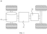
- FIG. 1 is a schematic structural diagram of a vehicle 40 according to some embodiments of this application.
- the vehicle 40 may be a fossil fuel vehicle, a natural-gas vehicle, or a new energy vehicle, where the new energy vehicle may be a battery electric vehicle, a hybrid electric vehicle, a range-extended vehicle, or the like.
- the vehicle 40 is provided with a battery 50 inside, where the battery 50 may be disposed at the bottom, front, or rear of the vehicle 40.
- the battery 50 may be configured to supply power to the vehicle 40.
- the battery 50 may be used as an operational power source for the vehicle 40.
- the vehicle 40 may further include a controller 41 and a motor 42, where the controller 41 is configured to control the battery 50 to supply power to the motor 42, for example, to satisfy power needs of start, navigation, and driving of the vehicle 40.
- the battery 50 can be used as not only the operational power source for the vehicle 40 but also a driving power source for the vehicle 40, replacing or partially replacing fossil fuel or natural gas to provide driving traction for the vehicle 40.
- FIG. 2 is a schematic structural diagram of a substrate 10 in this application.
- the coating system in an embodiment is used for coating the substrate 10, where the substrate 10 includes a first coating region 11 and a second coating region 13 adjacent to the first coating region 11.
- the first coating region 11 is a region that is divided from the surface of the substrate 10 and used for bearing the first functional layer 20 and the active material layer, where in the first coating region 11, the first functional layer 20 is applied onto the surface of the substrate 10, and the active material layer is applied onto the surface of the first functional layer 20.
- the first functional layer 20 is a primer slurry
- the second functional layer 30 is an insulation glue or insulation coating.
- the first functional layer 20 and the second functional layer 30 made of different materials are applied onto different regions before the active material layer is applied, which can effectively prevent the active material layer and the insulation slurry from being mixed, thereby avoiding an excessively thin edge or excessively thick edge of the active material layer.
- the primer slurry includes a functional material, a binder, and a conductive agent
- the binder may be selected from at least one of polyvinylidene fluoride, a vinylidene fluoride-hexafluoropropylene copolymer, polyamide, polyacrylonitrile, polyacrylate ester, polyacrylic acid, polyacrylate salt, sodium carboxymethyl cellulose, polyvinylpyrrolidone, polyvinyl ether, polymethyl methacrylate, polytetrafluoroethylene, polyhexafluoropropylene, and styrene-butadiene rubber; and the conductive agent may be selected from at least one of carbon black, carbon fiber, carbon nanotubes, graphite, graphene, metal powder, a composite conductive material, and conductive ceramic powder.
- the insulation glue is at least one of oil-based epoxy resin, bismaleimide resin, water-based polyvinylidene fluoride, and polyimide.
- the insulation coating is a metal oxide particle coating.
- a material of the insulation coating specifically includes metal oxide particles, polyvinylidene fluoride, and N-methylpyrrolidone, where a material of the metal oxide particle may be selected from aluminum oxide, titanium dioxide, zinc oxide, magnesium oxide, and a combination thereof.
- the second gravure mechanism 200 is located in a transporting direction of the substrate 10 downstream from the first gravure mechanism 100.
- the first gravure mechanism 100 and the second gravure mechanism 200 are sequentially provided in the transporting direction of the substrate 10, so that when the substrate 10 is continuously transported in a same direction, two functional layers made of different materials can be sequentially applied onto corresponding regions of the substrate 10. That the second gravure mechanism 200 is located in the transporting direction of the substrate 10 downstream from the first gravure mechanism 100 specifically means that when the substrate 10 is continuously transported in the same direction, the substrate 10 sequentially goes through the first gravure mechanism 100 and the second gravure mechanism 200.
- the first gravure mechanism 100 includes a first gravure roller 120 and a first liquid storage tank 130 loading the first functional layer 20, where the first gravure roller 120 is rotatable relative to the first liquid storage tank 130 and is partly located in the first liquid storage tank 130, and surface of the substrate 10 is tangent to that of the first gravure roller 120, where the first gravure roller 120 is rotated to pick up and apply the first functional layer 20.
- the first gravure roller 120 can pick up the first functional layer 20 that is in the first liquid storage tank 130 and print and apply it onto the first coating region 11.
- the first gravure roller 120 is located in the middle of the first liquid storage tank 130 to help the first gravure roller 120 rotate and uniformly pick up the first functional layer 20. In other embodiments, the first gravure roller 120 may alternatively be located closer to the left side or right side of the first liquid storage tank 130.
- the coating system further includes a pressing roller 110 and a winding roller for placing the substrate 10, where the winding roller is located in the transporting direction of the substrate 10 upstream from the first gravure roller 120 and is higher than the first gravure roller 120 in a vertical direction, and the pressing roller 110 and the first gravure roller 120 are disposed adjacent to each other and can simultaneously rotate in different directions to transport the substrate 10.
- actions of the first gravure roller 120 and the pressing roller 110 fully reduce contact between the slurry applied onto the first coating region 11 and air and make the first gravure roller 120 and the slurry in the first liquid storage tank 130 fully contact with each other, guaranteeing quality of gravure printing.
- the first gravure roller 120 rotates clockwise, and the pressing roller 110 simultaneously rotates counterclockwise, so that the first functional layer 20 can be printed and applied onto the first coating region 11 through the first gravure roller 120, and the substrate 10 having the first functional layer 20 can be continuously transported to the right.
- the first through roller 300 has a smooth surface.
- the first reticulated pattern 1221 is of a rhombic grid shape. In other embodiments, the first reticulated pattern 1221 may alternatively be of a circular pit shape, a rectangular grid shape, or other shapes.
- the second coating region 13 is disposed at an edge of an outer periphery of the first coating region 11.
- the substrate 10 further includes a blank region 12 located at a side of the second coating region 13 facing away from the first coating region 11.
- the surface of the first roller body 121 is provided with a first blank-leaving region 123 adjacent to the first engraving region 122, where the first blank-leaving region 123 has a smooth surface, width of the first blank-leaving region 123 being greater than that of the blank region 12.
- the provision of the blank region 12 can reserve operation space for subsequent processing procedures (for example, cutting the substrate 10).
- the first blank-leaving region 123 of the first roller body 121 can be in one-to-one correspondence with the blank region 12 of the substrate 10 to meet requirements of coating.
- the blank region 12 is a region that is divided from the surface of the substrate 10 and bears no slurry.
- the provision of the blank region 12 reserves operation space for subsequent processing procedures (for example, cutting the substrate 10).
- the first engraving region 122 is a region that is divided from the surface of the first roller body 121 and capable of carrying the first functional layer 20.
- the first blank-leaving region 123 is a region that is divided from the surface of the first roller body 121 and carries no first functional layer 20.
- the first gravure mechanism 100 further includes a scraper 140, where a blade of the scraper 140 is tangent to the surfaces of the first engraving region 122 and the first blank-leaving region 123.
- a blade of the scraper 140 is tangent to the surfaces of the first engraving region 122 and the first blank-leaving region 123.
- the second gravure mechanism 200 includes a second gravure roller 210 and a second liquid storage tank 220 loading the second functional layer 30, where the second gravure roller 210 can rotate relative to the second liquid storage tank 220 and is partly located in the second liquid storage tank 220, and the surface of the substrate 10 is tangent to that of the second gravure roller 210, where the second gravure roller 210 is rotated to pick up and apply the second functional layer 30.
- the second gravure roller 210 can pick up the second functional layer 30 that is in the second liquid storage tank 220 and print and apply it onto the second coating region 13.
- the inner diameter of the second liquid storage tank 220 is greater than or equal to the diameter of the second gravure roller 210.
- the second gravure roller 210 is partly located in the second liquid storage tank 220 and should satisfy that when the second functional layer 30 is loaded inside the second liquid storage tank 220, the second gravure roller 210 is partly soaked in the second functional layer 30 such that the second gravure roller 210 can rotate to pick up the second functional layer 30.
- the second gravure roller 210 is located in the middle of the second liquid storage tank 220 to help the second gravure roller 210 rotate and uniformly pick up the second functional layer 30.
- the second gravure roller 210 may alternatively be located closer to the left side or right side of the second liquid storage tank 220.
- the first coating region 11 is provided in a quantity of at least two
- the second coating region 13 is provided in a quantity of at least four, and edges of two sides of each of the coating regions are both provided with one second coating region 13.
- the first engraving region 122 is provided in a quantity of at least two
- the second engraving region 212 is provided in a quantity of at least four, where one second blank-leaving region 213 is disposed between every two adjacent second engraving regions 212.
- the second engraving region 212 is a region divided from the surface of the second roller body 211 and capable of carrying the second functional layer 30.
- the second roller body 211 further includes an escape groove 214, where the escape groove 214 runs through a circumferential side of the second roller body 211 to communicate with outside, width of the escape groove 214 being equal to that of the first coating region 11. In this way, it can be effectively ensured that the second functional layer 30 is not applied onto the first coating region 11, preventing the two functional layers from being mixed during application.
- the escape groove 214 is provided in a quantity of at least two, where one second blank-leaving region 213 is disposed between every two adjacent escape grooves 214, and edges of two ends of each of the escape grooves 214 are both provided with one second engraving region 212. In this way, efficiency of coating can be effectively improved.
- the escape groove 214 may alternatively be provided in a quantity of one, which can be designed based on actual needs.
- the coating system further includes a second through roller 400, where the second through roller 400 is disposed between the second gravure roller 210 and the first gravure roller 120.
- the second through roller 400 is disposed between the second gravure roller 210 and the first gravure roller 120.
- a coating system in one embodiment is used for coating the substrate 10, where the substrate 10 includes the first coating region 11, the second coating region 13 disposed at an edge of an outer periphery of the first coating region 11, and the blank region 12 located at a side of the second coating region 13 facing away from the first coating region 11.
- the coating system includes the first gravure mechanism 100 and the second gravure mechanism 200, where the second gravure mechanism 200 is located in the transporting direction of the substrate 10 downstream from the first gravure mechanism 100, the first gravure mechanism 100 is configured to apply a first functional layer 20 onto the first coating region 11, and the second gravure mechanism 200 receives the substrate 10 having the first functional layer 20 and applies a second functional layer 30 made of a material different from that of the first functional layer 20 onto the second coating region 13.
- the surface of the first engraving region 122 is provided with a plurality of first reticulated pattern 1221, width of the first engraving region 122 being equal to that of the first coating region 11.
- the first blank-leaving region 123 has a smooth surface, width of the first blank-leaving region 123 being equal to that of the blank region 12.
- the blade of the scraper 140 is tangent to the surfaces of the first engraving region 122 and the first blank-leaving region 123.
- the winding roller is located in the transporting direction of the substrate 10 upstream from the first gravure roller 120 and is higher than the first gravure roller 120 in a vertical direction.
- the pressing roller 110 and the first gravure roller 120 are disposed adjacent to each other and can rotate simultaneously in different directions to transport the substrate 10.
- the first through roller 300 is disposed between the winding roller and the pressing roller 110.
- the second gravure mechanism 200 includes the second gravure roller 210, the second liquid storage tank 220 loading the second functional layer 30, and the second through roller 400, where the second through roller 400 is disposed between the second gravure roller 210 and the first gravure roller 120.
- the second gravure roller 210 can rotate relative to the second liquid storage tank 220 and is partly located in the second liquid storage tank 220.
Landscapes
- Engineering & Computer Science (AREA)
- Chemical & Material Sciences (AREA)
- Manufacturing & Machinery (AREA)
- Materials Engineering (AREA)
- Chemical Kinetics & Catalysis (AREA)
- Electrochemistry (AREA)
- General Chemical & Material Sciences (AREA)
- Coating Apparatus (AREA)
Applications Claiming Priority (2)
| Application Number | Priority Date | Filing Date | Title |
|---|---|---|---|
| CN202221045996.4U CN217774594U (zh) | 2022-05-05 | 2022-05-05 | 涂布系统 |
| PCT/CN2023/078712 WO2023213123A1 (fr) | 2022-05-05 | 2023-02-28 | Système de revêtement |
Publications (2)
| Publication Number | Publication Date |
|---|---|
| EP4295960A1 true EP4295960A1 (fr) | 2023-12-27 |
| EP4295960A4 EP4295960A4 (fr) | 2024-07-31 |
Family
ID=83907948
Family Applications (1)
| Application Number | Title | Priority Date | Filing Date |
|---|---|---|---|
| EP23722255.9A Pending EP4295960A4 (fr) | 2022-05-05 | 2023-02-28 | Système de revêtement |
Country Status (4)
| Country | Link |
|---|---|
| US (1) | US11944995B2 (fr) |
| EP (1) | EP4295960A4 (fr) |
| CN (1) | CN217774594U (fr) |
| WO (1) | WO2023213123A1 (fr) |
Families Citing this family (3)
| Publication number | Priority date | Publication date | Assignee | Title |
|---|---|---|---|---|
| CN217774594U (zh) * | 2022-05-05 | 2022-11-11 | 宁德时代新能源科技股份有限公司 | 涂布系统 |
| CN119327667A (zh) * | 2023-07-18 | 2025-01-21 | 宁德时代新能源科技股份有限公司 | 涂布辊组件、涂布方法、极片及电池 |
| CN119230725B (zh) * | 2024-09-29 | 2025-11-07 | 四川新能源汽车创新中心有限公司 | 一种极片、极片的制备方法、二次电池和用电装置 |
Family Cites Families (45)
| Publication number | Priority date | Publication date | Assignee | Title |
|---|---|---|---|---|
| US4704296A (en) * | 1984-09-28 | 1987-11-03 | Magna-Graphics Corporation | Web coating method and apparatus |
| JPH027663Y2 (fr) * | 1985-09-06 | 1990-02-23 | ||
| CA2096392C (fr) * | 1992-05-18 | 1999-12-28 | Lawrence D. Miles | Methode et mecanisme de support d'impression |
| US5633045A (en) * | 1995-08-31 | 1997-05-27 | Xerox Corporation | Apparatus and process for coating webs using a cylindrical applicator |
| EP0876683B1 (fr) * | 1996-01-25 | 2002-09-25 | Danionics A/S | Electrode-collecteur de courant, produits stratifies pour un appareil electrochimique |
| DE19606459A1 (de) * | 1996-02-21 | 1997-08-28 | Voith Sulzer Papiermasch Gmbh | Verfahren und Vorrichtungen zum Auftragen eines flüssigen oder pastösen Mediums auf eine laufende Materialbahn |
| DE19623622A1 (de) * | 1996-06-13 | 1997-12-18 | Voith Sulzer Papiermasch Gmbh | Verfahren und Vorrichtung zur Beschichtung einer laufenden Materialbahn |
| US6033723A (en) * | 1998-02-24 | 2000-03-07 | Imation Corp. | Method and apparatus for coating plurality of wet layers on flexible elongated web |
| JP2003190855A (ja) * | 2001-12-28 | 2003-07-08 | Fuji Photo Film Co Ltd | グラビア塗布装置 |
| US6866715B1 (en) * | 2004-01-27 | 2005-03-15 | Eastman Kodak Company | Gravure method and apparatus for coating a liquid reactive to the atmosphere |
| JP2005279343A (ja) * | 2004-03-26 | 2005-10-13 | Fuji Photo Film Co Ltd | グラビア塗工装置及び光学フィルム |
| US7449216B2 (en) * | 2004-11-12 | 2008-11-11 | Eastman Kodak Company | Gravure cylinder patch coating apparatus and method |
| JP4696011B2 (ja) * | 2006-03-24 | 2011-06-08 | パナソニック株式会社 | グラビア塗工装置 |
| JP5320912B2 (ja) * | 2007-09-14 | 2013-10-23 | 株式会社リコー | 画像形成装置、泡を被塗布部材に塗布する装置 |
| JP5169395B2 (ja) * | 2008-04-07 | 2013-03-27 | トヨタ自動車株式会社 | 塗布装置及び塗布方法 |
| US8985050B2 (en) * | 2009-11-05 | 2015-03-24 | The Trustees Of Columbia University In The City Of New York | Substrate laser oxide removal process followed by electro or immersion plating |
| JP5830225B2 (ja) * | 2010-01-08 | 2015-12-09 | ユニ・チャーム株式会社 | 流体吐出装置 |
| US20110189378A1 (en) * | 2010-02-04 | 2011-08-04 | Moon So-Ii | Apparatus and method for coating a functional layer |
| US8551577B2 (en) * | 2010-05-25 | 2013-10-08 | 3M Innovative Properties Company | Layered particle electrostatic deposition process for making a coated abrasive article |
| JP5622502B2 (ja) * | 2010-09-22 | 2014-11-12 | ユニ・チャーム株式会社 | 吸収性物品に係る接着剤塗布装置、及び接着剤塗布方法 |
| DE102011118705B4 (de) * | 2010-12-16 | 2022-04-07 | Heidelberger Druckmaschinen Ag | Verfahren und Vorrichtung zur Zustandsänderung einer Folienbahn |
| US8739728B2 (en) * | 2011-04-07 | 2014-06-03 | Dynamic Micro Systems, Semiconductor Equipment Gmbh | Methods and apparatuses for roll-on coating |
| KR101328314B1 (ko) * | 2011-05-26 | 2013-11-11 | (주)제이 앤 엘 테크 | 그라비아 인쇄 제판 롤 및 그 제조 방법 |
| DK2567757T3 (da) * | 2011-09-07 | 2014-10-20 | Reifenhäuser Gmbh & Co Kg Maschinenfabrik | Apparat til at væde en materialebane med en væske |
| US9132618B2 (en) * | 2011-10-11 | 2015-09-15 | Ward Kraft, Inc. | Coating of acrylic adhesive labels |
| US9528011B2 (en) * | 2013-01-11 | 2016-12-27 | Ceraloc Innovation Ab | Digital binder and powder print |
| JP5622893B1 (ja) * | 2013-05-24 | 2014-11-12 | 富士機械工業株式会社 | 両面塗工システム |
| JP2015036140A (ja) * | 2013-08-16 | 2015-02-23 | 日本製紙パピリア株式会社 | 多色塗工紙の製造方法 |
| KR102321819B1 (ko) * | 2013-10-16 | 2021-11-03 | 스미또모 가가꾸 가부시끼가이샤 | 그라비어 롤 및 세퍼레이터의 제조 방법 그리고 세퍼레이터 |
| JP6228517B2 (ja) * | 2013-11-07 | 2017-11-08 | 利雄 村田 | 含浸装置および含浸方法 |
| GB2532255B (en) * | 2014-11-13 | 2020-04-29 | Itw Ltd | Line cleaner |
| DE102015106747B3 (de) * | 2015-04-30 | 2016-06-23 | Vits Technology Gmbh | Transportvorrichtung für eine Warenbahn |
| US10399111B2 (en) * | 2015-10-02 | 2019-09-03 | Sumitomo Chemical Company, Limited | Coating method, coating device, and functional film production method |
| EP3222766A1 (fr) * | 2016-03-22 | 2017-09-27 | Polytex Sportbeläge Produktions-GmbH | Machine de fabrication de gazon artificiel |
| IT201600102772A1 (it) * | 2016-10-13 | 2018-04-13 | Euroline Srl | Impianto e metodo per realizzare una membrana a base di bitume rivestita superficialmente da decorazioni a base di granuli |
| JP6927846B2 (ja) * | 2017-10-23 | 2021-09-01 | 株式会社ヒラノテクシード | 塗工装置 |
| KR101990704B1 (ko) * | 2017-11-24 | 2019-06-18 | 고려대학교 산학협력단 | 코팅 비드 영역이 개선된 슬롯 코팅 장치 |
| US10525687B2 (en) * | 2018-04-09 | 2020-01-07 | Xerox Corporation | Dual pressure sensitive adhesive sheet for instore signage |
| CN109317380A (zh) * | 2018-08-09 | 2019-02-12 | 深圳华美板材有限公司 | 一种半彩涂pcm钢板、生产装置及生产工艺 |
| US11384419B2 (en) * | 2019-08-30 | 2022-07-12 | Micromaierials Llc | Apparatus and methods for depositing molten metal onto a foil substrate |
| CN211404608U (zh) * | 2019-11-29 | 2020-09-01 | 无锡恩捷新材料科技有限公司 | 一种耐热粘结性低成本的涂布膜 |
| US11400479B1 (en) * | 2020-04-03 | 2022-08-02 | Michael A. Ellis | Adhesive applicator control system |
| KR102657146B1 (ko) * | 2020-04-07 | 2024-04-11 | 주식회사 엘지화학 | 그라비어 코터 테스트 장치 및 그 그라비어 코터 |
| KR102923041B1 (ko) * | 2020-08-05 | 2026-02-04 | 현대자동차 주식회사 | 이차전지용 양극전극 제조 시스템 및 이를 이용한 양극전극 제조 방법 |
| CN217774594U (zh) * | 2022-05-05 | 2022-11-11 | 宁德时代新能源科技股份有限公司 | 涂布系统 |
-
2022
- 2022-05-05 CN CN202221045996.4U patent/CN217774594U/zh active Active
-
2023
- 2023-02-28 WO PCT/CN2023/078712 patent/WO2023213123A1/fr not_active Ceased
- 2023-02-28 EP EP23722255.9A patent/EP4295960A4/fr active Pending
- 2023-09-05 US US18/461,471 patent/US11944995B2/en active Active
Also Published As
| Publication number | Publication date |
|---|---|
| EP4295960A4 (fr) | 2024-07-31 |
| WO2023213123A1 (fr) | 2023-11-09 |
| CN217774594U (zh) | 2022-11-11 |
| KR20240115901A (ko) | 2024-07-26 |
| US11944995B2 (en) | 2024-04-02 |
| US20230405628A1 (en) | 2023-12-21 |
Similar Documents
| Publication | Publication Date | Title |
|---|---|---|
| US11944995B2 (en) | Coating system | |
| US12592392B2 (en) | Electrode, method for preparing same, battery and electrical apparatus | |
| EP4411860A1 (fr) | Feuille d'électrode négative, ensemble électrode, cellule de batterie, batterie et dispositif électrique | |
| JP2007109636A (ja) | 電池用電極 | |
| JP2007280687A (ja) | 電池用電極 | |
| CN116387450A (zh) | 正极极片、电池和用电设备 | |
| CN116914137A (zh) | 负极的制造方法 | |
| US20250070265A1 (en) | Positive electrode plate, electrode assembly, secondary battery and electrical device | |
| US20240339626A1 (en) | Electrode assembly, battery cell, battery, and electric device | |
| CN217822943U (zh) | 电极极片单元、电极组件、电池及用电设备 | |
| CN118315596B (zh) | 正极片及其制备方法、二次电池和用电装置 | |
| EP4386884A1 (fr) | Feuille d'électrode et procédé de fabrication, ensemble électrode et procédé de fabrication, cellule de batterie et batterie | |
| CN117999670B (zh) | 极片及制作方法、电极组件、二次电池和用电装置 | |
| KR102955635B1 (ko) | 코팅 시스템 | |
| CN115189038A (zh) | 电极极片单元、电极组件、电池及用电设备 | |
| CN117747840A (zh) | 集流体、电极组件、电池单体、电池和用电装置 | |
| WO2023060517A1 (fr) | Plaque d'électrode, ensemble électrode, cellule de batterie, batterie et dispositif électrique | |
| CN221869038U (zh) | 涂布装置及电池生产线 | |
| US20250391884A1 (en) | Apparatus and method for manufacturing an electrode for a secondary battery | |
| CN119812438B (zh) | 电芯、二次电池和用电设备 | |
| EP4456168A1 (fr) | Ensemble électrode, élément de batterie, batterie, dispositif et appareil de fabrication | |
| CN222146273U (zh) | 复合负极片、电池单体、电池和用电装置 | |
| US20250079437A1 (en) | Secondary battery, battery, and power consuming device | |
| US20260066275A1 (en) | Electrode assembly and battery cell comprising the same | |
| WO2024174138A1 (fr) | Feuille d'électrode positive, batterie, appareil électrique et procédé de préparation de feuille d'électrode |
Legal Events
| Date | Code | Title | Description |
|---|---|---|---|
| STAA | Information on the status of an ep patent application or granted ep patent |
Free format text: STATUS: UNKNOWN |
|
| STAA | Information on the status of an ep patent application or granted ep patent |
Free format text: STATUS: THE INTERNATIONAL PUBLICATION HAS BEEN MADE |
|
| PUAI | Public reference made under article 153(3) epc to a published international application that has entered the european phase |
Free format text: ORIGINAL CODE: 0009012 |
|
| STAA | Information on the status of an ep patent application or granted ep patent |
Free format text: STATUS: REQUEST FOR EXAMINATION WAS MADE |
|
| 17P | Request for examination filed |
Effective date: 20230516 |
|
| AK | Designated contracting states |
Kind code of ref document: A1 Designated state(s): AL AT BE BG CH CY CZ DE DK EE ES FI FR GB GR HR HU IE IS IT LI LT LU LV MC ME MK MT NL NO PL PT RO RS SE SI SK SM TR |
|
| A4 | Supplementary search report drawn up and despatched |
Effective date: 20240701 |
|
| RIC1 | Information provided on ipc code assigned before grant |
Ipc: H01M 4/139 20100101ALI20240625BHEP Ipc: B05C 1/16 20060101ALI20240625BHEP Ipc: B05C 1/08 20060101ALI20240625BHEP Ipc: B05C 9/06 20060101AFI20240625BHEP |
|
| RAP1 | Party data changed (applicant data changed or rights of an application transferred) |
Owner name: CONTEMPORARY AMPEREX TECHNOLOGY(HONG KONG) LIMITED |
|
| STAA | Information on the status of an ep patent application or granted ep patent |
Free format text: STATUS: EXAMINATION IS IN PROGRESS |
|
| 17Q | First examination report despatched |
Effective date: 20250116 |
|
| DAV | Request for validation of the european patent (deleted) | ||
| DAX | Request for extension of the european patent (deleted) | ||
| GRAP | Despatch of communication of intention to grant a patent |
Free format text: ORIGINAL CODE: EPIDOSNIGR1 |
|
| STAA | Information on the status of an ep patent application or granted ep patent |
Free format text: STATUS: GRANT OF PATENT IS INTENDED |
|
| INTG | Intention to grant announced |
Effective date: 20260220 |
|
| GRAS | Grant fee paid |
Free format text: ORIGINAL CODE: EPIDOSNIGR3 |
|
| GRAA | (expected) grant |
Free format text: ORIGINAL CODE: 0009210 |
|
| STAA | Information on the status of an ep patent application or granted ep patent |
Free format text: STATUS: THE PATENT HAS BEEN GRANTED |