EP4297003A1 - Lampe de signalisation de secours dotée d'un éclairage de voie de secours supplémentaire - Google Patents
Lampe de signalisation de secours dotée d'un éclairage de voie de secours supplémentaire Download PDFInfo
- Publication number
- EP4297003A1 EP4297003A1 EP23169352.4A EP23169352A EP4297003A1 EP 4297003 A1 EP4297003 A1 EP 4297003A1 EP 23169352 A EP23169352 A EP 23169352A EP 4297003 A1 EP4297003 A1 EP 4297003A1
- Authority
- EP
- European Patent Office
- Prior art keywords
- light
- escape route
- guiding element
- light guide
- lighting
- Prior art date
- Legal status (The legal status is an assumption and is not a legal conclusion. Google has not performed a legal analysis and makes no representation as to the accuracy of the status listed.)
- Granted
Links
Images


Classifications
-
- G—PHYSICS
- G09—EDUCATION; CRYPTOGRAPHY; DISPLAY; ADVERTISING; SEALS
- G09F—DISPLAYING; ADVERTISING; SIGNS; LABELS OR NAME-PLATES; SEALS
- G09F13/00—Illuminated signs; Luminous advertising
- G09F13/18—Edge-illuminated signs
-
- G—PHYSICS
- G09—EDUCATION; CRYPTOGRAPHY; DISPLAY; ADVERTISING; SEALS
- G09F—DISPLAYING; ADVERTISING; SIGNS; LABELS OR NAME-PLATES; SEALS
- G09F13/00—Illuminated signs; Luminous advertising
- G09F13/04—Signs, boards or panels, illuminated from behind the insignia
- G09F13/0418—Constructional details
- G09F13/049—Edge illuminated signs, boards or panels
-
- G—PHYSICS
- G09—EDUCATION; CRYPTOGRAPHY; DISPLAY; ADVERTISING; SEALS
- G09F—DISPLAYING; ADVERTISING; SIGNS; LABELS OR NAME-PLATES; SEALS
- G09F7/00—Signs, name or number plates, letters, numerals, or symbols; Panels or boards
- G09F7/18—Means for attaching signs, plates, panels, or boards to a supporting structure
- G09F2007/1856—Means for attaching signs, plates, panels, or boards to a supporting structure characterised by the supporting structure
- G09F2007/186—Means for attaching signs, plates, panels, or boards to a supporting structure characterised by the supporting structure suspended, e.g. secured to the ceiling
-
- G—PHYSICS
- G09—EDUCATION; CRYPTOGRAPHY; DISPLAY; ADVERTISING; SEALS
- G09F—DISPLAYING; ADVERTISING; SIGNS; LABELS OR NAME-PLATES; SEALS
- G09F13/00—Illuminated signs; Luminous advertising
- G09F13/04—Signs, boards or panels, illuminated from behind the insignia
- G09F13/0418—Constructional details
- G09F2013/05—Constructional details indicating exit way or orientation
-
- G—PHYSICS
- G09—EDUCATION; CRYPTOGRAPHY; DISPLAY; ADVERTISING; SEALS
- G09F—DISPLAYING; ADVERTISING; SIGNS; LABELS OR NAME-PLATES; SEALS
- G09F13/00—Illuminated signs; Luminous advertising
- G09F13/18—Edge-illuminated signs
- G09F2013/1804—Achieving homogeneous illumination
- G09F2013/1836—Achieving homogeneous illumination using a frame-like light source
-
- G—PHYSICS
- G09—EDUCATION; CRYPTOGRAPHY; DISPLAY; ADVERTISING; SEALS
- G09F—DISPLAYING; ADVERTISING; SIGNS; LABELS OR NAME-PLATES; SEALS
- G09F13/00—Illuminated signs; Luminous advertising
- G09F13/20—Illuminated signs; Luminous advertising with luminescent surfaces or parts
- G09F13/22—Illuminated signs; Luminous advertising with luminescent surfaces or parts electroluminescent
- G09F2013/222—Illuminated signs; Luminous advertising with luminescent surfaces or parts electroluminescent with LEDs
-
- G—PHYSICS
- G09—EDUCATION; CRYPTOGRAPHY; DISPLAY; ADVERTISING; SEALS
- G09F—DISPLAYING; ADVERTISING; SIGNS; LABELS OR NAME-PLATES; SEALS
- G09F19/00—Advertising or display means not otherwise provided for
- G09F19/22—Advertising or display means on roads, walls or similar surfaces, e.g. illuminated
- G09F2019/225—Fire evacuation route indicating means
Definitions
- the present invention relates to an escape sign light according to the preamble of claim 1, which is designed to indicate an escape route and also to illuminate the escape route.
- escape sign lights Different types are known from the prior art, with modern and aesthetically pleasing escape sign lights generally having an external light-guiding element, on the flat sides of which at least one escape sign with an escape route direction indicated on it is attached.
- escape sign lights light is usually coupled in from a narrow side of the light-guiding element, which forms a light coupling side, with this light then being distributed within this light guide and preferably emitted mainly via the flat sides, so that the escape sign, together with the escape route direction shown, is easily and clearly recognizable .
- Such an escape sign light with a light guide protruding from a housing is, for example, from EP 2 648 178 B1 known.
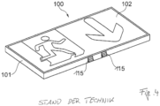
- escape sign lights can be to at least partially illuminate the escape route in addition to indicating the direction. These lights then usually have additional escape route lighting elements in the form of so-called ERI spots (Escape Route Illumination Spots), which are used to specifically illuminate areas of an escape route. As a rule, these light sources are designed in such a way that they emit light in a highly asymmetrical manner in a given direction, for example to illuminate an elongated corridor. However, these escape route lighting elements only illuminate the corresponding escape routes in an emergency situation, for example during a fire or a failure of the general power supply, while the escape sign symbol of the escape sign light itself should be illuminated continuously, i.e. even in situations in which no evacuation is required. Such an escape sign light with additional escape route lighting is available, for example DE 10 2011 082 844 A1 described and in Figure 4 shown.
- This lamp 100 has a surrounding frame 101, which serves to hold one or two transparent panes 102 for emitting light.
- the frame 101 and the disks 102 form a housing Lamp 100, in the interior of which lamps are arranged. The light from these lamps is then emitted evenly and homogeneously via the transparent panes 102, with the panes 102 containing a pictogram to show the direction of the escape route.
- ERI spots 115 are arranged at the bottom of the frame 101, which emit the light for escape route lighting. Since in this solution implemented in the prior art the frame 101 and thus the lamp 100 as a whole has a certain thickness, there is sufficient space inside the lamp housing for additional lamps and for arranging the ERI spots 115 on its underside. The alignment of the ERI spots 115 can be changed individually in order to be able to adjust the direction of the light emission.
- escape route lighting elements Since the light-guiding element is usually aligned downwards and the light emission of these escape route lighting elements is primarily directed downwards or diagonally downwards, in the solution just described, several escape route lighting elements must be arranged distributed on the outer circumference of the flange-like area in order to be able to ensure that a Escape route can be efficiently illuminated in any direction below the luminaire without the risk of the light guide element blocking or shading the light emission. This means that the space required by the lamp is increased in all directions beyond the dimensions of the light-guiding element.
- the present invention is based on the task of specifying a novel possibility which enables the positioning of additional escape route lighting elements in an escape sign light, but at the same time ensures that the Luminaire can be kept compact and still have the greatest possible flexibility with regard to the direction of light emission from the escape route lighting elements.
- the present invention represents a novel way to easily and elegantly integrate the mentioned ERI spots into an escape sign luminaire in which the light guidance technology described above is used.
- the solution is based on the idea of positioning the ERI spots in the lower side area of the light-guiding element of the luminaire and coupling each of these with the lamps for the escape route lighting via a rod-shaped light guide, which preferably runs along the outer edge of the light-guiding element.
- the rod-shaped light guide(s) are integrated into the edge region of the light-guiding element or arranged on the edge region in such a way that they only have a negligible influence on the appearance of the escape sign light.
- the lamp still appears extremely light and graceful, although it can now also be illuminated in addition to depicting an escape route.
- the light-emitting elements provided for escape route lighting are now in turn on the underside of the light-guiding element and thus on arranged on the underside of the entire luminaire, so that optimal and trouble-free light emission for escape route lighting can be achieved.
- the rod-shaped light guide extends along an edge region of the plate-shaped light-guiding element, whereby, as already described, the design should, if possible, be such that this additional light guide only insignificantly or not at all influences the appearance of the lamp.
- the light-guiding element has a receptacle for the rod-shaped light guide in its edge region, wherein in a first alternative the receptacle is formed by a groove formed in the edge region, which at least partially receives the rod-shaped light guide in a defined manner.
- the receptacle could also be formed by an elongated opening or bore extending in the edge region of the light-guiding element.
- the rod-shaped light guide is completely accommodated within the light-guiding element and is therefore not at all visible from the outside.
- Another possibility can also consist of arranging the rod-shaped light guide laterally next to the edge region of the light-guiding element, in which case its shape is preferably chosen such that it continues the contour of the light-guiding element.
- the escape route lighting element is preferably designed in such a way that it produces asymmetrical light emission.
- the direction of the light emission is preferably changeable, so that the lighting of the escape route is independent of the alignment of the light-guiding element of the escape sign light according to the invention can be done.
- the escape route lighting element firmly at one end of the light guide, in particular to design the light guide in such a way that the escape route lighting element responsible for the light emission is an integral part of the light guide.
- the light guide can then preferably be fastened in different rotational positions on the support element of the lamp or the light guide element, so that the light guide can then be arranged accordingly depending on the direction of the desired light emission.
- Another possibility is to simply arrange the escape route lighting element, which is designed in the form of a lens specially designed for asymmetrical light emission, in different rotational positions at an end region of the light guide.
- the rod-shaped light guide is also preferably held on the support element of the lamp.
- the escape sign light according to the invention has two escape route lighting elements, which are then arranged on both sides - viewed in the longitudinal direction - on the edge regions of the light-guiding element.
- the direction of light emission from the two escape route lighting elements can preferably be adjusted independently of one another, so that extremely flexible lighting of escape routes is possible.
- an escape sign light is made available, which has an extremely elegant appearance due to the light control technology used and, despite everything, offers the additional possibility of escape route lighting.
- the present invention now proposes a solution which makes it possible to realize the escape sign light in the form of a so-called disc light with a flat light-guiding element, but also to illuminate an escape route on the underside of the light.
- FIG. 1 An exemplary embodiment of a lamp according to the invention is shown in Figure 1 shown.
- the light 50 also initially has an elongated device housing 40 on its top, which is intended, for example, for attachment to a ceiling and serves to accommodate the light sources and the electronic components for operating the light sources.
- These electronic components can in particular be a corresponding driver or converter, which converts the supply voltage provided into a suitable voltage for operating the lamps.
- components for emergency power supply such as batteries or accumulators can also be arranged within this housing 40, which ensure reliable representation and lighting of an escape route even in an emergency state.
- the lighting means 45 responsible for displaying the escape route are preferably designed in the form of an elongated LED light source 45.
- this can be formed by an elongated LED board, which extends in the longitudinal direction L of the housing and whose LEDs 46 emit light towards the underside.
- the housing 40 not only serves to accommodate the components responsible for generating light, but also to hold the light-guiding element 30 responsible for the actual light emission. Accordingly, the housing 40 is designed to be open towards the underside or has at least one opening into which the upper end of the light-guiding element 30 can be inserted, with suitable measures then ensuring reliable mounting of the light-guiding element on the housing 40. These can be appropriate clamping and/or locking means, which provide a permanent and ensure reliable attachment of the light-guiding element 30 to the lamp housing 40.
- the plate-shaped light-guiding element 30 has an upper narrow side 31 when it is fastened to the housing 40 and faces the lamps 45 in such a way that the light emitted by the lamps 45 is coupled into the light-guiding element 30 via this narrow side 31.
- the narrow side 31 thus forms a light coupling area for the light-guiding element 30, which is then designed in a known manner in such a way that the light is distributed as homogeneously as possible over the entire surface of the light-guiding element 30 and emitted flatly by means of multiple reflections.
- the light is emitted via at least one flat side aligned perpendicular to the light input side 31, in the exemplary embodiment shown via the front side 32 of the light-guiding element 30, this side then also containing the pictogram 5 to represent the direction of the escape route.
- This pictogram 5 can either be a suitable direct part of the light-guiding element 30 or can be formed by a separate disk- or film-like element, which is then illuminated homogeneously by the light-guiding element 30.
- the flat light emission to represent the direction of the escape route can take place both over one and over both flat sides of the light-guiding element 30.
- the properties of the escape sign light 50 according to the invention described so far are also known from existing escape sign lights which are based on flat light guides. What is now new is that the escape route should also be illuminated, although the components provided for this purpose, in particular the components responsible for emitting light to illuminate the escape route, are not arranged on the housing 40, but instead are located at the lower end of the light-guiding element 30 and thus the lamp 50 are located.
- an escape route lighting element 10 is positioned at both ends, via which light is emitted for escape route lighting.
- the light used for escape route lighting can be emitted undisturbed, with the light emission in particular not being blocked or shaded by the plate-shaped light-guiding element 30 itself. Accordingly, in this case extremely efficient and variable lighting of an escape route can be provided.
- the lamps 48 required to illuminate the escape route - only shown in Figure 2 - are again arranged in the device housing 40.
- they can be positioned at the front and rear ends of the first lamps 45 for the escape sign lighting.
- the use of individual LEDs for escape route lighting would of course also be conceivable, although in any case it is possible to operate the first and second lamps 45 and 48 independently of one another.
- the rod-shaped light guides 20 are each arranged on opposite edge regions 34, 35 of the plate-shaped light-guiding element 30 and extend from the upper end, i.e. from the housing 40, to the lower end of the light-guiding element 30, on which the two escape route lighting elements 10 are located condition.
- the upper end faces the associated second lighting means 48, so that the corresponding light is coupled into the light guide rod 20 and forwarded to the escape route lighting elements 10 by means of internal total reflection.
- the shape of the rod-shaped light guide 20 in cross section corresponds to the cross-sectional shape of the light guide element 30, so that the two light guides 20 only slightly extend the light guide element 30 at the two end regions.
- the appearance of the light-guiding element 30 and thus the lamp 50 as a whole is only insignificantly influenced by this, so that the elegant and graceful appearance of the lamp 50 is retained.
- the rod-shaped light guides - as in Figure 2 shown - can be realized in a simple manner in the form of corresponding rods with a square cross section, in which case the thickness of these light guide rods corresponds to the thickness of the light guide element 30.
- the two rod-shaped light guides - as in Figure 1 shown - are arranged laterally next to the edge regions of the light-guiding element 30.
- the light-guiding element 30 enables a defined storage of the rod-shaped light guides 20 at the edge regions.
- corresponding receptacles are formed in the edge regions of the light-guiding element 30, in which the light guides 20 are each accommodated in a defined manner.
- a first possibility for this would be to form a corresponding channel or groove in the edge region of the light-guiding element 30, into which the associated light guide 20 is partially inserted. Bores or channels extending through the light-guiding element in the edge area would also be conceivable, which accommodate the rod-shaped light guide 20 completely within the light-guiding element 30.
- this last variant is again associated with increased production costs.
- the direction of light emission for the rescue lighting can be changed in order to be able to make a corresponding adjustment depending on the orientation of the light 50 and the direction of the escape route .
- the light for the escape route lighting is not emitted evenly in all directions, but instead in a preferred direction. This is achieved by the special design of the rescue lighting elements 10, which causes asymmetrical light emission in a preferred direction.
- FIG. 3 One possibility for realizing such an escape route lighting element 10 is here Figure 3 shown, whereby it can be seen that the light exit area 12 responsible for the light emission is designed in a Fresnell-like manner, in which case the light rays striking the flanks 13 of the area 12 and shown schematically by arrows are redirected due to internal total reflection in such a way that the light is preferably in a certain direction - in the representation to the right - is emitted. Depending on the orientation of the Fresnell-like structure 12, the light output for the escape route lighting can then be adjusted in a desired direction.
- the lens-like escape route lighting element 10 with the Fresnell structure 12 is an integral part of the light guide 20 and is formed on its underside, with the light guide 20 then being rotated overall depending on the desired light output and arranged on the light guide element 30.
- the holder through the housing 40 or the edge-side receptacle on the light guide element 30 is such that the light guide rod 20 can be arranged in several defined preferred rotational positions, for example in four rotational positions rotated by 90 ° each. A continuous alignment of the light guide 20 and thus the escape route lighting element 10 would also be conceivable.
- the person responsible for installing the lamp first inserts the light guide rod(s) 20 in the desired orientation into the corresponding receptacle(s) in the edge area of the light-guiding element 30.
- the pictogram disk, i.e. the light-guiding element 30, with the light guides 20 is then inserted into the device housing 40 and locked here by appropriate measures.
- the light guide rod is then fixed in the desired orientation and further adjustment of the direction of light emission after installation of the lamp 50 is no longer possible or is only possible by first removing the light guide element 30 with the light guides 20 from the housing 40 becomes.
- the light guide 20 itself is arranged in a fixed orientation on the light guide element 30 and the housing 40 and only at the lower end region is the ERI lens 10 intended for light emission, which is now designed as a separate component. rotated relative to the light guide 20 or can be arranged in different orientations at the lower end of the light guide 20. In this case too, it is possible to vary the direction of light emission for the escape route lighting.
- a luminaire is created which enables both the representation of an escape route direction and the illumination of the escape route, although the luminaire is characterized by its particularly elegant appearance. It should be noted that due to the fact that the light emission through the Escape route lighting elements now take place completely undisturbed, in principle it would also be possible to use only a single escape route lighting element with an associated light guide rod. However, as shown in the figures, it is preferably provided that escape route lighting elements with associated light guides are arranged on both edge regions of the light guide element.
Landscapes
- Physics & Mathematics (AREA)
- General Physics & Mathematics (AREA)
- Engineering & Computer Science (AREA)
- Theoretical Computer Science (AREA)
- Non-Portable Lighting Devices Or Systems Thereof (AREA)
Applications Claiming Priority (1)
| Application Number | Priority Date | Filing Date | Title |
|---|---|---|---|
| DE202022103416.8U DE202022103416U1 (de) | 2022-06-20 | 2022-06-20 | Rettungszeichenleuchte mit zusätzlicher Rettungswegbeleuchtung |
Publications (2)
| Publication Number | Publication Date |
|---|---|
| EP4297003A1 true EP4297003A1 (fr) | 2023-12-27 |
| EP4297003B1 EP4297003B1 (fr) | 2025-12-03 |
Family
ID=86185153
Family Applications (1)
| Application Number | Title | Priority Date | Filing Date |
|---|---|---|---|
| EP23169352.4A Active EP4297003B1 (fr) | 2022-06-20 | 2023-04-24 | Lampe de signalisation de secours dotée d'un éclairage de voie de secours supplémentaire |
Country Status (2)
| Country | Link |
|---|---|
| EP (1) | EP4297003B1 (fr) |
| DE (1) | DE202022103416U1 (fr) |
Citations (7)
| Publication number | Priority date | Publication date | Assignee | Title |
|---|---|---|---|---|
| EP0721086A1 (fr) * | 1995-01-03 | 1996-07-10 | Dr. Ing. Willing Gmbh | Plaque d'éclairage |
| US6539657B1 (en) * | 2001-05-09 | 2003-04-01 | Genlyte Thomas Group Llc | Universal edge-lit exit sign |
| US20090096630A1 (en) * | 2007-10-13 | 2009-04-16 | David Belanger | Laser lighted guidance exit indicator |
| DE102011082844A1 (de) | 2011-09-16 | 2013-03-21 | Zumtobel Lighting Gmbh | Beleuchtungsanordnung insbesondere zur Rettungswegbeleuchtung |
| EP2648178A2 (fr) | 2012-04-05 | 2013-10-09 | Zumtobel Lighting GmbH | Ensemble dýémission de lumière avec élément dýéclairage plat |
| US9589487B1 (en) * | 2014-12-22 | 2017-03-07 | Cooper Technologies Company | Combined edgelit signage and illumination |
| US20180314001A1 (en) * | 2015-11-03 | 2018-11-01 | Innotec, Corp. | Illumination assembly providing backlight and downlight |
Family Cites Families (3)
| Publication number | Priority date | Publication date | Assignee | Title |
|---|---|---|---|---|
| DE19747079A1 (de) | 1997-10-24 | 1999-05-12 | Willing Gmbh Dr Ing | Kombinationsleuchte mit Leuchtdioden |
| DE10113240A1 (de) | 2001-03-19 | 2002-10-02 | Freeflex Gmbh | Multifunktionsleuchte |
| DE102021103957A1 (de) | 2021-02-19 | 2022-08-25 | Zumtobel Lighting Gmbh | Rettungszeichenleuchte mit Rettungswegbeleuchtung |
-
2022
- 2022-06-20 DE DE202022103416.8U patent/DE202022103416U1/de active Active
-
2023
- 2023-04-24 EP EP23169352.4A patent/EP4297003B1/fr active Active
Patent Citations (7)
| Publication number | Priority date | Publication date | Assignee | Title |
|---|---|---|---|---|
| EP0721086A1 (fr) * | 1995-01-03 | 1996-07-10 | Dr. Ing. Willing Gmbh | Plaque d'éclairage |
| US6539657B1 (en) * | 2001-05-09 | 2003-04-01 | Genlyte Thomas Group Llc | Universal edge-lit exit sign |
| US20090096630A1 (en) * | 2007-10-13 | 2009-04-16 | David Belanger | Laser lighted guidance exit indicator |
| DE102011082844A1 (de) | 2011-09-16 | 2013-03-21 | Zumtobel Lighting Gmbh | Beleuchtungsanordnung insbesondere zur Rettungswegbeleuchtung |
| EP2648178A2 (fr) | 2012-04-05 | 2013-10-09 | Zumtobel Lighting GmbH | Ensemble dýémission de lumière avec élément dýéclairage plat |
| US9589487B1 (en) * | 2014-12-22 | 2017-03-07 | Cooper Technologies Company | Combined edgelit signage and illumination |
| US20180314001A1 (en) * | 2015-11-03 | 2018-11-01 | Innotec, Corp. | Illumination assembly providing backlight and downlight |
Also Published As
| Publication number | Publication date |
|---|---|
| EP4297003B1 (fr) | 2025-12-03 |
| DE202022103416U1 (de) | 2023-10-09 |
Similar Documents
| Publication | Publication Date | Title |
|---|---|---|
| EP1891368B1 (fr) | Dispositif d'eclairage comprenant une source de lumiere principale et une source de lumiere supplementaire | |
| EP2375128B1 (fr) | Luminaire dotée de DEL et de lentilles attribuées aux DEL | |
| EP1979668B1 (fr) | Lampe comprenant un logement sous forme de boitier et element de sortie d'eclairage | |
| AT512127B1 (de) | Leuchte | |
| EP2556289B1 (fr) | Lampe à boîtier allongé | |
| EP4297003B1 (fr) | Lampe de signalisation de secours dotée d'un éclairage de voie de secours supplémentaire | |
| WO2023198456A1 (fr) | Élément de guidage de lumière pour luminaire de secours | |
| EP1022188A2 (fr) | Feux de véhicule | |
| EP2472178B1 (fr) | Lampe intégrée | |
| EP2175188B1 (fr) | Eclairage | |
| DE202008012463U1 (de) | Anordnung zur Bildung einer länglichen Lichtquelle | |
| DE10321282B4 (de) | Wandleuchte | |
| EP2466573B1 (fr) | Eclairage | |
| EP2518389B1 (fr) | Élément optique longitudinal et agencement d'émission de lumière avec un élément optique | |
| EP1538394B1 (fr) | Lampe avec cadre à profil | |
| EP2176583A1 (fr) | Éclairage à grille pour l'émission de lumière | |
| DE10315771A1 (de) | Leuchte mit geschlossener Lichtabstrahlfläche | |
| EP3924664B1 (fr) | Arrangement d'émission de lumière comprenant un élément de guidage de lumière en forme de plaque | |
| EP2833050B1 (fr) | Lampe suspendue dotée d'une source lumineuse destinée à produire un éclairage indirect | |
| EP2994690B1 (fr) | Luminaire équipé d'un boîtier comportant plusieurs orifices de rayonnement de lumière | |
| DE102023135927A1 (de) | Sicherheitszeichenleuchte mit lichtleiterelement | |
| DE20319233U1 (de) | Konstruktion zur Erzeugung von Lichteffekten mit transparenten Luftkissen und Leuchten | |
| DE102019113527A1 (de) | Kraftfahrzeug-Leuchtanordnung mit zwei überlappenden Leuchteinheiten sowie Kraftfahrzeug | |
| EP1843082A1 (fr) | Plafonnier, en particulier pour utilisation dans un couloir |
Legal Events
| Date | Code | Title | Description |
|---|---|---|---|
| PUAI | Public reference made under article 153(3) epc to a published international application that has entered the european phase |
Free format text: ORIGINAL CODE: 0009012 |
|
| STAA | Information on the status of an ep patent application or granted ep patent |
Free format text: STATUS: THE APPLICATION HAS BEEN PUBLISHED |
|
| AK | Designated contracting states |
Kind code of ref document: A1 Designated state(s): AL AT BE BG CH CY CZ DE DK EE ES FI FR GB GR HR HU IE IS IT LI LT LU LV MC ME MK MT NL NO PL PT RO RS SE SI SK SM TR |
|
| STAA | Information on the status of an ep patent application or granted ep patent |
Free format text: STATUS: REQUEST FOR EXAMINATION WAS MADE |
|
| 17P | Request for examination filed |
Effective date: 20240606 |
|
| RBV | Designated contracting states (corrected) |
Designated state(s): AL AT BE BG CH CY CZ DE DK EE ES FI FR GB GR HR HU IE IS IT LI LT LU LV MC ME MK MT NL NO PL PT RO RS SE SI SK SM TR |
|
| GRAP | Despatch of communication of intention to grant a patent |
Free format text: ORIGINAL CODE: EPIDOSNIGR1 |
|
| STAA | Information on the status of an ep patent application or granted ep patent |
Free format text: STATUS: GRANT OF PATENT IS INTENDED |
|
| INTG | Intention to grant announced |
Effective date: 20250922 |
|
| GRAS | Grant fee paid |
Free format text: ORIGINAL CODE: EPIDOSNIGR3 |
|
| GRAA | (expected) grant |
Free format text: ORIGINAL CODE: 0009210 |
|
| STAA | Information on the status of an ep patent application or granted ep patent |
Free format text: STATUS: THE PATENT HAS BEEN GRANTED |
|
| AK | Designated contracting states |
Kind code of ref document: B1 Designated state(s): AL AT BE BG CH CY CZ DE DK EE ES FI FR GB GR HR HU IE IS IT LI LT LU LV MC ME MK MT NL NO PL PT RO RS SE SI SK SM TR |
|
| REG | Reference to a national code |
Ref country code: CH Ref legal event code: F10 Free format text: ST27 STATUS EVENT CODE: U-0-0-F10-F00 (AS PROVIDED BY THE NATIONAL OFFICE) Effective date: 20251203 Ref country code: GB Ref legal event code: FG4D Free format text: NOT ENGLISH |
|
| P01 | Opt-out of the competence of the unified patent court (upc) registered |
Free format text: CASE NUMBER: UPC_APP_0011651_4297003/2025 Effective date: 20251030 |
|
| REG | Reference to a national code |
Ref country code: DE Ref legal event code: R096 Ref document number: 502023002338 Country of ref document: DE |
|
| REG | Reference to a national code |
Ref country code: IE Ref legal event code: FG4D Free format text: LANGUAGE OF EP DOCUMENT: GERMAN |
|
| REG | Reference to a national code |
Ref country code: DE Ref legal event code: R084 Ref document number: 502023002338 Country of ref document: DE |
|
| REG | Reference to a national code |
Ref country code: NL Ref legal event code: MP Effective date: 20251203 |
|
| PG25 | Lapsed in a contracting state [announced via postgrant information from national office to epo] |
Ref country code: ES Free format text: LAPSE BECAUSE OF FAILURE TO SUBMIT A TRANSLATION OF THE DESCRIPTION OR TO PAY THE FEE WITHIN THE PRESCRIBED TIME-LIMIT Effective date: 20251203 |
|
| REG | Reference to a national code |
Ref country code: LT Ref legal event code: MG9D |
|
| PG25 | Lapsed in a contracting state [announced via postgrant information from national office to epo] |
Ref country code: NO Free format text: LAPSE BECAUSE OF FAILURE TO SUBMIT A TRANSLATION OF THE DESCRIPTION OR TO PAY THE FEE WITHIN THE PRESCRIBED TIME-LIMIT Effective date: 20260303 |
|
| PG25 | Lapsed in a contracting state [announced via postgrant information from national office to epo] |
Ref country code: FI Free format text: LAPSE BECAUSE OF FAILURE TO SUBMIT A TRANSLATION OF THE DESCRIPTION OR TO PAY THE FEE WITHIN THE PRESCRIBED TIME-LIMIT Effective date: 20251203 Ref country code: HR Free format text: LAPSE BECAUSE OF FAILURE TO SUBMIT A TRANSLATION OF THE DESCRIPTION OR TO PAY THE FEE WITHIN THE PRESCRIBED TIME-LIMIT Effective date: 20251203 |
|
| PG25 | Lapsed in a contracting state [announced via postgrant information from national office to epo] |
Ref country code: RS Free format text: LAPSE BECAUSE OF FAILURE TO SUBMIT A TRANSLATION OF THE DESCRIPTION OR TO PAY THE FEE WITHIN THE PRESCRIBED TIME-LIMIT Effective date: 20260303 |