EP4300248B1 - Verfahren zur steuerung einer kolonnenkombination - Google Patents
Verfahren zur steuerung einer kolonnenkombination Download PDFInfo
- Publication number
- EP4300248B1 EP4300248B1 EP23182154.7A EP23182154A EP4300248B1 EP 4300248 B1 EP4300248 B1 EP 4300248B1 EP 23182154 A EP23182154 A EP 23182154A EP 4300248 B1 EP4300248 B1 EP 4300248B1
- Authority
- EP
- European Patent Office
- Prior art keywords
- vehicle
- following
- value
- leading
- deceleration
- Prior art date
- Legal status (The legal status is an assumption and is not a legal conclusion. Google has not performed a legal analysis and makes no representation as to the accuracy of the status listed.)
- Active
Links
Images

Classifications
-
- G—PHYSICS
- G05—CONTROLLING; REGULATING
- G05D—SYSTEMS FOR CONTROLLING OR REGULATING NON-ELECTRIC VARIABLES
- G05D1/00—Control of position, course, altitude or attitude of land, water, air or space vehicles, e.g. using automatic pilots
- G05D1/02—Control of position or course in two dimensions
- G05D1/021—Control of position or course in two dimensions specially adapted to land vehicles
- G05D1/0287—Control of position or course in two dimensions specially adapted to land vehicles involving a plurality of land vehicles, e.g. fleet or convoy travelling
- G05D1/0291—Fleet control
- G05D1/0295—Fleet control by at least one leading vehicle of the fleet
Definitions
- the present invention relates generally to vehicle platooning. More particularly, the present invention relates to systems and methods for dynamically adjusting platoon control variables such as respective following distances for a number of vehicles such as tractor trailers.
- driver assistive vehicle platooning are well-established, as are the benefits of a reduced following distance between respective vehicles in a platoon orientation. For example, minimizing following distances can result in reduced aerodynamic drag for all vehicles in a platoon, and thereby improve respective fuel economies. At highway speeds, aerodynamic drag may be characterized as the greatest consumer of vehicle power, well in excess of the combined effects of rolling friction resistance and vehicle accessory losses. Test results have indicated that vehicles consistently achieve increased benefits correlating to closer following distances, although the energy-saving benefits may vary depending on the respective vehicle position within a platoon.
- advanced braking control systems are to be implemented, along with vehicle-to-vehicle communication, to facilitate vehicle platooning while at the same time reducing the associated following distances to a maximal extent.
- inter vehicle communication is established, to exchange control variables necessary for the calculus of platoon following distances. These distances are determined, amongst others, by delay times in the vehicle communication; by road conditions, truck load, and tire and brake system conditions.
- a challenge remains to safely reduce the following distance between vehicles to its minimal level.
- a following vehicle in a platoon must implement a safe following distance, which accounts for the successive detection of braking actions by the preceding vehicle.
- a conventional Automatic Emergency Braking system which is normally equipped for non-platooning driving may, due to legally required (pre) warning phases of an emergency braking event, introduce time delays which can be too long for a vehicle in platooning mode to guarantee capability to prevent crashing into the preceding vehicle. Furthermore, while a cooperating adaptive cruise control system may provide a comfortable drive mode when vehicles are following each other in platoon mode in normal circumstances, such a system may be not sufficiently responsive to provide an emergency braking protocol when required in exceptional cases.
- US 10 921 821 B2 discloses a method according to the preamble of claim 1.
- US 2019/384322 A1 discloses an arbitrator.
- a method of controlling a platoon combination of a leading vehicle immediately preceding a following vehicle comprising equipping said leading and following vehicles with a vehicle longitudinal motion control system and a vehicle-to-vehicle communication system, said vehicle-to-vehicle communication system communicating a deceleration value of the leading vehicle from the leading vehicle to the following vehicle.
- the vehicle longitudinal motion control comprises an adaptive cruise control module, programmed to calculate a first deceleration value of the following vehicle; based on the deceleration value received from the leading vehicle through the vehicle-to-vehicle communication system.
- the vehicle longitudinal motion control system further comprises a cooperative collision avoidance module, programmed to calculate a second deceleration value in order to maintain a safe following distance and/or time headway of the following vehicle with respect to the leading vehicle in the platoon, in order to realize a full stop of the following vehicle to avoid colliding with the preceding vehicle.
- the vehicle longitudinal motion control comprises an arbitrator, programmed to output a maximum of said calculated first and second deceleration values; and the vehicle longitudinal motion control comprises a brake controller, programmed to execute an actual deceleration value based on the output of the arbitrator.
- platoon control executed by a vehicle longitudinal motion control system of the above kind maintains a minimum safe following distance to prevent a collision, where the adaptive cruise control module, by its inherent limitations of delay and deceleration limitation, is unable to do so.
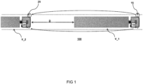
- a vehicle platooning control system 100 including a leading vehicle V_1 and following vehicle V_2 in a platoon combination.
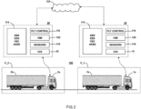
- the leading vehicle V_1 and following vehicle V_2 are each equipped with a vehicle longitudinal motion control system schematically indicated at 10, 20 respectively and a vehicle-to-vehicle communication system schematically indicated at 15, 25 respectively; further exemplified in Figure 2 .
- the vehicle longitudinal motion control system 20 is configured to calculate an intervehicle distance / following distance D and/or time headway of the following vehicle V_2 with respect to the leading vehicle V_1 in the platoon.
- the vehicle-to-vehicle communication system may be configured to communicate the predicted deceleration of the leading vehicle, from the leading vehicle V_1, via its vehicle-to-vehicle communication system 15, to vehicle-to-vehicle communication system 25 of the following vehicle V_2.
- the vehicle-to-vehicle communication system can be any suitable system, typically communicating via radio signals or any other suitable form, in particular WiFi and may be provided with redundant communication facilities.
- FIG. 2 shows vehicle platooning control system 100 as disclosed herein may be provided with respect to at least a first vehicle V_1 (truck 1a and trailer 1b) and a second vehicle V_2 (truck 2a; trailer 2b).
- the vehicle platooning control aspects may be implemented solely via components residing upon the vehicles V_1 V_2 themselves.
- the vehicles may each be configured to communicate not only directly with each other but further via a communications network 124 e.g. with a remote computing network including for example one or more servers configured to implement platooning control aspects.
- Each vehicle in a potential platoon may be considered to have at least certain minimum structural components in order for various embodiments of the present disclosure to be implemented.
- the vehicles may include one or more vehicle longitudinal motion control systems 10, 20, condition sensors 116, local platooning control circuitry/processor 118 functionally linked to the braking control systems 114, and a user interface 120 which typically includes graphical display components but may also include any other user input/output elements as may be necessary or desirable for conveying information to and from the driver of the respective vehicle.
- the vehicle longitudinal motion control and platoon implementation systems 10, 20 as necessary to provide the recited functions herein may be selected from various systems as are known to those skilled in the art including but not limited to an Anti-Lock Braking System (“ABS”) for the vehicle, and to the extent that the vehicle includes a tractor and a trailer further an ABS for the respective trailer 1b/2b, Vehicle Stability Control (“VSC"), Advanced Emergency Braking Systems AEBS, Vehicle-to-Vehicle/Infrastructure Communications (“V2X”) 15, 25, Electronic Braking System (“EBS”), and the like.
- a trailer ABS may generally be considered to be configured for communication of ABS events with at least the respective tractor.
- otherwise conventional braking control systems 114 such as the AEBS for example, may be supplemented or otherwise configured to include hardware, software, or some combination thereof so as to execute a vehicle platooning algorithm in accordance with the present disclosure.
- vehicle platooning algorithms and components may be separately associated with control block 118.
- the braking control systems, and more particularly the AEBS may be implemented for distance measurement using techniques as are known to those of skill in the art.
- the vehicle sensors 116 may be configured to provide at least certain information as needed to execute functions for a particular embodiment of the platooning control system, including for example a following distance between a given pair of vehicles, relative velocity and acceleration/deceleration values for the respective vehicle, a pressure value with respect to a braking actuator for the respective vehicle, front and rear radar/camera/LIDAR/sensors for distance measurement, image capturing and the like, side lane monitoring devices, alternative pressure sensors integrally mounted to or associated with solenoid valves, etc.
- Specifically platooning control block 118 may comprise a processor configured to execute a computer program product and thereby direct the performance of operations comprising: deriving for the respective vehicle a current gross combination weight value; relating the current gross combination weight of the respective vehicle to a maximum brake value and to a minimum brake value derived from a lookup table.
- a current gross combination weight value can be derived from sensors 116 by means known in the art, e.g. wherein the gross combination weight value of each leading and following vehicle is derived from an electronic brake system or transmission system of the said each leading and following vehicle.
- a 'safe distance' (its nominal value) may be calculated by any suitable control algorithm that supersedes a regular adaptive cruise control and may be based on a number of considerations not discussed in detail, such as an augmentation of this nominal value to correct for a delay in the vehicle-to-vehicle communication; and an offset defining a minimum following distance at standstill.
- the safe distance will be calculated based on actual vehicle speeds, wherein increasing speeds will require an increasing following distance in order to be able to anticipate a full stop scenario of the leading vehicle.
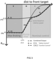
- Figure 3 illustrates schematic individual output response curves A and B of a vehicle longitudinal motion control system that comprises a cooperative collision avoidance module.
- the shown schematic has a ⁇ distance to front target' on the x-axis, and a corresponding (negative) deceleration value Axbr as corresponding deceleration value.
- a first response curve A of first deceleration values (i) is provided by a (coordinated) adaptive cruise controller (CACC) programmed to calculate a first deceleration value of the following vehicle; based on the deceleration value received from the leading vehicle by the vehicle-to-vehicle system.
- CACC coefficientd adaptive cruise controller
- the adaptive cruise controller (see further below) outputs a response curve A of deceleration values (i) that is typically limited, in the example to a threshold value that ranges between 1.5 and 3 m/s 2 for an empty vehicle.
- a second response curve B of second deceleration values (ii) is shown, programmed by a cooperative collision avoidance (CCA) module, that calculates these (second) deceleration values for maintaining a safe following distance and/or time headway of the following vehicle with respect to the leading vehicle in the platoon, in particular in order to realize a full stop of the following vehicle.
- CCA cooperative collision avoidance
- response curve B is limited to a maximum attainable vehicle deceleration (in the figure of -6 m/s 2 ), which effectively means that a following vehicle should not be in the 'forbidden' area II that is limited between 0 and the calculated minimal safe distance, which is vehicle speed dependent.
- the brake controller of the vehicle will be instructed to execute an emergency brake event based on a maximum brake power of the vehicle.
- the Figure 3 shows a ⁇ bumpstop area' III wherein a deceleration value is provided by a third deceleration value calculated by a bumpstop control module programmed to replace the second deceleration value by a third deceleration value of the following vehicle; if the second deceleration value exceeds a first threshold value, wherein the third deceleration value is larger than the calculated first deceleration value.
- the arbitrator will thus not provide a second braking value that is (close to) the maximum brake value T2, but will provide a third deceleration value (iii) that gradually increase braking performance with decreasing following distance, to try to keep up with decelerations of a preceding vehicle without executing an emergency brake stop, but at decelerations considerably higher than attainable through CACC brake control.
- the third acceleration value (iii) may range, as long as the minimum value of a 'safe distance' is not violated, depending on a vehicle distance between leading and following vehicles, between 2.5 m/s 2 and a maximum braking value, for an empty vehicle.
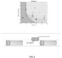
- Figure 4 shows an exemplary chart which relates relative vehicle speeds and relative vehicle distances to the identified 'safe distance area' II, wherein the CCA controller takes over in the arbitration for a maximum deceleration value; a normal area I usually controlled by the CACC controller, and a bumpstop area III, which is an intermediate area with increasing deceleration values, e.g. between -1 and -4, still below a maximum deceleration value of the following vehicle, which in the Figure plateaus at a value of -4.
- the bumpstop area III offers a convenient way to handle collision avoidance scenarios without performing full stop emergency braking. For instance in one scenario a cut-in vehicle suddenly limits the intervehicle distance from a 'safe distance' to a distance that is below the safe distance. However, instead of executing an emergency braking action, which would be executed based solely on the distance to the preceding vehicle, the CCA controller is programmed to delay the maximum brake instruction to the brake controller in the event of a registered cut-in vehicle.
- the preceding vehicle is assumed to have a constant speed, in particular, substantially equal to the following vehicle without any deceleration.
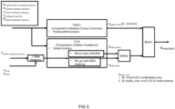
- FIG 5 shows a schematic system layout for carrying out the method as previously disclosed.
- a variety of actual data is processed for inputting to a CACC module, which is the coordinated adaptive cruise control module that is programmed to calculate a first deceleration value of the following vehicle; based on the deceleration value received from the leading vehicle by the vehicle-to-vehicle system.
- the CACC is not equipped for handling collision risks, but provides an optimized following behavior for fuel and comfort; and is focused on ⁇ string stability' which avoids oscillations in acceleration and braking.
- the data, in particular accelerations and speeds of the leading and following vehicle are inputted in parallel into the CACC controller, adapted to provide a cruise control function, and into the CCA controller, adapted to provide a safe following distance or time headway of the following vehicle.
- a relative following distance Drelative of the following vehicle is monitored by onboard sensors. It is noted that the CCA control is not immediately dependent on wireless input, but calculated a safe distance based, e.g. on maximum brake values of the leading and following vehicles, -a f , max and -a l,max . that may be transmitted prior
- the CCA module calculates the safe distance from several physical quantities, including maximum brake decelerations of leading and following vehicles, and actual speed of the leading and following vehicles; in order to bring the following vehicle to full stop when required.
- a maximum arbitration is carried out for the bump stop and max braking calculation as a second input to a MAX1 arbitrator programmed to output a maximum of said calculated first (a brake_CACC ) and second deceleration (a brake_Max )values.
- the second deceleration value a brake_Max may be replaced by a third deceleration value a brake_Bump by means of another arbitrator MAX2; if the second deceleration value a brake_Max exceeds a first threshold value, and the third deceleration value a brake_Bump is larger than the calculated second deceleration value a brake_Max .
- such threshold value can be provided by the calculated second deceleration value. At all times, the deceleration value is lower or equal than the maximum brake deceleration of the following vehicle.
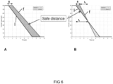
- Figure 6 shows two scenarios for max braking events of a leading and following vehicle.
- a cooperative collision avoidance module may calculate the safe distance from a difference of terms including maximum brake decelerations of leading and following vehicles and actual speed of the leading and following vehicles.
- the leading vehicle has a maximum higher brake performance and will reach standstill first.
- the following vehicle has to maintain a distance at all times, since it will still be braking when the leading vehicle reaches standstill (e.g. at Time 7 seconds) and the following vehicle will only reach standstill at Time 9 seconds.
- the invention is not limited to a particular way for calculating a safe distance.
- it may be based on exemplary values of a lookup table relating a current gross combination weight (GCW) of a vehicle to an estimated maximum brake value and to an estimated minimum brake value of the vehicle wherein the lookup table relates a gross combination weight of a vehicle to a maximum brake performance value that estimates a maximum deceleration value of the performance truck for said gross combination weight value and a minimum brake value that estimates a minimum deceleration value of the truck for said gross combination weight value.
- GGW current gross combination weight
- the brake performance estimation can be used, for instance, to calculate a safe time headway for platooning.
- the brake performance estimator parameters i.e. nominal maximum brake value and uncertainty bands
- a safe time headway for platooning can be calculated based on the brake performance parameters applied to the host and preceding vehicle, and an additional assumption on the (communication) time delay between the start of a braking action of the preceding vehicle and that braking action arriving via V2X at the host vehicle.
- This scheme has the advantage that the influence of all other maximum brake determining factors, such as the brake supply pressure, brake temperature, load distribution, tires etc. are implicitly accounted for in this method.
- maximum and minimum brake values are kept constant for gross combination weight values below a mimimum gross combination value., e.g. below a minimum value of 7 tonnes, which is typically the weight of an empty truck without trailer, but this could be a different value, e.g. a range in the 5-9 tonnes and above (see example 3A).
- maximum and minimum brake performance values are kept constant for gross combination weight values exceeding a maximum gross combination weight value of the vehicle. e.g. for a maximum gross combination weight value determined by legislation, typically between 40 and 50 ton.
- tests are performed with different tractors, different brake supply pressures (e.g. ranging between 8.5 -12.5 bar), brake temperatures (e.g. cold brakes and brakes about 100/200 °C), tires (e.g. lower and higher pressures), load distributions and conditions (empty, half full, full), and weather conditions (wet/dry). It is found that these varied conditions all fit in a bandwidth between a minimum and maximum deceleration value.
- brake temperature conditions e.g. cold brakes and brakes about 100/200 °C
- tires e.g. lower and higher pressures
- load distributions and conditions empty, half full, full
- weather conditions wet/dry
- the safe following distance and/or time headway are augmented to correct for a delay in the vehicle-to-vehicle communication; and an offset defining a minimum following distance at standstill.
- a delay could range between 0.05 and 0.2 seconds. While the headway can be almost fully attributed for a brake headway, where a standstill would leave no headway, it is desirable that the driver still has some headway on standstill, for instance, about 1 to 7 meters.
- module as in “storage module” or “receiver module” or “control module” is used to emphasize the modular character of these units, i.e. the functionality of the system may be separated into independent, interchangeable units.
- user interface may comprise one or more hardware elements configured to perform operational acts in accordance with the present systems and methods, such as to provide control signals to the various other module components.
- the processor may be a dedicated processor for performing in accordance with the present system or may be a general-purpose processor wherein only one of many functions operate for performing in accordance with the present system.
- the processor may operate utilizing a program portion, multiple program segments, or may be a hardware device utilizing a dedicated or multi-purpose integrated circuit. Any type of processor may be used such as a dedicated or shared one.
- the processor may include micro-controllers, central processing units (CPUs), digital signal processors (DSPs), ASICs, or any other processor(s) or controller(s) such as digital optical devices, or analog electrical circuits that perform the same functions, and employ electronic techniques and architecture.
- the controller or processor may further comprise a memory that may be part of or operationally coupled to the controller.
- the memory may be any suitable type of memory where data is stored. Any medium known or developed that can store and/or transmit information suitable for use with the present systems and methods may be used as a memory.
- the memory may also store user preferences and/or application data accessible by the controller for configuring it to perform operational acts in accordance with the present systems and methods.
Landscapes
- Engineering & Computer Science (AREA)
- Aviation & Aerospace Engineering (AREA)
- Radar, Positioning & Navigation (AREA)
- Remote Sensing (AREA)
- Physics & Mathematics (AREA)
- General Physics & Mathematics (AREA)
- Automation & Control Theory (AREA)
- Regulating Braking Force (AREA)
- Traffic Control Systems (AREA)
Claims (9)
- Verfahren zum Steuern einer Kolonnenkombination eines führenden Fahrzeugs, das sich direkt vor einem folgenden Fahrzeug befindet, das Folgendes umfasst- Ausrüsten des führenden und des folgenden Fahrzeugs mit einem Fahrzeug-Längsbewegungssteuersystem und einem Fahrzeug-zu-Fahrzeug-Kommunikationssystem,- wobei das Fahrzeug-zu-Fahrzeug-Kommunikationssystem einen Verzögerungswert des vorausfahrenden Fahrzeugs von dem vorausfahrenden Fahrzeug an das nachfolgende Fahrzeug übermittelt;- wobei die Fahrzeug-Längsbewegungssteuerung ein adaptives Tempomat-Steuermodul umfasst, das dazu programmiert ist, einen ersten Verzögerungswert des nachfolgenden Fahrzeugs basierend auf dem Verzögerungswert zu berechnen, der von dem vorausfahrenden Fahrzeug empfangen wird, durch das Fahrzeug-zu-Fahrzeug-System;- dadurch gekennzeichnet, dass das Fahrzeug-Längsbewegungssteuersystem ein kooperatives Kollisionsvermeidungsmodul umfasst, das dazu programmiert ist, einen zweiten Verzögerungswert zu berechnen, um eine sichere Folgedistanz und/oder einen sicheren zeitlichen Vorsprung des nachfolgenden Fahrzeugs in Bezug auf das vorausfahrende Fahrzeug in der Kolonne aufrechtzuerhalten;- und wobei die Fahrzeug-Längsbewegungssteuerung einen Arbitrator umfasst, der dazu programmiert ist, ein Maximum des berechneten ersten und zweiten Verzögerungswerts auszugeben; und- die Fahrzeug-Längsbewegungssteuerung eine Bremssteuervorrichtung umfasst, die dazu programmiert ist, einen tatsächlichen Verzögerungswert basierend auf der Ausgabe des Arbitrators auszuführen.
- Verfahren nach Anspruch 1, wobei das kooperative Kollisionsvermeidungsmodul eine sichere Distanz aus einer Differenz von Termen berechnet, die die maximalen Bremsverzögerungen des vorausfahrenden und des nachfolgenden Fahrzeugs und die tatsächliche Geschwindigkeit des vorausfahrenden und des nachfolgenden Fahrzeugs beinhalten, um das nachfolgende Fahrzeug zum Stillstand zu bringen.
- Verfahren nach einem vorstehenden Anspruch, wobei das kooperative Kollisionsvermeidungsmodul ferner ein Bumpstop-Steuermodul umfasst, das dazu programmiert ist, den zweiten Verzögerungswert durch einen dritten Verzögerungswert des nachfolgenden Fahrzeugs zu ersetzen, falls der zweite Verzögerungswert einen ersten Schwellenwert überschreitet, wobei der dritte Verzögerungswert größer als der berechnete zweite Verzögerungswert ist.
- Verfahren nach Anspruch 3, wobei der dritte Beschleunigungswert niedriger ist als der maximale Bremswert des nachfolgenden Fahrzeugs.
- Verfahren nach Anspruch 4, wobei der dritte Beschleunigungswert in Abhängigkeit von einer Fahrzeugdistanz zwischen dem vorausfahrenden und dem nachfolgenden Fahrzeug von -1 m/s2 und bis zu einem maximalen Bremswert für ein leeres Fahrzeug reicht.
- Verfahren nach einem der Ansprüche 3 oder 4, wobei der erste Schwellenwert von -1 bis -3 m/s2 für ein leeres Fahrzeug reicht.
- Verfahren nach einem vorstehenden Anspruch, wobei der Arbitrator dazu programmiert ist, die Ausgabe des Arbitrators an die Bremssteuervorrichtung im Falle eines registrierten dazwischen hineinfahrenden Fahrzeugs zu verzögern.
- Verfahren nach Anspruch 1, wobei der Wert des kombinierten Gesamtgewichts jedes des vorausfahrenden und des nachfolgenden Fahrzeugs aus einem elektronischen Bremssystem, Übertragungssystem oder anderen Kolonnensteuersystem jedes des vorausfahrenden und des nachfolgenden Fahrzeugs abgeleitet wird.
- Verfahren nach einem vorstehenden Anspruch, wobei die sichere Folgedistanz erhöht wird, um einen Versatz zu korrigieren, der einen Mindestfolgeabstand bei Stillstand definiert.
Applications Claiming Priority (1)
| Application Number | Priority Date | Filing Date | Title |
|---|---|---|---|
| NL2032320A NL2032320B1 (en) | 2022-06-29 | 2022-06-29 | Method of controlling a platoon combination |
Publications (3)
| Publication Number | Publication Date |
|---|---|
| EP4300248A1 EP4300248A1 (de) | 2024-01-03 |
| EP4300248C0 EP4300248C0 (de) | 2024-12-25 |
| EP4300248B1 true EP4300248B1 (de) | 2024-12-25 |
Family
ID=83271241
Family Applications (1)
| Application Number | Title | Priority Date | Filing Date |
|---|---|---|---|
| EP23182154.7A Active EP4300248B1 (de) | 2022-06-29 | 2023-06-28 | Verfahren zur steuerung einer kolonnenkombination |
Country Status (2)
| Country | Link |
|---|---|
| EP (1) | EP4300248B1 (de) |
| NL (1) | NL2032320B1 (de) |
Family Cites Families (3)
| Publication number | Priority date | Publication date | Assignee | Title |
|---|---|---|---|---|
| US10520952B1 (en) * | 2011-07-06 | 2019-12-31 | Peloton Technology, Inc. | Devices, systems, and methods for transmitting vehicle data |
| US10921821B2 (en) * | 2017-12-21 | 2021-02-16 | Bendix Commercial Vehicle Systems Llc | Determining and using braking capabilities of vehicles for platooning deceleration operations |
| DE102018118744A1 (de) * | 2018-08-02 | 2020-02-06 | Wabco Gmbh | Verfahren zum Einstellen einer Fahrzeug-Verzögerung eines Fahrzeuges in einem Platoon sowie Platooning-Regelsystem und Fahrzeug |
-
2022
- 2022-06-29 NL NL2032320A patent/NL2032320B1/en active
-
2023
- 2023-06-28 EP EP23182154.7A patent/EP4300248B1/de active Active
Also Published As
| Publication number | Publication date |
|---|---|
| EP4300248A1 (de) | 2024-01-03 |
| EP4300248C0 (de) | 2024-12-25 |
| NL2032320B1 (en) | 2024-01-16 |
Similar Documents
| Publication | Publication Date | Title |
|---|---|---|
| US8396642B2 (en) | Adaptive cruise control system | |
| US7739023B2 (en) | Adaptive cruise control system and method for vehicle | |
| KR102417906B1 (ko) | 선두 차량의 군집 주행 제어 장치 및 방법 | |
| US11414060B2 (en) | Method and vehicle for activating an autonomous braking maneuver | |
| CA2860892C (en) | Method for determining an emergency braking situation of a vehicle | |
| US7493200B2 (en) | Automatic brake system for a vehicle | |
| US9081387B2 (en) | Method and device for the prediction and adaptation of movement trajectories of motor vehicles | |
| US11938924B2 (en) | Driving assistance control apparatus for vehicle, driving assistance control system for vehicle, and driving assistance control method for vehicle | |
| US20070282530A1 (en) | Method And Device For Warning The Driver Of A Motor Vehicle | |
| US20100280726A1 (en) | Prevention of a rear crash during an automatic braking intervention by a vehicle safety system | |
| CN110001647A (zh) | 车辆触发变道方法、系统及计算机可读存储介质 | |
| JP2007523787A (ja) | 自動車の間隔制御システム | |
| JP7200786B2 (ja) | 車両の制動制御装置 | |
| EP3602512B1 (de) | Verfahren für eine reihe mit mehreren fahrzeugen in einer kolonne | |
| US20240101154A1 (en) | Method for planning an at least partly automated driving process by means of a driver assistance system | |
| CN116568572A (zh) | 制动控制方法及相关装置 | |
| EP4032761B1 (de) | Bremsassistentsystem zur vermeidung von heckkollisionen eines fahrzeugs und steuerungsverfahren dafür | |
| US9296372B2 (en) | Control apparatus | |
| EP4300248A1 (de) | Verfahren zur steuerung einer kolonnenkombination | |
| CN114763138A (zh) | 一种自适应巡航系统及一种自适应巡航方法 | |
| CN112644441A (zh) | 基于前后向环境感知的自动紧急避撞方法及自动紧急避撞系统 | |
| US12570284B2 (en) | Autonomous driving method and device for a motorized land vehicle | |
| EP4136519B1 (de) | Verfahren zur steuerung einer kolonnenkombination durch austausch von bremsleistungsschätzwerten | |
| US12503089B2 (en) | Brake control system for a vehicle, and system and vehicle therewith, and method for operating a brake control system | |
| US12447967B2 (en) | Vehicle control device, operation method of vehicle control device, and storage medium |
Legal Events
| Date | Code | Title | Description |
|---|---|---|---|
| PUAI | Public reference made under article 153(3) epc to a published international application that has entered the european phase |
Free format text: ORIGINAL CODE: 0009012 |
|
| STAA | Information on the status of an ep patent application or granted ep patent |
Free format text: STATUS: THE APPLICATION HAS BEEN PUBLISHED |
|
| AK | Designated contracting states |
Kind code of ref document: A1 Designated state(s): AL AT BE BG CH CY CZ DE DK EE ES FI FR GB GR HR HU IE IS IT LI LT LU LV MC ME MK MT NL NO PL PT RO RS SE SI SK SM TR |
|
| STAA | Information on the status of an ep patent application or granted ep patent |
Free format text: STATUS: REQUEST FOR EXAMINATION WAS MADE |
|
| REG | Reference to a national code |
Ref country code: DE Ref legal event code: R079 Free format text: PREVIOUS MAIN CLASS: G05D0001020000 Ipc: G05D0001000000 Ref document number: 602023001476 Country of ref document: DE |
|
| GRAP | Despatch of communication of intention to grant a patent |
Free format text: ORIGINAL CODE: EPIDOSNIGR1 |
|
| STAA | Information on the status of an ep patent application or granted ep patent |
Free format text: STATUS: GRANT OF PATENT IS INTENDED |
|
| 17P | Request for examination filed |
Effective date: 20240702 |
|
| RBV | Designated contracting states (corrected) |
Designated state(s): AL AT BE BG CH CY CZ DE DK EE ES FI FR GB GR HR HU IE IS IT LI LT LU LV MC ME MK MT NL NO PL PT RO RS SE SI SK SM TR |
|
| RIC1 | Information provided on ipc code assigned before grant |
Ipc: G05D 1/00 20240101AFI20240724BHEP |
|
| INTG | Intention to grant announced |
Effective date: 20240805 |
|
| GRAS | Grant fee paid |
Free format text: ORIGINAL CODE: EPIDOSNIGR3 |
|
| GRAA | (expected) grant |
Free format text: ORIGINAL CODE: 0009210 |
|
| STAA | Information on the status of an ep patent application or granted ep patent |
Free format text: STATUS: THE PATENT HAS BEEN GRANTED |
|
| AK | Designated contracting states |
Kind code of ref document: B1 Designated state(s): AL AT BE BG CH CY CZ DE DK EE ES FI FR GB GR HR HU IE IS IT LI LT LU LV MC ME MK MT NL NO PL PT RO RS SE SI SK SM TR |
|
| REG | Reference to a national code |
Ref country code: GB Ref legal event code: FG4D |
|
| REG | Reference to a national code |
Ref country code: CH Ref legal event code: EP |
|
| REG | Reference to a national code |
Ref country code: DE Ref legal event code: R096 Ref document number: 602023001476 Country of ref document: DE |
|
| REG | Reference to a national code |
Ref country code: IE Ref legal event code: FG4D |
|
| U01 | Request for unitary effect filed |
Effective date: 20250127 |
|
| U07 | Unitary effect registered |
Designated state(s): AT BE BG DE DK EE FI FR IT LT LU LV MT NL PT RO SE SI Effective date: 20250203 |
|
| PG25 | Lapsed in a contracting state [announced via postgrant information from national office to epo] |
Ref country code: HR Free format text: LAPSE BECAUSE OF FAILURE TO SUBMIT A TRANSLATION OF THE DESCRIPTION OR TO PAY THE FEE WITHIN THE PRESCRIBED TIME-LIMIT Effective date: 20241225 |
|
| PG25 | Lapsed in a contracting state [announced via postgrant information from national office to epo] |
Ref country code: NO Free format text: LAPSE BECAUSE OF FAILURE TO SUBMIT A TRANSLATION OF THE DESCRIPTION OR TO PAY THE FEE WITHIN THE PRESCRIBED TIME-LIMIT Effective date: 20250325 |
|
| PG25 | Lapsed in a contracting state [announced via postgrant information from national office to epo] |
Ref country code: GR Free format text: LAPSE BECAUSE OF FAILURE TO SUBMIT A TRANSLATION OF THE DESCRIPTION OR TO PAY THE FEE WITHIN THE PRESCRIBED TIME-LIMIT Effective date: 20250326 |
|
| PG25 | Lapsed in a contracting state [announced via postgrant information from national office to epo] |
Ref country code: RS Free format text: LAPSE BECAUSE OF FAILURE TO SUBMIT A TRANSLATION OF THE DESCRIPTION OR TO PAY THE FEE WITHIN THE PRESCRIBED TIME-LIMIT Effective date: 20250325 |
|
| PG25 | Lapsed in a contracting state [announced via postgrant information from national office to epo] |
Ref country code: SM Free format text: LAPSE BECAUSE OF FAILURE TO SUBMIT A TRANSLATION OF THE DESCRIPTION OR TO PAY THE FEE WITHIN THE PRESCRIBED TIME-LIMIT Effective date: 20241225 |
|
| PG25 | Lapsed in a contracting state [announced via postgrant information from national office to epo] |
Ref country code: PL Free format text: LAPSE BECAUSE OF FAILURE TO SUBMIT A TRANSLATION OF THE DESCRIPTION OR TO PAY THE FEE WITHIN THE PRESCRIBED TIME-LIMIT Effective date: 20241225 |
|
| PG25 | Lapsed in a contracting state [announced via postgrant information from national office to epo] |
Ref country code: ES Free format text: LAPSE BECAUSE OF FAILURE TO SUBMIT A TRANSLATION OF THE DESCRIPTION OR TO PAY THE FEE WITHIN THE PRESCRIBED TIME-LIMIT Effective date: 20241225 |
|
| PG25 | Lapsed in a contracting state [announced via postgrant information from national office to epo] |
Ref country code: IS Free format text: LAPSE BECAUSE OF FAILURE TO SUBMIT A TRANSLATION OF THE DESCRIPTION OR TO PAY THE FEE WITHIN THE PRESCRIBED TIME-LIMIT Effective date: 20250425 |
|
| PG25 | Lapsed in a contracting state [announced via postgrant information from national office to epo] |
Ref country code: SK Free format text: LAPSE BECAUSE OF FAILURE TO SUBMIT A TRANSLATION OF THE DESCRIPTION OR TO PAY THE FEE WITHIN THE PRESCRIBED TIME-LIMIT Effective date: 20241225 |
|
| PG25 | Lapsed in a contracting state [announced via postgrant information from national office to epo] |
Ref country code: CZ Free format text: LAPSE BECAUSE OF FAILURE TO SUBMIT A TRANSLATION OF THE DESCRIPTION OR TO PAY THE FEE WITHIN THE PRESCRIBED TIME-LIMIT Effective date: 20241225 |
|
| U20 | Renewal fee for the european patent with unitary effect paid |
Year of fee payment: 3 Effective date: 20250627 |
|
| PLBE | No opposition filed within time limit |
Free format text: ORIGINAL CODE: 0009261 |
|
| STAA | Information on the status of an ep patent application or granted ep patent |
Free format text: STATUS: NO OPPOSITION FILED WITHIN TIME LIMIT |
|
| 26N | No opposition filed |
Effective date: 20250926 |
|
| PG25 | Lapsed in a contracting state [announced via postgrant information from national office to epo] |
Ref country code: MC Free format text: LAPSE BECAUSE OF FAILURE TO SUBMIT A TRANSLATION OF THE DESCRIPTION OR TO PAY THE FEE WITHIN THE PRESCRIBED TIME-LIMIT Effective date: 20241225 |
|
| PG25 | Lapsed in a contracting state [announced via postgrant information from national office to epo] |
Ref country code: IE Free format text: LAPSE BECAUSE OF NON-PAYMENT OF DUE FEES Effective date: 20250628 |