EP4300678A1 - Bloc-batterie et véhicule - Google Patents
Bloc-batterie et véhicule Download PDFInfo
- Publication number
- EP4300678A1 EP4300678A1 EP22831743.4A EP22831743A EP4300678A1 EP 4300678 A1 EP4300678 A1 EP 4300678A1 EP 22831743 A EP22831743 A EP 22831743A EP 4300678 A1 EP4300678 A1 EP 4300678A1
- Authority
- EP
- European Patent Office
- Prior art keywords
- battery pack
- housing
- picking
- enclosure
- placing opening
- Prior art date
- Legal status (The legal status is an assumption and is not a legal conclusion. Google has not performed a legal analysis and makes no representation as to the accuracy of the status listed.)
- Pending
Links
- 238000009826 distribution Methods 0.000 claims abstract description 21
- 229910052751 metal Inorganic materials 0.000 claims abstract description 12
- 239000002184 metal Substances 0.000 claims abstract description 12
- 238000003466 welding Methods 0.000 claims description 11
- 229910000838 Al alloy Inorganic materials 0.000 claims description 8
- 239000000853 adhesive Substances 0.000 claims description 6
- 230000001070 adhesive effect Effects 0.000 claims description 6
- 239000007769 metal material Substances 0.000 claims description 6
- SNAAJJQQZSMGQD-UHFFFAOYSA-N aluminum magnesium Chemical compound [Mg].[Al] SNAAJJQQZSMGQD-UHFFFAOYSA-N 0.000 claims description 4
- 238000004891 communication Methods 0.000 claims description 4
- 238000005520 cutting process Methods 0.000 claims description 4
- 230000000149 penetrating effect Effects 0.000 claims description 3
- 239000010935 stainless steel Substances 0.000 claims description 3
- 229910001220 stainless steel Inorganic materials 0.000 claims description 3
- 230000001965 increasing effect Effects 0.000 description 17
- 230000009286 beneficial effect Effects 0.000 description 13
- 238000007789 sealing Methods 0.000 description 13
- 238000004519 manufacturing process Methods 0.000 description 11
- 238000010586 diagram Methods 0.000 description 7
- 238000000034 method Methods 0.000 description 7
- 230000008054 signal transmission Effects 0.000 description 7
- 230000000694 effects Effects 0.000 description 5
- 239000007788 liquid Substances 0.000 description 5
- 238000001816 cooling Methods 0.000 description 4
- 238000013461 design Methods 0.000 description 4
- 239000000463 material Substances 0.000 description 4
- 239000000956 alloy Substances 0.000 description 3
- 238000005516 engineering process Methods 0.000 description 3
- 238000005192 partition Methods 0.000 description 3
- 230000002708 enhancing effect Effects 0.000 description 2
- 238000012545 processing Methods 0.000 description 2
- 229910000861 Mg alloy Inorganic materials 0.000 description 1
- 239000004020 conductor Substances 0.000 description 1
- 238000009422 external insulation Methods 0.000 description 1
- 238000009413 insulation Methods 0.000 description 1
- 239000000203 mixture Substances 0.000 description 1
- 238000012986 modification Methods 0.000 description 1
- 230000004048 modification Effects 0.000 description 1
Images



Classifications
-
- H—ELECTRICITY
- H01—ELECTRIC ELEMENTS
- H01M—PROCESSES OR MEANS, e.g. BATTERIES, FOR THE DIRECT CONVERSION OF CHEMICAL ENERGY INTO ELECTRICAL ENERGY
- H01M50/00—Constructional details or processes of manufacture of the non-active parts of electrochemical cells other than fuel cells, e.g. hybrid cells
- H01M50/20—Mountings; Secondary casings or frames; Racks, modules or packs; Suspension devices; Shock absorbers; Transport or carrying devices; Holders
- H01M50/204—Racks, modules or packs for multiple batteries or multiple cells
-
- H—ELECTRICITY
- H01—ELECTRIC ELEMENTS
- H01M—PROCESSES OR MEANS, e.g. BATTERIES, FOR THE DIRECT CONVERSION OF CHEMICAL ENERGY INTO ELECTRICAL ENERGY
- H01M10/00—Secondary cells; Manufacture thereof
- H01M10/60—Heating or cooling; Temperature control
- H01M10/61—Types of temperature control
- H01M10/615—Heating or keeping warm
-
- H—ELECTRICITY
- H01—ELECTRIC ELEMENTS
- H01M—PROCESSES OR MEANS, e.g. BATTERIES, FOR THE DIRECT CONVERSION OF CHEMICAL ENERGY INTO ELECTRICAL ENERGY
- H01M10/00—Secondary cells; Manufacture thereof
- H01M10/60—Heating or cooling; Temperature control
- H01M10/61—Types of temperature control
- H01M10/617—Types of temperature control for achieving uniformity or desired distribution of temperature
-
- H—ELECTRICITY
- H01—ELECTRIC ELEMENTS
- H01M—PROCESSES OR MEANS, e.g. BATTERIES, FOR THE DIRECT CONVERSION OF CHEMICAL ENERGY INTO ELECTRICAL ENERGY
- H01M10/00—Secondary cells; Manufacture thereof
- H01M10/60—Heating or cooling; Temperature control
- H01M10/65—Means for temperature control structurally associated with the cells
- H01M10/655—Solid structures for heat exchange or heat conduction
- H01M10/6554—Rods or plates
-
- H—ELECTRICITY
- H01—ELECTRIC ELEMENTS
- H01M—PROCESSES OR MEANS, e.g. BATTERIES, FOR THE DIRECT CONVERSION OF CHEMICAL ENERGY INTO ELECTRICAL ENERGY
- H01M10/00—Secondary cells; Manufacture thereof
- H01M10/60—Heating or cooling; Temperature control
- H01M10/65—Means for temperature control structurally associated with the cells
- H01M10/655—Solid structures for heat exchange or heat conduction
- H01M10/6556—Solid parts with flow channel passages or pipes for heat exchange
-
- H—ELECTRICITY
- H01—ELECTRIC ELEMENTS
- H01M—PROCESSES OR MEANS, e.g. BATTERIES, FOR THE DIRECT CONVERSION OF CHEMICAL ENERGY INTO ELECTRICAL ENERGY
- H01M50/00—Constructional details or processes of manufacture of the non-active parts of electrochemical cells other than fuel cells, e.g. hybrid cells
- H01M50/20—Mountings; Secondary casings or frames; Racks, modules or packs; Suspension devices; Shock absorbers; Transport or carrying devices; Holders
- H01M50/218—Mountings; Secondary casings or frames; Racks, modules or packs; Suspension devices; Shock absorbers; Transport or carrying devices; Holders characterised by the material
- H01M50/22—Mountings; Secondary casings or frames; Racks, modules or packs; Suspension devices; Shock absorbers; Transport or carrying devices; Holders characterised by the material of the casings or racks
- H01M50/222—Inorganic material
- H01M50/224—Metals
-
- H—ELECTRICITY
- H01—ELECTRIC ELEMENTS
- H01M—PROCESSES OR MEANS, e.g. BATTERIES, FOR THE DIRECT CONVERSION OF CHEMICAL ENERGY INTO ELECTRICAL ENERGY
- H01M50/00—Constructional details or processes of manufacture of the non-active parts of electrochemical cells other than fuel cells, e.g. hybrid cells
- H01M50/20—Mountings; Secondary casings or frames; Racks, modules or packs; Suspension devices; Shock absorbers; Transport or carrying devices; Holders
- H01M50/244—Secondary casings; Racks; Suspension devices; Carrying devices; Holders characterised by their mounting method
-
- H—ELECTRICITY
- H01—ELECTRIC ELEMENTS
- H01M—PROCESSES OR MEANS, e.g. BATTERIES, FOR THE DIRECT CONVERSION OF CHEMICAL ENERGY INTO ELECTRICAL ENERGY
- H01M50/00—Constructional details or processes of manufacture of the non-active parts of electrochemical cells other than fuel cells, e.g. hybrid cells
- H01M50/20—Mountings; Secondary casings or frames; Racks, modules or packs; Suspension devices; Shock absorbers; Transport or carrying devices; Holders
- H01M50/249—Mountings; Secondary casings or frames; Racks, modules or packs; Suspension devices; Shock absorbers; Transport or carrying devices; Holders specially adapted for aircraft or vehicles, e.g. cars or trains
-
- H—ELECTRICITY
- H01—ELECTRIC ELEMENTS
- H01M—PROCESSES OR MEANS, e.g. BATTERIES, FOR THE DIRECT CONVERSION OF CHEMICAL ENERGY INTO ELECTRICAL ENERGY
- H01M50/00—Constructional details or processes of manufacture of the non-active parts of electrochemical cells other than fuel cells, e.g. hybrid cells
- H01M50/20—Mountings; Secondary casings or frames; Racks, modules or packs; Suspension devices; Shock absorbers; Transport or carrying devices; Holders
- H01M50/258—Modular batteries; Casings provided with means for assembling
-
- H—ELECTRICITY
- H01—ELECTRIC ELEMENTS
- H01M—PROCESSES OR MEANS, e.g. BATTERIES, FOR THE DIRECT CONVERSION OF CHEMICAL ENERGY INTO ELECTRICAL ENERGY
- H01M50/00—Constructional details or processes of manufacture of the non-active parts of electrochemical cells other than fuel cells, e.g. hybrid cells
- H01M50/20—Mountings; Secondary casings or frames; Racks, modules or packs; Suspension devices; Shock absorbers; Transport or carrying devices; Holders
- H01M50/262—Mountings; Secondary casings or frames; Racks, modules or packs; Suspension devices; Shock absorbers; Transport or carrying devices; Holders with fastening means, e.g. locks
-
- H—ELECTRICITY
- H01—ELECTRIC ELEMENTS
- H01M—PROCESSES OR MEANS, e.g. BATTERIES, FOR THE DIRECT CONVERSION OF CHEMICAL ENERGY INTO ELECTRICAL ENERGY
- H01M50/00—Constructional details or processes of manufacture of the non-active parts of electrochemical cells other than fuel cells, e.g. hybrid cells
- H01M50/20—Mountings; Secondary casings or frames; Racks, modules or packs; Suspension devices; Shock absorbers; Transport or carrying devices; Holders
- H01M50/289—Mountings; Secondary casings or frames; Racks, modules or packs; Suspension devices; Shock absorbers; Transport or carrying devices; Holders characterised by spacing elements or positioning means within frames, racks or packs
-
- H—ELECTRICITY
- H01—ELECTRIC ELEMENTS
- H01M—PROCESSES OR MEANS, e.g. BATTERIES, FOR THE DIRECT CONVERSION OF CHEMICAL ENERGY INTO ELECTRICAL ENERGY
- H01M10/00—Secondary cells; Manufacture thereof
- H01M10/60—Heating or cooling; Temperature control
- H01M10/61—Types of temperature control
- H01M10/613—Cooling or keeping cold
-
- H—ELECTRICITY
- H01—ELECTRIC ELEMENTS
- H01M—PROCESSES OR MEANS, e.g. BATTERIES, FOR THE DIRECT CONVERSION OF CHEMICAL ENERGY INTO ELECTRICAL ENERGY
- H01M10/00—Secondary cells; Manufacture thereof
- H01M10/60—Heating or cooling; Temperature control
- H01M10/62—Heating or cooling; Temperature control specially adapted for specific applications
- H01M10/625—Vehicles
-
- H—ELECTRICITY
- H01—ELECTRIC ELEMENTS
- H01M—PROCESSES OR MEANS, e.g. BATTERIES, FOR THE DIRECT CONVERSION OF CHEMICAL ENERGY INTO ELECTRICAL ENERGY
- H01M10/00—Secondary cells; Manufacture thereof
- H01M10/60—Heating or cooling; Temperature control
- H01M10/65—Means for temperature control structurally associated with the cells
- H01M10/656—Means for temperature control structurally associated with the cells characterised by the type of heat-exchange fluid
- H01M10/6567—Liquids
-
- H—ELECTRICITY
- H01—ELECTRIC ELEMENTS
- H01M—PROCESSES OR MEANS, e.g. BATTERIES, FOR THE DIRECT CONVERSION OF CHEMICAL ENERGY INTO ELECTRICAL ENERGY
- H01M2220/00—Batteries for particular applications
- H01M2220/20—Batteries in motive systems, e.g. vehicle, ship, plane
-
- H—ELECTRICITY
- H01—ELECTRIC ELEMENTS
- H01M—PROCESSES OR MEANS, e.g. BATTERIES, FOR THE DIRECT CONVERSION OF CHEMICAL ENERGY INTO ELECTRICAL ENERGY
- H01M50/00—Constructional details or processes of manufacture of the non-active parts of electrochemical cells other than fuel cells, e.g. hybrid cells
- H01M50/20—Mountings; Secondary casings or frames; Racks, modules or packs; Suspension devices; Shock absorbers; Transport or carrying devices; Holders
- H01M50/204—Racks, modules or packs for multiple batteries or multiple cells
- H01M50/207—Racks, modules or packs for multiple batteries or multiple cells characterised by their shape
- H01M50/209—Racks, modules or packs for multiple batteries or multiple cells characterised by their shape adapted for prismatic or rectangular cells
-
- Y—GENERAL TAGGING OF NEW TECHNOLOGICAL DEVELOPMENTS; GENERAL TAGGING OF CROSS-SECTIONAL TECHNOLOGIES SPANNING OVER SEVERAL SECTIONS OF THE IPC; TECHNICAL SUBJECTS COVERED BY FORMER USPC CROSS-REFERENCE ART COLLECTIONS [XRACs] AND DIGESTS
- Y02—TECHNOLOGIES OR APPLICATIONS FOR MITIGATION OR ADAPTATION AGAINST CLIMATE CHANGE
- Y02E—REDUCTION OF GREENHOUSE GAS [GHG] EMISSIONS, RELATED TO ENERGY GENERATION, TRANSMISSION OR DISTRIBUTION
- Y02E60/00—Enabling technologies; Technologies with a potential or indirect contribution to GHG emissions mitigation
- Y02E60/10—Energy storage using batteries
Definitions
- the present disclosure relates to the technical field of batteries, and more specifically, to a battery pack and a vehicle.
- a related art discloses a battery pack.
- An enclosure of the battery pack includes a base and a cover arranged above the base.
- the cover includes a top plate and a side panel extending in a circumferential direction of the top plate.
- the shape of a projection of the cover on a plane where the base is located is roughly the same as the shape of the base. Since the structure size of the cover is larger, components are not convenient to mount, and a large number of bolts are required to connect the cover to the base. In addition, a matching surface between the cover and the base is larger, so that the sealing performance of the battery pack cannot be ensured.
- an objective of the present disclosure is to propose a battery pack.
- the battery pack has a simple structure, stronger resistance to electromagnetic compatibility (EMC) interference, and better signal transmission performance.
- the present disclosure further proposes a vehicle with the foregoing battery pack.
- a battery pack in an embodiment according to a first aspect of the present disclosure includes: an enclosure; a cell arranged in the enclosure; and a distribution box arranged in the enclosure.
- the enclosure includes a housing and a cover body.
- a side of the housing is provided with a picking and placing opening for picking and placing the cell.
- the cover body is arranged on the side of the housing to close the picking and placing opening.
- the distribution box is located in a position close to the picking and placing opening in the housing.
- a metal plate of the distribution box, the housing, and the cover body all clad the cell.
- the battery pack according to an embodiment of the present disclosure has the advantages that a side of a housing is provided with a picking and placing opening, so a cover body with a smaller surface area can be used for closing the picking and placing opening; since the structure size of the cover body is smaller, components are convenient to mount, which is beneficial for increasing the production efficiency; moreover, the number of fasteners between the housing and the cover body can be reduced, thereby simplifying mounting processes and reducing costs; and in addition, a matching surface between the housing and the cover body can also be reduced, which is beneficial for reducing the sealing failure rate between the housing and the cover body.
- a surface area of a top of the housing and a surface area of a bottom of the housing are both greater than a surface area of the side of the housing.
- multiple chambers arranged in an extension direction of the picking and placing opening are defined in the housing, and an opening of each of the chambers is in communication with the picking and placing opening so that the cell is arranged in the chamber in a push-pull manner.
- the cell is attached to an inner surface of the chamber; and/or a gap between the cell and the inner surface of the chamber is filled with a thermally conductive structural adhesive.
- the housing includes one or multiple connected casings, the multiple casings are arranged in the extension direction of the picking and placing opening, and the multiple chambers are defined in each of the casings.
- the casing is made of aluminum alloy, stainless steel, or magnesium aluminum alloy, and the multiple casings are spliced together in a welding manner.
- a bottom wall of the casing exceeds a top wall of the casing
- the housing further includes two baffles; the housing includes one of the casings, the two baffles are oppositely arranged on sides of the casing, and the baffles and the casing define the picking and placing opening; or, the housing includes the multiple connected casings, the two baffles are oppositely arranged on sides of the two outermost casings, and the baffles and the multiple casings define the picking and placing opening.
- an extension length of an edge of the picking and placing opening is L1
- a length of an outer contour line of the housing obtained by cutting a vertical plane parallel to a length direction of the picking and placing opening is L2
- the L1 is greater than or equal to the L2.
- a plane where the picking and placing opening is located is obliquely arranged relative to a horizontal plane.
- an included angle between the plane where the picking and placing opening is located and the horizontal plane is 35° to 75°.
- an edge of the picking and placing opening is provided with a first connecting hole
- an outer periphery of the cover body is provided with a second connecting hole
- the housing is connected to the cover body through a fastener penetrating in the first connecting hole and the second connecting hole.
- the cover body is welded to the housing.
- the outside of the enclosure is provided with multiple mounting brackets arranged at intervals.
- the outside of the enclosure is provided with a grounding portion.
- the enclosure is made of a metal material.
- a thickness of the enclosure is greater than 0.5 mm.
- the enclosure includes a body of the enclosure, and a surface of the body of the enclosure is provided with a metal layer.
- the battery pack further includes: a heat exchange member arranged at a top and/or a bottom of the enclosure.
- the heat exchange member forms a plate member, the heat exchange member is laid at the top and/or the bottom of the enclosure, and the heat exchange member is attached to a surface of the top and/or the bottom of the enclosure.
- a vehicle in an embodiment according to a second aspect of the present disclosure includes a battery pack according to the foregoing embodiment.
- a battery pack 100 according to the embodiments of the present disclosure will be described below with reference to FIG. 1 to FIG. 7 .
- a battery pack 100 includes an enclosure 10, a cell (not shown in the figures), and a distribution box 30.
- the cell is arranged in the enclosure 10.
- the distribution box 30 is arranged in the enclosure 10.
- the distribution box 30 includes a metal plate 31.
- the enclosure 10 includes a housing 11 and a cover body 12.
- a side of the housing 11 is provided with a picking and placing opening 101.
- the picking and placing opening 101 is configured to pick and place the cell.
- the cover body 12 is arranged on the side of the housing 11 to close the picking and placing opening 101.
- the distribution box 30 is located in a position close to the picking and placing opening 101 in the housing 11.
- a metal plate 31 of the distribution box 30, the housing 11, and the cover body 12 all clad the cell.
- the battery pack 100 Compared with the technical solutions of using covers with larger structure sizes in related technologies, the battery pack 100 according to the embodiment of the present disclosure has the advantages that the side of the housing 11 is provided with a picking and placing opening 101, so the cover body 12 with a smaller surface area can be used for closing the picking and placing opening 101; since the structure size of the cover body 12 is smaller, components are convenient to mount, which is beneficial for increasing the production efficiency; moreover, the number of fasteners between the housing 11 and the cover body 12 can be reduced, thereby simplifying mounting processes and reducing costs; and in addition, a matching surface between the housing 11 and the cover body 12 can also be reduced, which is beneficial for reducing the sealing failure rate between the housing 11 and the cover body 12.
- a surface area of a top of the housing 11 and a surface area of a bottom of the housing 11 are both greater than a surface area of the side of the housing 11, that is, the cover body 12 is arranged on the side of the housing 11 with a relatively small surface area.
- the cover body 12 of the present disclosure is arranged on the side of the housing 11 and has a smaller surface area, which is beneficial for reducing the sealing failure rate; and due to a smaller size, the cover body 12 is convenient to mount.
- multiple chambers are defined in the housing 11 and are arranged in an extension direction of the picking and placing opening 101, each chamber is configured to accommodate a cell, and an opening 102 of each chamber is in communication with the picking and placing opening 101, so that multiple cells are respectively arranged in the chambers in a push-pull manner.
- the battery pack 100 of the present disclosure is similar to a drawer structure, which is convenient to pick and place each cell and even can be used to place a blade type soft pack cell, thereby simplifying mounting processes and being beneficial for increasing the production efficiency.
- the cell is attached to an inner surface of the chamber.
- the thermal conductivity of the enclosure 10 can be used to ensure better consistent temperature uniformity of the battery pack 100, so as to prolong the service life of the battery pack 100; and the space in the enclosure 10 can be fully used to increase the space utilization rate in the enclosure 10.
- the structural strength of the entire battery pack 100 can also be increased.
- a gap between the cell and the inner surface of the chamber is filled with a thermally conductive structural adhesive, which can not only ensure the mounting stability and use reliability of the cell and allow heat of the cell to be evenly conducted through the enclosure 10 to ensure extremely high temperature consistency, but also increase the structural strength of the entire battery pack 100.
- the cell in order to ensure the smooth mounting of the cell into the chamber and prevent the cell from detaching from the chamber, usually, the cell is in interference fit with the inner surface of the chamber, and the chamber is filled with the thermally conductive structural adhesive by pouring to fill the gap between the cell and the inner surface of the chamber with the thermally conductive structural adhesive. Therefore, the structural strength of the battery pack 100 can be ensured, the space utilization rate can be increased, and the space utilization rate in the enclosure 10 reaches 90% or above.
- the housing 11 includes one or multiple connected casings 111.
- the multiple casings 111 are arranged in the extension direction of the picking and placing opening 101, and multiple chambers are defined in each casing 111.
- the structure is simple and is easy to process and mold.
- the housing 11 covers the side of the casing 111.
- the housing 11 is arranged on sides of the multiple casings 111 as an integral cover.
- Each casing 111 may be made of multi-chamber aluminum alloy materials.
- each casing 111 may be subjected to matte processing, and the multiple casings 111 may be spliced together in a welding manner.
- the structure is simple, the operation is simple, and it is beneficial for increasing the production efficiency.
- the casing 111 may also be made of stainless steel.
- the casing 111 in order to achieve a lightweight design of the battery pack 100 and reduce the weight of the enclosure 10, the casing 111 may also be made of magnesium aluminum alloy.
- a bottom wall of the casing 111 exceeds a top wall of the casing 111.
- the housing 11 further includes two baffles 112.
- the two baffles 112 are oppositely arranged on sides of the casing 111.
- the baffles 112 and the casing 111 define the picking and placing opening 101.
- the two baffles 112 are oppositely arranged on sides of the casing 111 (left and right sides of the casing 111 as shown in FIG. 5 ), and the two baffles 112 and the casing 111 define the picking and placing opening 101.
- the two baffles 112 are oppositely arranged on sides of the two outermost casings 111 (the left side of the leftmost casing 111 and the right side of the rightmost casing 111 as shown in FIG. 5 ), and the two baffles 112 and the multiple casings 111 define the picking and placing opening 101.
- a plane where the picking and placing opening 101 is located is a non-vertical plane.
- components for example, flexible circuit boards
- both the bottom wall of the casing 111 and the baffle 112 can support the cover body 12, thereby facilitating the mounting of the cover body 12, and further increasing the production efficiency.
- the shape of the picking and placing opening 101 can be adjusted according to design needs.
- the housing 11 includes three casings 111.
- the three casings 111 are arranged in left-and-right directions and are welded, and multiple partition plates 1111 arranged at intervals in left-and-right directions are arranged in each casing 111, so that multiple chambers arranged in left-and-right directions are defined in the casing 111.
- One baffle 112 is arranged on the left side of the leftmost casing 111, and another baffle 112 is arranged on the right side of the rightmost casing 111, thereby defining the picking and placing opening 101.
- an extension length of an edge of the picking and placing opening 101 is L1.
- a length of an outer contour line of the housing 11 obtained by cutting a vertical plane parallel to a length direction (left-and-right directions shown in FIG. 5 ) of the picking and placing opening 101 is L2.
- the L1 is greater than or equal to the L2.
- the edge of the picking and placing opening 101 here forms a sealing surface that needs to be matched with the cover body 12.
- edges of the picking and placing opening 101 include an upper edge, a lower edge, a left edge, and a right edge.
- the extension length of the lower edge of the picking and placing opening 101 is L 11.
- the extension length of the right edge of the picking and placing opening 101 is L12.
- the extension length of the upper edge of the picking and placing opening 101 is L 13.
- the extension length of the left edge of the picking and placing opening 101 is L14. That is, the L1 is equal to the sum of the L11, the L12, the L13, and the L14.
- outer contour lines of the housing 11 obtained by cutting a vertical plane parallel to a length direction (left-and-right directions shown in FIG. 6 ) of the picking and placing opening 101 include an upper contour line, a lower contour line, a left contour line, and a right contour line.
- the extension length of the lower contour line is L21.
- the extension length of the right contour line is L22.
- the extension length of the upper contour line is L23.
- the extension length of the left contour line is L24. That is, the L2 is equal to the sum of the L21, the L22, the L23, and the L24.
- the extension length of the edge of the picking and placing opening 101 is L1
- the extension length of a projection of the picking and placing opening 101 on a vertical plane perpendicular to front-and-rear directions is L2.
- the plane where the picking and placing opening 101 is located is obliquely arranged relative to a horizontal plane.
- the horizontal plane here refers to a plane where the bottom wall of the housing 11 is located when the battery pack 100 is placed in an orientation shown in FIG. 5 , that is, the plane where the picking and placing opening 101 is located is obliquely arranged relative to the plane where the bottom wall of the housing 11 is located.
- the sealing performance between the housing 11 and the cover body 12 is ensured. Furthermore, during mounting of components (for example, flexible circuit boards), such as the cell and the distribution box 30, it is convenient for observation and connection, and beneficial for increasing the production efficiency. Moreover, the mounting of the cover body 12 is also facilitated, and the production efficiency is further increased.
- the plane where the picking and placing opening 101 is located may also be a vertical plane.
- an included angle ⁇ between the plane where the picking and placing opening 101 is located and the horizontal plane is 35° to 75°.
- the included angle ⁇ between the plane where the picking and placing opening 101 is located and the horizontal plane may be 35°, 45°, 60°, 75°, or the like.
- the edge of the picking and placing opening 101 is provided with a first connecting hole 1112.
- An outer periphery of the cover body 12 is provided with a second connecting hole 1201.
- the housing 11 is connected to the cover body 12 through a fastener penetrating in the first connecting hole 1112 and the second connecting hole 1201.
- a sealing ring 15 may be arranged between the housing 11 and the cover body 12.
- each casing 111 are respectively provided with multiple first connecting holes 1112 arranged at intervals.
- a side of the baffle 112 (such as a side surface or a side flange 1121) is provided with the multiple first connecting holes 1112 arranged at intervals.
- the periphery of the cover body 12 is provided with multiple second connecting holes 1201 arranged at intervals. Multiple fasteners correspondingly penetrate in the multiple first connecting holes 1112 and the multiple second connecting holes 1201 to ensure the connection reliability and sealing performance of the housing 11 and the cover body 12.
- both the bottom wall of the casing 111 and the side of the baffle 112 can support the cover body 12 to facilitate the mounting of the cover body 12, which is beneficial for increasing the production efficiency.
- the cover body 12 can be welded to the housing 11, for example, by friction welding or laser welding.
- the contact resistance at a welding point using a welding manner is smaller, the grounding resistance can be reduced, the stability of low-voltage signal transmission is ensured, and the shielding effect is improved.
- the welding process has a higher degree of automation and higher production efficiency.
- an outside of the enclosure 10 is provided with multiple mounting brackets 13, and the multiple mounting brackets 13 are arranged at intervals.
- the mounting bracket 13 is a metal bracket with an external insulation structure
- the mounting bracket 13 needs to be subjected to de-insulation processing, so that higher structural strength is ensured, multi-point grounding of the battery pack 100 can be achieved, the signal shielding effect of the battery pack 100 is further improved, and the signal transmission performance is enhanced.
- each mounting bracket 13 extends outwards in a horizontal direction (left-and-right directions shown in FIG. 4 ).
- Each mounting bracket 13 can be connected to the enclosure 10 through a fastener or through welding or other means.
- the middle of the mounting bracket 13 defines a cavity, and multiple connecting ribs are arranged in the cavity, thereby ensuring the structural strength of the mounting bracket 13.
- the outside of the enclosure 10 is provided with a grounding portion 14.
- the enclosure 10 is made of a metal material, that is, the cell is fully clad with the metal material.
- the enclosure 10 made of the metal material has higher structural strength and higher safety performance, is simple in structure and more convenient to process and mold, and is beneficial for increasing the production efficiency.
- the enclosure 10 may be completely made of aluminum alloy.
- the housing 11 and the cover body 12 may also be made of different metal materials.
- the housing 11 may be made of an aluminum alloy material
- the cover body 12 may be made of an aluminum magnesium alloy material.
- a thickness of the enclosure 10 is greater than 0.5 mm.
- the thickness of the enclosure 10 may be 0.6 mm, 0.8 mm, or the like, which not only can further enhance the structural strength of the enclosure 10, but also has a good shielding effect on 1 MHz electromagnetic waves.
- the enclosure 10 includes a body of the enclosure, and a surface of the body of the enclosure is provided with a metal layer.
- the body of the enclosure may be made of a plastic material, and the surface of the body of the enclosure is sprayed with a conductive material and is connected to a shielding layer, thereby ensuring the radio frequency protection and shielding of signals of the battery pack, reducing the EMC interference, achieving good EMC expression performance, enhancing the signal transmission performance, improving the system safety and reliability, and being beneficial for achieving the lightweight design of the battery pack 100.
- the battery pack 100 further includes a heat exchange member 40, and the heat exchange member 40 is arranged at a top and/or a bottom of the enclosure 10.
- the heat exchange member 40 By arranging the heat exchange member 40 at the top and/or the bottom with a larger surface area of the enclosure 10, it can not only protect the cell but also facilitate thermal management of the battery pack 100.
- the heat exchange member 40 can be used for dissipating heat from the cell.
- the cell may also be heated by the heat exchange member 40.
- the heat exchange member 40 forms a plate member, the heat exchange member 40 is laid at the top and/or the bottom of the enclosure 10, and the heat exchange member 40 is attached to a surface of the top and/or the bottom of the enclosure 10, so that the contact area between the heat exchange member 40 and the enclosure 10 can be increased, and the heat exchange efficiency is effectively increased.
- the heat exchange member 40 may be a liquid cooling plate, that is, a heat exchange medium in the heat exchange member 40 is a liquid.
- the liquid cooling plate is arranged at the bottom of the enclosure 10, and the liquid cooling plate can be connected to the enclosure 10 through a bolt or the thermally conductive structural adhesive.
- the liquid cooling plate is provided with an interface 41 so as to facilitate the connection with other components.
- the heat exchange medium in the heat exchange member 40 may also be in a gas state.
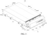
- the battery pack 100 is roughly a cuboid structure, a length direction of the battery pack 100 represents front-and-rear directions shown in FIG. 1 , a width direction of the battery pack 100 represents left-and-right directions shown in FIG. 1 , and a height direction of the battery pack 100 represents up-and-down directions shown in FIG. 1 .
- the battery pack 100 includes an enclosure 10, multiple cells, and a distribution box 30.
- the enclosure 10 includes a housing 11 and a cover body 12.
- the housing 11 is provided with a picking and placing opening 101 on a side of a length direction of the housing (front side shown in FIG. 3 ).
- Multiple chambers arranged in the width direction of the housing are defined in the housing 11.
- An opening 102 of each chamber faces the picking and placing opening 101, and the opening 102 of each chamber is in communication with the picking and placing opening 101, so that multiple cells are arranged in multiple chambers in a push-pull manner.
- the housing 11 includes multiple casings 111 arranged in left-and-right directions.
- a bottom wall of each casing 111 exceeds a top wall. Edges of bottom walls of the multiple casings 111 are flush, and edges of top walls of the multiple casings 111 are flush.
- Multiple partition plates 1111 arranged at intervals in left-and-right directions are arranged in each casing 111, so that an inner cavity of the casing 111 is divided into multiple chambers.
- Bottom walls of the two outermost casings 111 are respectively provided with triangular baffles 112 at the opening 102 of the chamber. Edges of the top wall and the bottom wall of each casing 111 close to the opening 102 of the chamber are respectively provided with multiple first connecting holes 1112 arranged at intervals.
- the front side edge of the baffle 112 is provided with a side flange 1121.
- the side flange 1121 is provided with multiple first connecting holes 1112 arranged at intervals.
- the cover body 12 includes a top plate 121, a first side plate 122, and two second side plates 123.
- the top plate 121 and the first side plate 122 are perpendicular to each other.
- An upper end of the first side plate 122 is connected to a front side edge of the top plate 121.
- the two second side plates 123 are arranged at the left and right ends of the top plate 121.
- Each second side plate 123 forms a right-angled triangular plate member.
- Upper edges of the two second side plates 123 are connected to the left and right ends of the top plate 121.
- a front side edges of the two second side plates 123 are connected to the left and right ends of the first side plate 122.
- a lower end of the first side plate 122 is provided with a first flange 1221.
- the front side edge of the second side plate 123 is provided with a second flange 1231.
- the top plate 121, the first flange 1221 of the first side plate 122, and the second flange 1231 of the second side plate 123 are respectively provided with multiple second connecting holes 1201 arranged at intervals.
- the first side plate 122 is provided with a port 1202 that runs through in a thickness direction of the first side plate.
- the distribution box 30 includes a metal plate 31, a low-voltage connector 32, and a high-voltage connector 33.
- the distribution box 30 is arranged in a position of the housing 11 close to the picking and placing opening 101.
- the metal plate 31 is connected to an edge of the port 1202 of the cover body 12 through a fastener, and the low-voltage connector 32 and the high-voltage connector 33 are respectively exposed out of the port 1202, thereby facilitating the connection with other components.
- the battery pack 100 is configured to be a cuboid structure, and a corresponding shielding structure is also the cuboid structure, thereby avoiding frequency resonance as much as possible.
- the radio frequency protection and shielding of signals of the battery pack 100 are ensured, the EMC interference is reduced, the signal transmission performance is enhanced, and the system safety and reliability are improved.
- the battery pack 100 has a simple structure, a regular shape, and a smaller volume, is convenient for spatial arrangement in the entire vehicle, and has higher adaptability.
- the vehicle 500 includes the battery pack 100 according to the foregoing embodiment.
- the vehicle 500 according to the embodiment of the present disclosure also has the foregoing technical effects. That is, by using the foregoing battery pack 100, the EMC interference is reduced, the signal transmission performance is enhanced, the system safety and reliability are improved, and it is beneficial for prolonging the service life of the vehicle 500.
- orientation or position relationships indicated by the terms such as “center”, “longitudinal”, “transverse”, “length”, “width”, “thickness”, “upper”, “lower”, “front”, “rear”, “left”, “right”, “vertical”, “horizontal”, “top”, “bottom”, “inner”, “outer”, “axial”, “radial”, and “circumferential” are based on orientation or position relationships shown in the accompanying drawings, and are used only for ease and brevity of illustration and description, rather than indicating or implying that the mentioned apparatus or component must has a particular orientation or must be constructed and operated in a particular orientation. Therefore, such terms should not be construed as a limitation on the present disclosure.
Landscapes
- Chemical & Material Sciences (AREA)
- Chemical Kinetics & Catalysis (AREA)
- Electrochemistry (AREA)
- General Chemical & Material Sciences (AREA)
- Engineering & Computer Science (AREA)
- Manufacturing & Machinery (AREA)
- Aviation & Aerospace Engineering (AREA)
- Inorganic Chemistry (AREA)
- Battery Mounting, Suspending (AREA)
- Secondary Cells (AREA)
Applications Claiming Priority (2)
| Application Number | Priority Date | Filing Date | Title |
|---|---|---|---|
| CN202110731924.9A CN115548546A (zh) | 2021-06-30 | 2021-06-30 | 电池包以及电动汽车 |
| PCT/CN2022/099542 WO2023273925A1 (fr) | 2021-06-30 | 2022-06-17 | Bloc-batterie et véhicule |
Publications (2)
| Publication Number | Publication Date |
|---|---|
| EP4300678A1 true EP4300678A1 (fr) | 2024-01-03 |
| EP4300678A4 EP4300678A4 (fr) | 2024-12-04 |
Family
ID=84690730
Family Applications (1)
| Application Number | Title | Priority Date | Filing Date |
|---|---|---|---|
| EP22831743.4A Pending EP4300678A4 (fr) | 2021-06-30 | 2022-06-17 | Bloc-batterie et véhicule |
Country Status (7)
| Country | Link |
|---|---|
| US (1) | US20240030530A1 (fr) |
| EP (1) | EP4300678A4 (fr) |
| JP (1) | JP2024518016A (fr) |
| KR (1) | KR20230148841A (fr) |
| CN (1) | CN115548546A (fr) |
| CA (1) | CA3213965A1 (fr) |
| WO (1) | WO2023273925A1 (fr) |
Families Citing this family (3)
| Publication number | Priority date | Publication date | Assignee | Title |
|---|---|---|---|---|
| USD1101671S1 (en) * | 2022-09-08 | 2025-11-11 | Harbinger Motors Inc. | Battery pack |
| USD1083781S1 (en) * | 2023-02-27 | 2025-07-15 | Huizhou Roypow Technology Co., Ltd | Battery pack |
| CN219717145U (zh) * | 2023-04-20 | 2023-09-19 | 惠州亿纬锂能股份有限公司 | 电池包上盖、电池包以及车辆 |
Family Cites Families (21)
| Publication number | Priority date | Publication date | Assignee | Title |
|---|---|---|---|---|
| JPH07106014B2 (ja) * | 1988-09-02 | 1995-11-13 | 矢崎総業株式会社 | 電気接続箱 |
| JP5099985B2 (ja) * | 2005-06-29 | 2012-12-19 | 三洋電機株式会社 | パック電池 |
| JP4915061B2 (ja) * | 2005-08-08 | 2012-04-11 | トヨタ自動車株式会社 | 電源パック構造 |
| JP5850689B2 (ja) * | 2011-09-29 | 2016-02-03 | 株式会社イノアックコーポレーション | 車両用電磁波シールドカバー |
| CN202721200U (zh) * | 2012-04-19 | 2013-02-06 | 赵军辉 | 锂电池的塑料金属复合外壳 |
| JP2014003846A (ja) * | 2012-06-20 | 2014-01-09 | Cotac Co Ltd | ポータブル電源システム及びポータブル電源装置 |
| CN204361724U (zh) * | 2014-12-30 | 2015-05-27 | 比亚迪股份有限公司 | 电池系统和用于电池系统的配电盒 |
| EP3579297A4 (fr) * | 2017-02-06 | 2020-12-02 | Vehicle Energy Japan Inc. | Bloc d'éléments |
| CN206497928U (zh) * | 2017-03-10 | 2017-09-15 | 江苏索尔新能源科技股份有限公司 | 一种用于新能源汽车的电池组件 |
| JP7166812B2 (ja) * | 2017-07-05 | 2022-11-08 | 株式会社イノアックコーポレーション | 車両用バッテリーケース |
| KR102354401B1 (ko) * | 2018-04-25 | 2022-01-20 | 주식회사 엘지에너지솔루션 | 배터리 모듈 및 이를 포함하는 배터리 팩 |
| CN111129376A (zh) * | 2018-10-31 | 2020-05-08 | 王海林 | 一种用于电动车辆的新型驱动电池箱 |
| CN111192983B (zh) * | 2018-11-15 | 2024-09-10 | 宁德时代新能源科技股份有限公司 | 电池包 |
| JP7133702B2 (ja) * | 2019-02-27 | 2022-09-08 | 本田技研工業株式会社 | エンドプレートの固定構造及びバッテリ装置 |
| CN110190202A (zh) * | 2019-05-13 | 2019-08-30 | 北京长城华冠汽车科技股份有限公司 | 车用蓄电池和车辆 |
| CN210006806U (zh) * | 2019-08-29 | 2020-01-31 | 蜂巢能源科技有限公司 | 电池包的壳体、电池包和车辆 |
| JP2021072176A (ja) * | 2019-10-29 | 2021-05-06 | 三菱自動車工業株式会社 | 車両用電池パック |
| CN211605270U (zh) * | 2020-04-03 | 2020-09-29 | 上海派能能源科技股份有限公司 | 一种电池模组及堆叠电池组 |
| CN213026368U (zh) * | 2020-09-02 | 2021-04-20 | 比亚迪股份有限公司 | 电池模组 |
| CN213304255U (zh) * | 2020-11-11 | 2021-05-28 | 益高电动车辆制造(毕节市)有限公司 | 电池箱 |
| CN213520149U (zh) * | 2020-11-27 | 2021-06-22 | 蜂巢能源科技有限公司 | 电池包结构及电动汽车 |
-
2021
- 2021-06-30 CN CN202110731924.9A patent/CN115548546A/zh active Pending
-
2022
- 2022-06-17 KR KR1020237032487A patent/KR20230148841A/ko not_active Ceased
- 2022-06-17 JP JP2023555492A patent/JP2024518016A/ja active Pending
- 2022-06-17 CA CA3213965A patent/CA3213965A1/fr active Pending
- 2022-06-17 EP EP22831743.4A patent/EP4300678A4/fr active Pending
- 2022-06-17 WO PCT/CN2022/099542 patent/WO2023273925A1/fr not_active Ceased
-
2023
- 2023-09-27 US US18/373,850 patent/US20240030530A1/en active Pending
Also Published As
| Publication number | Publication date |
|---|---|
| CA3213965A1 (fr) | 2023-01-05 |
| US20240030530A1 (en) | 2024-01-25 |
| WO2023273925A1 (fr) | 2023-01-05 |
| EP4300678A4 (fr) | 2024-12-04 |
| JP2024518016A (ja) | 2024-04-24 |
| KR20230148841A (ko) | 2023-10-25 |
| CN115548546A (zh) | 2022-12-30 |
Similar Documents
| Publication | Publication Date | Title |
|---|---|---|
| US20240030530A1 (en) | Battery pack and vehicle | |
| US20210249725A1 (en) | Battery pack, vehicle, and energy storage device | |
| CN217507468U (zh) | 电池模组 | |
| EP4589729A1 (fr) | Bloc-batterie et dispositif électrique | |
| KR102882505B1 (ko) | 배터리 모듈 | |
| CN211980690U (zh) | 一种液冷集成电池箱体 | |
| CN217691353U (zh) | 电池包和储能系统 | |
| WO2025200116A1 (fr) | Batterie et véhicule | |
| CN115911652A (zh) | 一种刀片铝壳电池模组 | |
| CN209151462U (zh) | 一体化设计的tr组件的壳体 | |
| CN113036276B (zh) | 电池包和电动车 | |
| EP4561275A1 (fr) | Boîtier de dispositif de commande, dispositif de commande central et automobile | |
| CN119786852B (zh) | 电池包、电池包的制造方法和用电设备 | |
| CN221327934U (zh) | 电池包箱体和电池包 | |
| CN116387742A (zh) | 一种箱体、电池包、电池簇及储能设备 | |
| CN213818658U (zh) | 液冷机箱 | |
| CN221727228U (zh) | 一种具有散热机构的电池防护箱 | |
| CN219575740U (zh) | 一种储能锂电池防过热冷却装置 | |
| CN222374752U (zh) | 机架以及真空镀膜设备 | |
| CN216626467U (zh) | 一种强制风冷散热防水机箱 | |
| CN223714435U (zh) | 散热结构、滤波装置及储能设备 | |
| CN221262614U (zh) | 一种电池模组单元结构 | |
| CN223462294U (zh) | 一种液冷组件、电池模组以及电池包 | |
| CN221598344U (zh) | 一种无人机飞控箱体 | |
| CN223427347U (zh) | 固态变压器 |
Legal Events
| Date | Code | Title | Description |
|---|---|---|---|
| STAA | Information on the status of an ep patent application or granted ep patent |
Free format text: STATUS: THE INTERNATIONAL PUBLICATION HAS BEEN MADE |
|
| PUAI | Public reference made under article 153(3) epc to a published international application that has entered the european phase |
Free format text: ORIGINAL CODE: 0009012 |
|
| STAA | Information on the status of an ep patent application or granted ep patent |
Free format text: STATUS: REQUEST FOR EXAMINATION WAS MADE |
|
| 17P | Request for examination filed |
Effective date: 20230927 |
|
| AK | Designated contracting states |
Kind code of ref document: A1 Designated state(s): AL AT BE BG CH CY CZ DE DK EE ES FI FR GB GR HR HU IE IS IT LI LT LU LV MC MK MT NL NO PL PT RO RS SE SI SK SM TR |
|
| DAV | Request for validation of the european patent (deleted) | ||
| DAX | Request for extension of the european patent (deleted) | ||
| A4 | Supplementary search report drawn up and despatched |
Effective date: 20241106 |
|
| RIC1 | Information provided on ipc code assigned before grant |
Ipc: H01M 10/6554 20140101ALI20241030BHEP Ipc: H01M 50/249 20210101ALI20241030BHEP Ipc: H01M 50/209 20210101ALI20241030BHEP Ipc: H01M 50/244 20210101ALI20241030BHEP Ipc: H01M 50/258 20210101ALI20241030BHEP Ipc: H01M 50/271 20210101ALI20241030BHEP Ipc: H01M 50/289 20210101ALI20241030BHEP Ipc: H01M 50/204 20210101AFI20241030BHEP |