EP4300864A1 - Kommunikationsverfahren und kommunikationsvorrichtung - Google Patents
Kommunikationsverfahren und kommunikationsvorrichtung Download PDFInfo
- Publication number
- EP4300864A1 EP4300864A1 EP22779164.7A EP22779164A EP4300864A1 EP 4300864 A1 EP4300864 A1 EP 4300864A1 EP 22779164 A EP22779164 A EP 22779164A EP 4300864 A1 EP4300864 A1 EP 4300864A1
- Authority
- EP
- European Patent Office
- Prior art keywords
- ssb
- coreset
- rbs
- spacing
- value
- Prior art date
- Legal status (The legal status is an assumption and is not a legal conclusion. Google has not performed a legal analysis and makes no representation as to the accuracy of the status listed.)
- Pending
Links
- 238000000034 method Methods 0.000 title claims abstract description 181
- 238000004891 communication Methods 0.000 title claims abstract description 106
- 230000005540 biological transmission Effects 0.000 claims abstract description 25
- 238000004590 computer program Methods 0.000 claims description 48
- 230000011664 signaling Effects 0.000 claims description 19
- 235000019527 sweetened beverage Nutrition 0.000 description 581
- 230000006870 function Effects 0.000 description 46
- 101100096715 Bacillus anthracis ssb gene Proteins 0.000 description 23
- 238000010586 diagram Methods 0.000 description 21
- 108010014173 Factor X Proteins 0.000 description 12
- 238000005516 engineering process Methods 0.000 description 9
- 230000000694 effects Effects 0.000 description 7
- 230000006399 behavior Effects 0.000 description 6
- 238000010295 mobile communication Methods 0.000 description 6
- 230000003287 optical effect Effects 0.000 description 3
- 230000003190 augmentative effect Effects 0.000 description 2
- 238000004364 calculation method Methods 0.000 description 2
- 230000008878 coupling Effects 0.000 description 2
- 238000010168 coupling process Methods 0.000 description 2
- 238000005859 coupling reaction Methods 0.000 description 2
- 238000001514 detection method Methods 0.000 description 2
- 230000007774 longterm Effects 0.000 description 2
- 238000007726 management method Methods 0.000 description 2
- 239000007787 solid Substances 0.000 description 2
- 101150069124 RAN1 gene Proteins 0.000 description 1
- 101100355633 Salmo salar ran gene Proteins 0.000 description 1
- 238000004422 calculation algorithm Methods 0.000 description 1
- FFGPTBGBLSHEPO-UHFFFAOYSA-N carbamazepine Chemical compound C1=CC2=CC=CC=C2N(C(=O)N)C2=CC=CC=C21 FFGPTBGBLSHEPO-UHFFFAOYSA-N 0.000 description 1
- 238000013500 data storage Methods 0.000 description 1
- 239000004065 semiconductor Substances 0.000 description 1
Images




Classifications
-
- H—ELECTRICITY
- H04—ELECTRIC COMMUNICATION TECHNIQUE
- H04W—WIRELESS COMMUNICATION NETWORKS
- H04W16/00—Network planning, e.g. coverage or traffic planning tools; Network deployment, e.g. resource partitioning or cells structures
- H04W16/14—Spectrum sharing arrangements between different networks
-
- H—ELECTRICITY
- H04—ELECTRIC COMMUNICATION TECHNIQUE
- H04L—TRANSMISSION OF DIGITAL INFORMATION, e.g. TELEGRAPHIC COMMUNICATION
- H04L5/00—Arrangements affording multiple use of the transmission path
- H04L5/003—Arrangements for allocating sub-channels of the transmission path
- H04L5/0048—Allocation of pilot signals, i.e. of signals known to the receiver
-
- H—ELECTRICITY
- H04—ELECTRIC COMMUNICATION TECHNIQUE
- H04L—TRANSMISSION OF DIGITAL INFORMATION, e.g. TELEGRAPHIC COMMUNICATION
- H04L27/00—Modulated-carrier systems
- H04L27/0006—Assessment of spectral gaps suitable for allocating digitally modulated signals, e.g. for carrier allocation in cognitive radio
-
- H—ELECTRICITY
- H04—ELECTRIC COMMUNICATION TECHNIQUE
- H04L—TRANSMISSION OF DIGITAL INFORMATION, e.g. TELEGRAPHIC COMMUNICATION
- H04L5/00—Arrangements affording multiple use of the transmission path
- H04L5/0001—Arrangements for dividing the transmission path
- H04L5/0003—Two-dimensional division
- H04L5/0005—Time-frequency
- H04L5/0007—Time-frequency the frequencies being orthogonal, e.g. OFDM(A) or DMT
-
- H—ELECTRICITY
- H04—ELECTRIC COMMUNICATION TECHNIQUE
- H04L—TRANSMISSION OF DIGITAL INFORMATION, e.g. TELEGRAPHIC COMMUNICATION
- H04L5/00—Arrangements affording multiple use of the transmission path
- H04L5/0001—Arrangements for dividing the transmission path
- H04L5/0014—Three-dimensional division
- H04L5/0023—Time-frequency-space
-
- H—ELECTRICITY
- H04—ELECTRIC COMMUNICATION TECHNIQUE
- H04L—TRANSMISSION OF DIGITAL INFORMATION, e.g. TELEGRAPHIC COMMUNICATION
- H04L5/00—Arrangements affording multiple use of the transmission path
- H04L5/003—Arrangements for allocating sub-channels of the transmission path
- H04L5/0053—Allocation of signalling, i.e. of overhead other than pilot signals
-
- H—ELECTRICITY
- H04—ELECTRIC COMMUNICATION TECHNIQUE
- H04W—WIRELESS COMMUNICATION NETWORKS
- H04W48/00—Access restriction; Network selection; Access point selection
- H04W48/08—Access restriction or access information delivery, e.g. discovery data delivery
- H04W48/10—Access restriction or access information delivery, e.g. discovery data delivery using broadcasted information
-
- H—ELECTRICITY
- H04—ELECTRIC COMMUNICATION TECHNIQUE
- H04W—WIRELESS COMMUNICATION NETWORKS
- H04W48/00—Access restriction; Network selection; Access point selection
- H04W48/16—Discovering, processing access restriction or access information
-
- H—ELECTRICITY
- H04—ELECTRIC COMMUNICATION TECHNIQUE
- H04W—WIRELESS COMMUNICATION NETWORKS
- H04W74/00—Wireless channel access
- H04W74/08—Non-scheduled access, e.g. ALOHA
- H04W74/0808—Non-scheduled access, e.g. ALOHA using carrier sensing, e.g. carrier sense multiple access [CSMA]
Definitions
- This application relates to the communication field, and in particular, to a communication method and apparatus.
- a receiving device for example, user equipment (user equipment, UE) that accesses different types of bands first detects a synchronization signal block pattern (synchronization signal block pattern, SS/PBCH Block/SSB) sent by a base station.
- the SSB includes a physical broadcast channel (physical broadcast channel, PBCH) carrying master information block (master information block, MIB) information.
- master information block, MIB master information block
- a same parameter in the MIB information represents different content on a licensed band and a shared band.
- the base station cannot send a specified SSB at a specified position due to existence of a listen before talk (listen before talk, LBT) mechanism. Therefore, a Q value (namely, N SSB QCL ) is defined.
- the UE may calculate, by demodulating the Q value and based on a demodulation reference signal (demodulation reference signal, DMRS) sequence, a plurality of candidate positions for sending a same SSB index.
- DMRS demodulation reference signal
- DBTW discovery burst transmission window
- This application provides a communication method and apparatus, so that a terminal device can determine a status of a DBTW, to quickly implement timing synchronization with a network device.
- a communication method is provided.
- the method is applied to an unlicensed band.
- An execution body of the method may be a terminal device, or may be a chip used in a terminal device. The following provides descriptions by using an example in which the execution body is the terminal device.
- the terminal device receives first information sent by a network device, where the first information includes a Q value or a first parameter, and the first parameter indicates a status of a discovery burst transmission window DBTW; and determines the status of the DBTW based on the Q value or the first parameter.
- the terminal device can determine the status of the DBTW based on the first information sent by the network device, therefore can determine whether the network device sends, within the DBTW, an SSB that cannot be sent due to an LBT failure, and further, can quickly implement timing synchronization with the network device.
- the determining the status of the DBTW based on the Q value includes:
- the determining the status of the DBTW based on a DBTW value includes:
- the terminal device determines the status of the DBTW based on a value relationship between the Q value and the first threshold. If the status of the DBTW cannot be determined, the terminal device can further determine the status of the DBTW based on the DBTW value. In this way, it can be determined whether the network device sends, within the DBTW, the SSB that cannot be sent due to the LBT failure, to quickly implement timing synchronization with the network device.
- the second threshold is time duration from a 1 st symbol in a slot in which a first synchronization signal block SSB is located to a last symbol in a slot in which a second SSB is located.
- An index of the first SSB is 0, and an index of the second SSB is (Q-1).
- the second threshold is time duration from a 1 st symbol in a slot in which a third SSB is located to a last symbol in a slot in which a fourth SSB is located.
- the third SSB is located in a first SSB group
- the fourth SSB is located in a second SSB group.
- the first SSB group is a 1 st group whose bit is configured as "1" from the left in a second parameter.
- the second SSB group is a 1 st group whose bit is configured as "1" from the right in the second parameter.
- the second threshold is time duration from a 1 st symbol in a slot in which a fifth SSB is located to a last symbol in a slot in which a sixth SSB is located.
- the fifth SSB is an SSB with a smallest index in successfully sent SSBs
- the sixth SSB is an SSB with a largest index in the successfully sent SSBs.
- the second threshold is time duration from a slot in which a first SSB is located to a slot in which a second SSB is located.
- An index of the first SSB is 0, and an index of the second SSB is (Q-1).
- the second threshold is time duration from a slot in which a third SSB is located to a slot in which a fourth SSB is located.
- the third SSB is located in a first SSB group
- the fourth SSB is located in a second SSB group.
- the first SSB group is a 1 st group whose bit is configured as "1" from the left in a second parameter.
- the second SSB group is a 1 st group whose bit is configured as "1" from the right in the second parameter.
- the second threshold is time duration from a slot in which a fifth SSB is located to a slot in which a sixth SSB is located.
- the fifth SSB is an SSB with a smallest index in successfully sent SSBs
- the sixth SSB is an SSB with a largest index in the successfully sent SSBs.
- the second threshold is time duration from a 1 st symbol index of a first SSB to a last symbol index of a second SSB.
- An index of the first SSB is 0, and an index of the second SSB is (Q-1).
- the second threshold is time duration from a 1 st symbol index of a third SSB to a last symbol index of a fourth SSB.
- the third SSB is located in a first SSB group
- the fourth SSB is located in a second SSB group.
- the first SSB group is a 1 st group whose bit is configured as "1" from the left in a second parameter.
- the second SSB group is a 1 st group whose bit is configured as "1" from the right in the second parameter.
- the second threshold is time duration from a 1 st symbol index of a fifth SSB to a last symbol index of a sixth SSB.
- the fifth SSB is an SSB with a smallest index in successfully sent SSBs
- the sixth SSB is an SSB with a largest index in the successfully sent SSBs.
- the Q value is indicated by using n bits, and n is a positive integer greater than 2.
- the n bits include at least one bit indicating a third parameter.
- the third parameter includes at least one of the following parameters: subcarrier spacing common in master information block MIB information, an SSB-subcarrier offset in the MIB information, and a physical downlink control channel-configuration system information block 1 PDCCH-configuration SIB 1 in the MIB information.
- the Q value can be indicated by using the n bits, and the n bits include the at least one bit indicating the third parameter.
- the bits indicating the Q value can be a corresponding bit of another parameter in the MIB. This can improve system performance.
- the PDCCH-configuration SIB 1 includes search space zero and a control resource set zero.
- the n bits include n1 bits indicating a fourth parameter and (n-n1) bits indicating a fifth parameter.
- the fourth parameter is any parameter in the third parameter
- the fifth parameter is a parameter in the third parameter other than the fourth parameter.
- the fifth parameter is indicated by using m-(n-n1) bits, and m is an initial number indicating the fifth parameter.
- the Q value used to determine the status of the DBTW can be indicated by using the n bits.
- the n bits include the n1 bits indicating the fourth parameter and the (n-n1) bits indicating the fifth parameter.
- the fifth parameter is indicated by using the m-(n-n1) bits, and m is the initial number indicating the fifth parameter.
- the Q value can be indicated by using the corresponding bit of the another parameter in the MIB. This can avoid indicating the Q value by expanding the MIB payload capacity, thereby improving system performance.
- the n bits include n1 bits indicating a fourth parameter and (n-n1) bits indicating a fifth parameter.
- the fourth parameter is any parameter in the third parameter
- the fifth parameter is a parameter in the third parameter other than the fourth parameter.
- the fifth parameter is indicated by using m bits, m is an initial number indicating the fifth parameter, and (n-n1) ⁇ m.
- the Q value used to determine the status of the DBTW can be indicated by using the n bits.
- the n bits include the n1 bits indicating the fourth parameter and the (n-n1) bits indicating the fifth parameter.
- the fifth parameter is indicated by using the m bits.
- the Q value can be indicated by using the corresponding bit of the another parameter in the MIB. This can avoid indicating the Q value by expanding the MIB payload capacity, and does not affect bit indication of the fifth parameter, thereby improving system performance.
- the fifth parameter is the SSB-subcarrier offset in the MIB information.
- An offset value of the SSB-subcarrier offset is determined based on a combination of a subcarrier spacing SCS of the SSB and an SCS of a common resource block CRB.
- the offset value of the SSB-subcarrier offset is determined based on a preset threshold.
- the offset value of the SSB-subcarrier offset is a value indicated by the (n-n1) bits indicating the fifth parameter.
- the offset value of the SSB-subcarrier offset is less than or equal to a value indicated by the (n-n1) bits of the fifth parameter.
- the (n-n1) bits are (n-n1) most significant bits in the fifth parameter.
- the (n-n1) bits are (n-n1) least significant bits in the fifth parameter.
- the (n-n1) bits are any (n-n1) bits in the fifth parameter.
- the determining the status of the DBTW based on the first parameter includes:
- the terminal device can determine the status of the DBTW based on the first parameter sent by the network device, therefore can determine whether the network device sends, within the DBTW, an SSB that cannot be sent due to an LBT failure, and further, can quickly implement timing synchronization with the network device.
- the first parameter is carried in serving cell configuration common in radio resource control RRC signaling or a serving cell configuration common SIB in SIB 1 information.
- the Q value or the DBTW value is carried in serving cell configuration common or a serving cell configuration common SIB.
- the PDCCH-configuration SIB 1 includes the search space zero and the control resource set zero.
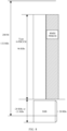
- the control resource set zero includes a number of resource blocks RBs occupied by the control resource set CORESET #0, and the number of RBs is 96.
- a first spacing included in the control resource set zero is any value of 0 to (96-k).
- the first spacing indicates a spacing between an RB with a smallest index in the SSB and an RB with a smallest index in the CORESET #0.
- a first spacing is determined based on a value of an offset between the SSB and a subcarrier in the CRB.
- the pattern of multiplexing the SSB and the CORESET #0 is 2 or 3
- a number of symbols occupied by the CORESET #0 is any value of 1 to 4.
- a number of symbols occupied by the CORESET #0 is 1 or 2.
- a number of symbols occupied by the CORESET #0 is 1 or 2.
- a communication method is provided.
- the method is applied to an unlicensed band.
- An execution body of the method may be a network device, or may be a chip used in a network device. The following provides descriptions by using an example in which the execution body is the network device.
- the network device determines first information.
- the first information includes a Q value or a first parameter.
- the first parameter indicates a status of a discovery burst transmission window DBTW.
- the network device sends the first information to a terminal device.
- the network device can send the first information to the terminal device, so that the terminal device determines the status of the DBTW, and the terminal device determines whether the network device sends, within the DBTW, an SSB that cannot be sent due to an LBT failure. Further, the terminal device can quickly implement timing synchronization with the network device.
- the Q value is indicated by using n bits, and n is a positive integer greater than 2.
- the n bits include at least one bit indicating a third parameter.
- the third parameter includes at least one of the following parameters: subcarrier spacing common in master information block MIB information, a synchronization signal block SSB-subcarrier offset in the MIB information, and a physical downlink control channel-configuration system information block 1 PDCCH-configuration SIB 1 in the MIB information.
- the Q value can be indicated by using the n bits, and the n bits include the at least one bit indicating the third parameter.
- the bits indicating the Q value can be a corresponding bit of another parameter in the MIB. This can improve system performance.
- the PDCCH-configuration SIB 1 includes search space zero and a control resource set zero.
- the n bits include n1 bits indicating a fourth parameter and (n-n1) bits indicating a fifth parameter.
- the fourth parameter is any parameter in the third parameter
- the fifth parameter is a parameter in the third parameter other than the fourth parameter.
- the fifth parameter is indicated by using m-(n-n1) bits, and m is an initial number indicating the fifth parameter.
- the Q value used to determine the status of the DBTW can be indicated by using the n bits.
- the n bits include the n1 bits indicating the fourth parameter and the (n-n1) bits indicating the fifth parameter.
- the fifth parameter is indicated by using the m-(n-n1) bits, and m is the initial number indicating the fifth parameter.
- the Q value can be indicated by using the corresponding bit of the another parameter in the MIB. This can avoid indicating the Q value by expanding the MIB payload capacity, thereby improving system performance.
- the n bits include n1 bits indicating a fourth parameter and (n-n1) bits indicating a fifth parameter.
- the fourth parameter is any parameter in the third parameter
- the fifth parameter is a parameter in the third parameter other than the fourth parameter.
- the fifth parameter is indicated by using m bits, m is an initial number indicating the fifth parameter, and (n-n1) ⁇ m.
- the Q value used to determine the status of the DBTW can be indicated by using the n bits.
- the n bits include the n1 bits indicating the fourth parameter and the (n-n1) bits indicating the fifth parameter.
- the fifth parameter is indicated by using the m bits.
- the Q value can be indicated by using the corresponding bit of the another parameter in the MIB. This can avoid indicating the Q value by expanding the MIB payload capacity, and does not affect bit indication of the fifth parameter, thereby improving system performance.
- the fifth parameter is the SSB-subcarrier offset in the MIB information.
- An offset value of the SSB-subcarrier offset is determined based on a combination of a subcarrier spacing SCS of the SSB and an SCS of a common resource block CRB.
- the offset value of the SSB-subcarrier offset is determined based on a preset threshold.
- the offset value of the SSB-subcarrier offset is a value indicated by the (n-n1) bits of the fifth parameter.
- the offset value of the SSB-subcarrier offset is less than or equal to a value indicated by the (n-n1) bits of the fifth parameter.
- the (n-n1) bits are (n-n1) most significant bits in the fifth parameter.
- the (n-n1) bits are (n-n1) least significant bits in the fifth parameter.
- the (n-n1) bits are any (n-n1) bits in the fifth parameter.
- the first parameter is carried in serving cell configuration common in radio resource control RRC signaling or a serving cell configuration common SIB in SIB 1 information.
- the Q value or a DBTW value is carried in serving cell configuration common or a serving cell configuration common SIB.
- the PDCCH-configuration SIB 1 includes the search space zero and the control resource set zero.
- the control resource set zero includes a number of resource blocks RBs occupied by the control resource set CORESET #0, and the number of RBs is 96.
- a first spacing included in the control resource set zero is any value of 0 to (96-k).
- the first spacing indicates a spacing between an RB with a smallest index in the SSB and an RB with a smallest index in the CORESET #0.
- a first spacing is determined based on a value of an offset between the SSB and a subcarrier in the CRB.
- the pattern of multiplexing the SSB and the CORESET #0 is 2 or 3
- a number of symbols occupied by the CORESET #0 is any value of 1 to 4.
- a number of symbols occupied by the CORESET #0 is 2.
- a number of symbols occupied by the CORESET #0 is 1 or 2.
- An execution body of the method may be a terminal device, or may be a chip used in a terminal device.
- the following provides descriptions by using an example in which the execution body is the terminal device.
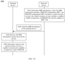
- the terminal device receives master information block MIB information sent by a network device.
- the MIB information includes a physical downlink control channel-configuration system information block 1 PDCCH-configuration SIB 1.
- the PDCCH-configuration SIB 1 includes a control resource set zero.
- the control resource set zero includes a number of resource blocks RBs occupied by the control resource set CORESET #0, and the number of RBs is 96.
- the terminal device determines, based on the control resource set zero, a number of consecutive symbols occupied by a type 0-physical downlink control channel type 0-PDCCH.
- the network device sends the MIB information to the terminal device.
- the MIB includes the parameter control resource set zero.
- the number, that is included in the control resource set zero, of RBs occupied by the CORESET #0 is 96.
- the terminal device can determine, based on the received control resource set zero, the number of consecutive symbols occupied by the type 0-PDCCH.
- a first spacing included in the control resource set zero is any value of 0 to (96-k).
- the first spacing indicates a spacing between an RB with a smallest index in the SSB and an RB with a smallest index in the CORESET #0.
- a first spacing is determined based on a value of an offset between the SSB and a subcarrier in a CRB.
- the pattern of multiplexing the SSB and the CORESET #0 is 2 or 3
- a number of symbols occupied by the CORESET #0 is any value of 1 to 4.
- a number of symbols occupied by the CORESET #0 is 2.
- a number of symbols occupied by the CORESET #0 is 1 or 2.
- An execution body of the method may be a network device, or may be a chip used in a network device.
- the following provides descriptions by using an example in which the execution body is the network device.
- the network device determines master information block MIB information.
- the MIB information includes a physical downlink control channel-configuration system information block 1 PDCCH-configuration SIB 1.
- the PDCCH-configuration SIB 1 includes a control resource set zero.
- the control resource set zero includes a number of resource blocks RBs occupied by the control resource set CORESET #0, and the number of RBs is 96.
- the network device sends the MIB information to a terminal device.
- the network device sends the MIB information to the terminal device.
- the MIB includes the parameter control resource set zero.
- the number, that is included in the control resource set zero, of RBs occupied by the CORESET #0 is 96.
- the terminal device can determine, based on the received control resource set zero, a number of consecutive symbols occupied by a type 0-PDCCH.
- a first spacing included in the control resource set zero is any value of 0 to (96-k).
- the first spacing indicates a spacing between an RB with a smallest index in the SSB and an RB with a smallest index in the CORESET #0.
- a first spacing is determined based on a value of an offset between the SSB and a subcarrier in a CRB.
- the pattern of multiplexing the SSB and the CORESET #0 is 2 or 3
- a number of symbols occupied by the CORESET #0 is any value of 1 to 4.
- a number of symbols occupied by the CORESET #0 is 2.
- a number of symbols occupied by the CORESET #0 is 1 or 2.
- a communication method is provided.
- the method is applied to a licensed band.
- An execution body of the method may be a terminal device, or may be a chip used in a terminal device. The following provides descriptions by using an example in which the execution body is the terminal device.
- the terminal device receives MIB information sent by a network device.
- the MIB information includes subcarrier spacing common.
- the subcarrier spacing common is indicated by using r bits, and r is a positive integer greater than or equal to 2.
- the terminal device performs timing synchronization based on the MIB information.
- the network device sends the MIB information to the terminal device.
- the MIB includes the subcarrier spacing common, and the subcarrier spacing common is indicated by using at least two bits.
- the terminal device After receiving the MIB information, the terminal device can perform timing synchronization based on the received MIB information.
- the r bits include one initial bit indicating the subcarrier spacing common and (r-1) bits indicating a sixth parameter.
- the sixth parameter includes at least one of the following parameters: an SSB-subcarrier offset in the MIB information and a PDCCH-configuration SIB 1 in the MIB information.
- the PDCCH-configuration SIB 1 includes search space zero and a control resource set zero.
- the r bits include the initial bit indicating the subcarrier spacing common and the (r-1) bits indicating a seventh parameter.
- the seventh parameter is any parameter in the sixth parameter, the seventh parameter is indicated by using (s-(r-1)) bits, and s is an initial number indicating the seventh parameter.
- the subcarrier spacing common in the MIB information can be indicated by using the r bits.
- the r bits include the initial bit indicating the subcarrier spacing common and the (r-1) bits indicating the seventh parameter.
- the seventh parameter is indicated by using the (s-(r-1)) bits, and s is the initial number indicating the seventh parameter.
- the subcarrier spacing common can be indicated by using a corresponding bit of another parameter in the MIB. This can avoid indicating the subcarrier spacing common by expanding a MIB load capacity, thereby improving system performance.
- the r bits include the initial bit indicating the subcarrier spacing common and the (r-1) bits indicating a seventh parameter.
- the seventh parameter is any parameter in the sixth parameter, the seventh parameter is indicated by using s bits, and s is an initial number indicating the seventh parameter.
- the subcarrier spacing common in the MIB information can be indicated by using the r bits.
- the r bits include the initial bit indicating the subcarrier spacing common and the (r-1) bits indicating the seventh parameter.
- the seventh parameter is indicated by using the s bits.
- the subcarrier spacing common can be indicated by using a corresponding bit of another parameter in the MIB. This can avoid indicating the subcarrier spacing common by expanding a MIB load capacity, and does not affect bit indication of the seventh parameter, thereby improving system performance.
- the seventh parameter is the SSB-subcarrier offset in the MIB information.
- a value of the SSB-subcarrier offset is determined based on a combination of an SCS of an SSB and an SCS of a CRB.
- the value of the SSB-subcarrier offset is determined based on a preset threshold.
- the value of the SSB-subcarrier offset is a value indicated by the (r-1) bits of the seventh parameter.
- the value of the SSB-subcarrier offset is less than or equal to a value indicated by the (r-1) bits of the seventh parameter.
- a communication method is provided.
- the method is applied to a licensed band.
- An execution body of the method may be a network device, or may be a chip used in a network device. The following provides descriptions by using an example in which the execution body is the network device.
- the network device determines MIB information.
- the MIB information includes first subcarrier spacing common.
- the first subcarrier spacing common is indicated by using r bits, and r is a positive integer greater than or equal to 2.
- the network device sends the MIB information to a terminal device.
- the network device sends the MIB information to the terminal device.
- the MIB includes the subcarrier spacing common, and the subcarrier spacing common is indicated by using at least two bits.
- the terminal device can perform timing synchronization based on the received MIB information.
- the r bits include one initial bit indicating the subcarrier spacing common and (r-1) bits indicating a sixth parameter.
- the sixth parameter includes at least one of the following parameters: an SSB-subcarrier offset in the MIB information and a PDCCH-configuration SIB 1 in the MIB information.
- the PDCCH-configuration SIB 1 includes search space zero and a control resource set zero.
- the r bits include the initial bit indicating the subcarrier spacing common and the (r-1) bits indicating a seventh parameter.
- the seventh parameter is any parameter in the sixth parameter, the seventh parameter is indicated by using (s-(r-1)) bits, and s is an initial number indicating the seventh parameter.
- the subcarrier spacing common in the MIB information can be indicated by using the r bits.
- the r bits include the initial bit indicating the subcarrier spacing common and the (r-1) bits indicating the seventh parameter.
- the seventh parameter is indicated by using the (s-(r-1)) bits, and s is the initial number indicating the seventh parameter.
- the subcarrier spacing common can be indicated by using a corresponding bit of another parameter in the MIB. This can avoid indicating the subcarrier spacing common by expanding a MIB load capacity, thereby improving system performance.
- the r bits include the initial bit indicating the subcarrier spacing common and the (r-1) bits indicating a seventh parameter.
- the seventh parameter is any parameter in the sixth parameter, the seventh parameter is indicated by using s bits, and s is an initial number indicating the seventh parameter.
- the subcarrier spacing common in the MIB information can be indicated by using the r bits.
- the r bits include the initial bit indicating the subcarrier spacing common and the (r-1) bits indicating the seventh parameter.
- the seventh parameter is indicated by using the s bits.
- the subcarrier spacing common can be indicated by using a corresponding bit of another parameter in the MIB. This can avoid indicating the subcarrier spacing common by expanding a MIB load capacity, and does not affect bit indication of the seventh parameter, thereby improving system performance.
- the seventh parameter is the SSB-subcarrier offset in the MIB information.
- a value of the SSB-subcarrier offset is determined based on a combination of an SCS of an SSB and an SCS of a CRB.
- the value of the SSB-subcarrier offset is determined based on a preset threshold.
- the value of the SSB-subcarrier offset is a value indicated by the (r-1) bits of the seventh parameter.
- the value of the SSB-subcarrier offset is less than or equal to a value indicated by the (r-1) bits of the seventh parameter.
- a communication apparatus has functions of implementing behavior in the method embodiment in the first aspect.
- the function may be implemented by hardware, or may be implemented by hardware executing corresponding software.
- the hardware includes one or more modules corresponding to the foregoing functions.
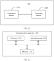
- the communication apparatus includes: a transceiver module, configured to receive first information sent by a network device, where the first information includes a Q value or a first parameter, and the first parameter indicates a status of a discovery burst transmission window DBTW; and a processing module, configured to determine the status of the DBTW based on the Q value or the first parameter.
- These modules may perform corresponding functions in the method example in the first aspect. For details, refer to the detailed descriptions in the method example. Details are not described herein again.
- a communication apparatus has functions of implementing behavior in the method example in the second aspect.
- the function may be implemented by hardware, or may be implemented by hardware executing corresponding software.
- the hardware or the software includes one or more modules corresponding to the foregoing functions.
- the communication apparatus includes: a processing module, configured to determine first information, where the first information includes a Q value or a first parameter, and the first parameter indicates a status of a discovery burst transmission window DBTW; and a transceiver module, configured to send the first information to a terminal device.
- These modules may perform corresponding functions in the method example in the second aspect. For details, refer to the detailed descriptions in the method example. Details are not described herein again.
- a communication apparatus is provided.
- the communication apparatus has functions of implementing behavior in the method example in the third aspect.
- the function may be implemented by hardware, or may be implemented by hardware executing corresponding software.
- the hardware or the software includes one or more modules corresponding to the foregoing functions.
- the communication apparatus includes: a transceiver module, configured to receive master information block MIB information sent by a network device, where the MIB information includes a physical downlink control channel-configuration system information block 1 PDCCH-configuration SIB 1, the PDCCH-configuration SIB 1 includes a control resource set zero, the control resource set zero includes a number of resource blocks RBs occupied by the control resource set CORESET #0, and the number of RBs is 96; and a processing module, configured to determine, based on the control resource set zero, a number of consecutive symbols occupied by a type 0-physical downlink control channel type 0-PDCCH.
- These modules may perform corresponding functions in the method example in the third aspect. For details, refer to the detailed descriptions in the method example. Details are not described herein again.
- a communication apparatus is provided.
- the communication apparatus has functions of implementing behavior in the method example in the fourth aspect.
- the function may be implemented by hardware, or may be implemented by hardware executing corresponding software.
- the hardware or the software includes one or more modules corresponding to the foregoing functions.
- the communication apparatus includes: a processing module, configured to determine master information block MIB information, where the MIB information includes a physical downlink control channel-configuration system information block 1 PDCCH-configuration SIB 1, the PDCCH-configuration SIB 1 includes a control resource set zero, the control resource set zero includes a number of resource blocks RBs occupied by the control resource set CORESET #0, and the number of RBs is 96; and a transceiver module, configured to send the MIB information to a terminal device.
- a processing module configured to determine master information block MIB information, where the MIB information includes a physical downlink control channel-configuration system information block 1 PDCCH-configuration SIB 1, the PDCCH-configuration SIB 1 includes a control resource set zero, the control resource set zero includes a number of resource blocks RBs occupied by the control resource set CORESET #0, and the number of RBs is 96; and a transceiver module, configured to send the MIB information to a terminal device.
- a communication apparatus is provided.
- the communication apparatus has functions of implementing behavior in the method example in the fifth aspect.
- the function may be implemented by hardware, or may be implemented by hardware executing corresponding software.
- the hardware or the software includes one or more modules corresponding to the foregoing functions.
- the communication apparatus includes: a transceiver module, configured to receive MIB information sent by a network device, where the MIB information includes subcarrier spacing common, the subcarrier spacing common is indicated by using r bits, and r is a positive integer greater than or equal to 2; and a processing module, configured to perform timing synchronization based on the MIB information.
- These modules may perform corresponding functions in the method example in the fifth aspect. For details, refer to the detailed descriptions in the method example. Details are not described herein again.
- a communication apparatus is provided.
- the communication apparatus has functions of implementing behavior in the method example in the sixth aspect.
- the function may be implemented by hardware, or may be implemented by hardware executing corresponding software.
- the hardware or the software includes one or more modules corresponding to the foregoing functions.
- the communication apparatus includes: a processing module, configured to determine MIB information, where the MIB information includes first subcarrier spacing common, the first subcarrier spacing common is indicated by using r bits, and r is a positive integer greater than or equal to 2; and a transceiver module, configured to send the MIB information to a terminal device.
- These modules may perform corresponding functions in the method example in the sixth aspect. For details, refer to the detailed descriptions in the method example. Details are not described herein again.
- a communication apparatus may be the terminal device in the foregoing method embodiments, or may be a chip disposed in the terminal device.
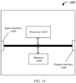
- the communication apparatus includes a communication interface and a processor, and optionally, further includes a memory.
- the memory is configured to store a computer program or instructions.
- the processor is coupled to the memory and the communication interface. When the processor executes the computer program or the instructions, the communication apparatus is enabled to perform the method performed by the terminal device in the foregoing method embodiment.
- a communication apparatus may be the network device in the foregoing method embodiments, or may be a chip disposed in the network device.
- the communication apparatus includes a communication interface and a processor, and optionally, further includes a memory.
- the memory is configured to store a computer program or instructions.
- the processor is coupled to the memory and the communication interface. When the processor executes the computer program or the instructions, the communication apparatus is enabled to perform the method performed by the network device in the foregoing method embodiment.
- a computer program product includes computer program code.
- the computer program product includes computer program code.
- a computer program product includes computer program code.
- the computer program product includes computer program code.
- this application provides a chip system.
- the chip system includes a processor, configured to implement functions of the terminal device in the methods in the foregoing aspects.
- the chip system further includes a memory, configured to store program instructions and/or data.
- the chip system may include a chip, or may include a chip and another discrete component.
- this application provides a chip system.
- the chip system includes a processor, configured to implement functions of the network device in the methods in the foregoing aspects.
- the chip system further includes a memory, configured to store program instructions and/or data.
- the chip system may include a chip, or may include a chip and another discrete component.
- this application provides a computer-readable storage medium.
- the computer-readable storage medium stores a computer program.
- the computer program is run, the methods performed by the terminal device in the foregoing aspects are implemented.
- this application provides a computer-readable storage medium.
- the computer-readable storage medium stores a computer program.
- the computer program is run, the methods performed by the network device in the foregoing aspects are implemented.
- LTE long term evolution
- FDD frequency division duplex
- TDD time division duplex
- 5th generation 5th generation, 5G
- new radio new radio, NR
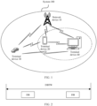
- FIG. 1 is a schematic diagram of a wireless communication system 100 applicable to an embodiment of this application.
- the wireless communication system 100 may include one or more network devices, for example, a network device 10 shown in FIG. 1 .
- the wireless communication system 100 may further include one or more terminal devices, for example, a terminal device 20, a terminal device 30, and a terminal device 40 shown in FIG. 1 .
- FIG. 1 is merely a schematic diagram.
- the communication system may further include another network device, for example, may further include a core network device, a wireless relay device, and a wireless backhaul device, which are not shown in FIG. 1 .
- Numbers of network devices and terminal devices included in the mobile communication system are not limited in embodiments of this application.
- the terminal device 20, the terminal device 30, and the terminal device 40 in this embodiment of this application each may also be referred to as a terminal, a terminal device, a mobile station (mobile station, MS), a mobile terminal (mobile terminal, MT), or the like.
- the terminal device in embodiments of this application may be a mobile phone (mobile phone), a tablet computer (Pad), or a computer with a wireless transceiver function, or may be a wireless terminal applied to a scenario, for example, virtual reality (virtual reality, VR), augmented reality (augmented reality, AR), industrial control (industrial control), self driving (self driving), remote medical (remote medical), a smart grid (smart grid), transportation safety (transportation safety), a smart city (smart city), or a smart home (smart home).
- the terminal device and a chip that can be applied to the terminal device are collectively referred to as a terminal device. It should be understood that a specific technology used by and a specific device form of the terminal device are not limited in embodiments of this application.
- the network device 10 in embodiments of this application may be a device configured to communicate with the terminal device.
- the network device may be a base station, an evolved NodeB (evolved Node B, eNB), a home base station, an access point (access point, AP) in a wireless fidelity (wireless fidelity, Wi-Fi) system, a wireless relay node, a wireless backhaul node, a transmission point (transmission point, TP), a transmission and reception point (transmission and reception point, TRP), or the like, or may be a gNB in an NR system, or may be a component or a part of a device that constitutes a base station, for example, a central unit (central unit, CU), a distributed unit (distributed unit, DU), or a baseband unit (baseband unit, BBU).
- a central unit central unit
- DU distributed unit
- BBU baseband unit
- the network device may be a network device, or may be a chip used in the network device to complete a wireless communication processing function.
- the terminal device or the network device includes a hardware layer, an operating system layer running at the hardware layer, and an application layer running at the operating system layer.
- the hardware layer includes hardware such as a central processing unit (central processing unit, CPU), a memory management unit (memory management unit, MMU), and a memory (which may also be referred to as a main memory).
- An operating system may be any one or more types of computer operating systems that implement service processing through a process (process), for example, a Linux operating system, a Unix operating system, an Android operating system, an iOS operating system, or a Windows operating system.
- the application layer includes applications such as a browser, an address book, word processing software, and instant messaging software.
- an execution body of a method provided in embodiments of this application is not particularly limited in embodiments of this application, provided that a program that records code of the method provided in embodiments of this application can be run to perform communication according to the method provided in embodiments of this application.
- the execution body of the method provided in embodiments of this application may be the terminal device or the network device, or a functional module that can invoke and execute the program in the terminal device or the network device.
- the terminal device 20 to the terminal device 40 each may communicate with the network device 10.
- Link environments of the terminal device 20 to the terminal device 40 each include uplink transmission, downlink transmission, and side-link (side-link) transmission.
- Information transmitted in link transmission may include actually transmitted data information and control information that indicates or is used to schedule actual data.
- the terminal device 20 and the terminal device 40 may also constitute a communication system.
- a link transmission environment of the communication system is consistent with the foregoing descriptions, and specific information may be exchanged based on a network configuration manner.
- aspects or features of this application may be implemented as a method, an apparatus, or a product that uses standard programming and/or engineering technologies.
- product used in this application covers a computer program that can be accessed from any computer-readable component, carrier or medium.
- the computer-readable storage medium may include but is not limited to a magnetic storage component (for example, a hard disk, a floppy disk, or a magnetic tape), an optical disc (for example, a compact disc (compact disc, CD) or a digital versatile disc (digital versatile disc, DVD)), a smart card, and a flash memory component (for example, an erasable programmable read-only memory (erasable programmable read-only memory, EPROM), a card, a stick, or a key drive).
- a magnetic storage component for example, a hard disk, a floppy disk, or a magnetic tape
- an optical disc for example, a compact disc (compact disc, CD) or a digital versatile disc (digital versatile disc, DVD)
- a smart card for example, an erasable programmable read-only memory (erasable programmable read-only memory, EPROM), a card, a stick, or a key drive).
- EPROM erasable programmable read-only memory
- various storage media described in this specification may represent one or more devices and/or other machine-readable storage media that are configured to store information.
- machine-readable storage media may include but is not limited to a radio channel, and various other media that can store, include, and/or carry instructions and/or data.
- first, second, and third in embodiments of this application are merely used for distinguishing, and should not be construed as any limitation on this application.
- first information and second information in embodiments of this application indicate information transmitted between the network device and the terminal device.
- sequence numbers of the processes do not mean execution sequences in various embodiments of this application.
- the execution sequences of the processes should be determined based on functions and internal logic of the processes, and should not be construed as any limitation on the implementation processes of embodiments of this application.
- presetting may be implemented by pre-storing corresponding code or a table in a device (for example, including the terminal device and the network device), or in another manner that may indicate related information.
- a specific implementation of "presetting”, “predefining”, or the like is not limited in this application, for example, a preset rule or a preset constant in embodiments of this application.
- a band is mainly divided into two parts: a frequency range 1 (frequency range 1, FR 1) and an FR 2.
- the FR 1 is mainly a bandwidth of 450 MHz to 6 GHz
- the FR 2 is mainly a bandwidth of 24.25 GHz to 52.6 GHz.
- a band of 52.6 GHz to 71 GHz (above 52.6 GHz for short) is also included in a use range of a post fifth generation mobile communication system (a beyond 5.5G system).
- This band includes a licensed band and an unlicensed band (the unlicensed band may also be referred to as a shared band).
- a band ranging from 59 GHz to 64 GHz is the unlicensed band, and the remaining is the licensed band.
- a band ranging from 57 GHz to 71 GHz is the unlicensed band.
- radio unlicensed new radio unlicensed
- technologies deployed on the shared band are collectively referred to as a radio unlicensed (new radio unlicensed, NRU) band technology.
- NRU new radio unlicensed
- other systems such as radio detection and ranging (radio detection and ranging, radar), wireless fidelity (wireless fidelity, Wi-Fi), and Bluetooth, and another inter-operator access system may be further included on the shared band. Therefore, a system operating on the shared band needs to support all or some of the following key technologies: LBT, transmit power control (transmit power control, TPC), and dynamic frequency selection (dynamic frequency selection, DFS).
- An LBT mechanism means that, before using a channel, various access devices need to first obtain an interference status of a band on which a target channel is located, and the channel can be used only when an interference level of the channel on the target band is less than or equal to a preset threshold.
- a TPC mechanism means that, to avoid affecting a normal communication state of another access device, a sending device operating on the shared band cannot increase transmit power of the sending device without limitation.
- a DFS mechanism means that a system operating on the shared band needs to avoid, in a timely manner, a band on which a high-priority system is located, and dynamically switch to a band with lower interference to work.
- a receiving device that accesses different types of bands first detects an SSB sent by a base station.
- the SSB mainly includes a primary synchronization signal (primary synchronization signal, PSS), a secondary synchronization signal (secondary synchronization signal, SSS), and a PBCH, and includes four orthogonal frequency division multiplexing (orthogonal frequency division multiplexing, OFDM) symbols in time domain and a two-dimensional area of 20 resource blocks (resource blocks, RBs) in frequency domain.
- PSS primary synchronization signal
- SSS secondary synchronization signal
- PBCH primary synchronization signal
- OFDM orthogonal frequency division multiplexing
- the UE may complete cell synchronization and rough symbol-level timing synchronization by demodulating the PSS and the SSS, and can complete timing synchronization at a system frame level by demodulating master information block (master information block, MIB) information carried in the PBCH, and obtain related configuration information of a system information block 1/remaining minimum system information (system information block/remaining minimum system information, SIB 1/RMSI), that is, demodulate a type 0-physical downlink control channel (type 0-physical downlink control channel, type 0-PDCCH) and a physical downlink shared channel (physical downlink shared channel, PDSCH) of the SIB 1/RMSI by using a parameter (pdcch-ConfigSIB 1).
- a control resource set (control resource set, CORESET) #0 is located on the type 0-PDCCH.
- the MIB information carried in the PBCH includes the following parameters:
- a system frame number (“systemFrameNumber”) indicates six least significant bits of a system frame.
- Subcarrier spacing common (“subCarrierSpacingCommon”) indicates subcarriers of the SIB 1, a message 2/4 (Msg.2/4), and on-demand information (on-demand information, OSI).
- An SSB-subcarrier offset (ssb-SubcarrierOffset”) indicates an offset between the SSB and a subcarrier #0 in a common resource block (common resource block, CRB).
- a demodulation reference signal-type A-position (“dmrs-TypeA-Position”) indicates a position of a 1 st DMRS.
- a PDCCH-configuration SIB 1 (“pdcch-ConfigSIB 1 ”) indicates parameter configurations of a CORESET, search space, and a related PDCCH.
- Cell barring (“cellBarred”) indicates whether the terminal device is allowed to access a cell.
- Intra-frequency reselection (“intraFreqReselection”) indicates cell selection or reselection of the terminal device on a band.
- Spare is a remaining bit that is temporarily not used.
- a same parameter in the MIB information represents different content on the licensed band and the shared band.
- the base station in consideration of existence of the LBT mechanism, the base station cannot send a specified SSB at a specified position. Therefore, a new Q value (namely, N SSB QCL ) is defined, may be represented by using two bits, and may have a value being ⁇ 1, 2, 4, 8 ⁇ .
- the UE may calculate, by demodulating the Q value and based on a DMRS sequence, a plurality of candidate positions for sending a same SSB index. These candidate positions are understood as having a same quasi co-location (quasi co-location, QCL) relationship for the UE, for example, corresponding to a same downlink beam direction.
- QCL quasi co-location
- an R16 NRU system newly defines a DBTW and a DB.
- the DB includes a group of downlink (down link, DL) transmission signals, for example, an SS/PBCH block and the RMSI information.
- the base station can pack the SS/PBCH block and the RMSI in a DB manner by using a single LBT mechanism and send the packed SS/PBCH block and RMSI at the same time.
- FIG. 2 A relationship between the DBTW and the DB in time domain is shown in FIG. 2 .
- the DB sent by the base station may appear at different positions within the DBTW.
- the terminal device does not know a status of the DBTW, and therefore cannot implement fast timing synchronization with the network device.
- this application provides a communication method, so that a terminal device can determine a status of a DBTW, to quickly implement timing synchronization with a network device.
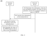
- FIG. 3 is a schematic flowchart of a communication method according to an embodiment of this application.
- the method may be performed by a terminal device and a network device, or may be performed by a chip in a terminal device and a chip in a network device.
- the communication method 300 may be applied to an unlicensed band.
- the communication method 300 may include the following steps.
- the network device determines first information, where the first information includes a Q value or a first parameter, and the first parameter indicates a status of a DBTW.
- the network device sends the first information to the terminal device.
- the steps 310 and 320 may be performed by the network device 10 in FIG. 1 .
- the terminal device receives the first information sent by the network device.
- the terminal device determines the status of the DBTW based on the Q value or the first parameter.
- the steps 330 and 340 may be performed by any one or more of the terminal device 20 to the terminal device 40 in FIG. 1 .
- the first information in this application may be the foregoing SSB.
- the SSB includes a PBCH, and the PBCH carries MIB information including the Q value.
- a terminal device that accesses different types of bands may detect the SSB sent by the network device.
- the SSB includes the PBCH.
- the terminal device may complete timing synchronization by demodulating the MIB information carried in the PBCH.
- the terminal device can determine the status of the DBTW based on the Q value in the MIB information, to quickly implement timing synchronization with the network device.
- the terminal device can determine the status of the DBTW based on the first information sent by the network device, therefore can determine whether the network device sends, within the DBTW, an SSB that cannot be sent due to an LBT failure, and further, can quickly implement timing synchronization with the network device.
- the terminal device can determine the status of the DBTW based on the Q value or the first parameter.
- the following first describes a case in which the terminal device determines the status of the DBTW based on the Q value.
- the determining the status of the DBTW based on the Q value includes:
- the terminal device may determine the status of the DBTW based on a value relationship between the Q value and the first threshold. For details, refer to Case 1 and Case 2 in the following.
- Case 1 Q is greater than or equal to the first threshold, and the terminal device determines that the DBTW is in the disabled state.
- the terminal device may consider that the DBTW is in the disabled state.
- the terminal device can consider that the DBTW is in the disabled state, that is, the network device does not send, within the DBTW, the SSB that is actually not sent due to the LBT failure.
- a frequency for example, 120 kHz, 480 kHz, or 960 kHz
- Case 2 Q is less than 64, and the terminal device determines to determine the status of the DBTW based on the DBTW value.
- the terminal device may further determine the status of the DBTW based on the DBTW value.
- the first threshold and/or the second threshold in this embodiment of this application may be specified in a protocol, or may be configured by the network device. This is not limited. It should be understood that the first threshold may be a number of candidate SSBs within the DBTW.
- UE if Q is greater than or equal to the number of candidate SSBs within the DBTW, UE considers that the DBTW is disabled. If Q is less than the number of candidate SSBs within the DBTW, UE may consider that the DBTW is enabled.
- a related expression in English may be as follows.
- the network device may define the second threshold by using a parameter “discovery burst window length” (discoveryburst-windowlength) or a parameter “discovery burst window length-r17” (discoveryburst-windowlength-r17) in RRC signaling.
- Table 1 Bit/index Q value DBTW value (ms) at 120 kHz/480 kHz/960 kHz Note 000/0 8 0.5/0.125/0.075
- a DBTW configured by a base station is not greater than a value listed in the table, the UE considers by default that the DBTW is disabled. Otherwise, the UE considers by default that the DBTW is enabled.
- the UE considers by default that the DBTW is enabled.
- the Q value and the DBTW value are carried in serving cell configuration common in RRC signaling or a serving cell configuration common SIB in SIB 1 information.
- DiscoveryBurstWindowLength-r17 ⁇ ms0dot5 , ms1, ms2, ms2dot25, ms2dot5, ms3, ms3dot5, ms4, ms5 ⁇ .
- the Q value may be indicated by using three bits, but a same index may correspond to different Q values, and thresholds of corresponding DBTW values may also be different.
- a Q value corresponding to an index "0" is 8, and a threshold of a corresponding DBTW value when the SCS of the SSB is 120 kHz, 480 kHz, or 960 kHz is 0.5 ms, 0.125 ms, or 0.075 ms.
- the terminal device may receive the Q value at a frequency of 120 kHz. If the DBTW value configured by the network device is 0.4 ms, because 0.4 ms is less than the corresponding threshold 0.5 ms at 120 kHz, the terminal device may consider that the DBTW is in the disabled state. If the DBTW value configured by the network device is 0.6 ms, because 0.6 ms is greater than the corresponding threshold 0.5 ms at 120 kHz, the terminal device may consider that the DBTW is in the enabled state.
- the terminal device may alternatively receive the Q value at a frequency of 480 kHz. If the DBTW value configured by the network device is 0.1 ms, because 0.1 ms is less than the corresponding threshold 0.125 ms at 480 kHz, the terminal device may consider that the DBTW is in the disabled state. If the DBTW value configured by the network device is 0.2 ms, because 0.2 ms is greater than the corresponding threshold 0.125 ms at 480 kHz, the terminal device may consider that the DBTW is in the enabled state.
- the terminal device may alternatively receive the Q value at a frequency of 960 kHz. If the DBTW value configured by the network device is 0.05 ms, because 0.05 ms is less than the corresponding threshold 0.075 ms at 960 kHz, the terminal device may consider that the DBTW is in the disabled state. If the DBTW value configured by the network device is 0.1 ms, because 0.1 ms is greater than the corresponding threshold 0.075 ms at 960 kHz, the terminal device may consider that the DBTW is in the enabled state.
- a Q value corresponding to an index "0" is 1, and a threshold of a corresponding DBTW value when the SCS of the SSB is 120 kHz, 480 kHz, or 960 kHz is 0.075 ms, 0.01875 ms, or 0.09375 ms.
- the terminal device may receive the Q value at a frequency of 120 kHz. If the DBTW value configured by the network device is 0.05 ms, because 0.05 ms is less than the corresponding threshold 0.075 ms at 120 kHz, the terminal device may consider that the DBTW is in the disabled state. If the DBTW value configured by the network device is 0.1 ms, because 0.1 ms is greater than the corresponding threshold 0.075 ms at 120 kHz, the terminal device may consider that the DBTW is in the enabled state.
- the terminal device may alternatively receive the Q value at a frequency of 480 kHz. If the DBTW value configured by the network device is 0.01 ms, because 0.01 ms is less than the corresponding threshold 0.01875 ms at 480 kHz, the terminal device may consider that the DBTW is in the disabled state. If the DBTW value configured by the network device is 0.02 ms, because 0.02 ms is greater than the corresponding threshold 0.01875 ms at 480 kHz, the terminal device may consider that the DBTW is in the enabled state.
- the terminal device may alternatively receive the Q value at a frequency of 960 kHz. If the DBTW value configured by the network device is 0.05 ms, because 0.05 ms is less than the corresponding threshold 0.09375 ms at 960 kHz, the terminal device may consider that the DBTW is in the disabled state. If the DBTW value configured by the network device is 0.1 ms, because 0.1 ms is greater than the corresponding threshold 0.09375 ms at 960 kHz, the terminal device may consider that the DBTW is in the enabled state.
- a slot occupied by the DBTW, the configured Q value, and the DBTW value may alternatively be determined based on a ratio factor. It is assumed that the Q value, a number of slots occupied by the DBTW, a number of symbols occupied by the DBTW, and the DBTW value are respectively A, B, C, and D, and values of A, B, C, and D are based on a first SCS (for example, 120 kHz).
- a first SCS for example, 120 kHz
- a Q value, a number of slots occupied by the DBTW, a number of symbols occupied by the DBTW, and a DBTW value that are at the second SCS are respectively represented as follows: A ⁇ X, B ⁇ X, C ⁇ X ⁇ 14, and D/X.
- the terminal device implicitly obtains the ratio factor based on the second SCS supported in a band range supported by a serving cell that the terminal device accesses, or implicitly obtains, through calculation based on the ratio factor, the Q value, the number of slots occupied by the DBTW, the number of symbols occupied by the DBTW, and the DBTW value that are at the second SCS.
- the ratio factor may be defined in the parameter "serving cell configuration common” included in the RRC signaling, or may be carried in the parameter "serving cell configuration common SIB", or may be configured in the MIB. This is not limited.
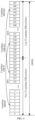
- FIG. 4 is a schematic diagram of a manner of sending an SSB (when a DBTW is in an enabled state) according to an embodiment of this application.
- Q 32
- DBTW 5 ms. Therefore, within the DBTW, last 32 candidate SSB positions may be used to send an actual SSB that cannot be sent due to an LBT failure.
- the SSBs at different candidate SSB positions have a first QCL relationship
- the first QCL relationship may indicate that the SSBs at the different candidate SSB positions have a same index.
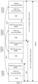
- FIG. 5 A manner of cyclically placing the SSB and corresponding RMSI that have a second QCL relationship is shown in FIG. 5 .
- a PDCCH indicating the RMSI represents a type 0-PDCCH carrying a CORESET #0, and includes related configuration information indicating the RMSI (or a SIB 1).
- a PDSCH channel transmitting the RMSI represents a PDSCH channel transmitting the RMSI (or the SIB 1).
- the terminal device receives, by using a same receive beam, the SSB and the type 0-PDCCH and the RMSI PDSCH that meet the second QCL relationship.
- FIG. 5 shows only one coexistence manner of the SSB, the type 0-PDCCH, and the RMSI for PDSCH.
- the type 0-PDCCH, the SSB, and the RMSI for PDSCH may exist in any TDM or FDM manner.
- a time domain position of the type 0-PDCCH may be before or after the SSB, but is generally located on or in one or more symbols or slots before the RMSI for PDSCH.
- the terminal device determines the status of the DBTW based on the value relationship between the Q value and the first threshold. If the status of the DBTW cannot be determined, the terminal device can further determine the status of the DBTW based on the DBTW value. In this way, it can be determined whether the network device sends, within the DBTW, the SSB that cannot be sent due to the LBT failure, to quickly implement timing synchronization with the network device.
- the terminal device may consider that the DBTW is in the disabled state, or if the DBTW value is greater than the second threshold, the terminal device may consider that the DBTW is in the enabled state.
- the second threshold may be determined in the following manner.
- the second threshold is time duration from a 1 st symbol in a slot in which a first SSB is located to a last symbol in a slot in which a second SSB is located.
- An index of the first SSB is 0, and an index of the second SSB is (Q-1).
- the second threshold is time duration from a 1 st symbol in a slot in which a third SSB is located to a last symbol in a slot in which a fourth SSB is located.
- the third SSB is located in a first SSB group
- the fourth SSB is located in a second SSB group.
- the first SSB group is a 1 st group whose bit is configured as "1" from the left in a second parameter.
- the second SSB group is a 1 st group whose bit is configured as "1" from the right in the second parameter.
- the second threshold is time duration from a 1 st symbol in a slot in which a fifth SSB is located to a last symbol in a slot in which a sixth SSB is located.
- the fifth SSB is an SSB with a smallest index in successfully sent SSBs
- the sixth SSB is an SSB with a largest index in the successfully sent SSBs.
- the second threshold is time duration from a slot in which a first SSB is located to a slot in which a second SSB is located.
- An index of the first SSB is 0, and an index of the second SSB is (Q-1).
- the second threshold is time duration from a slot in which a third SSB is located to a slot in which a fourth SSB is located.
- the third SSB is located in a first SSB group
- the fourth SSB is located in a second SSB group.
- the first SSB group is a 1 st group whose bit is configured as "1" from the left in a second parameter.
- the second SSB group is a 1 st group whose bit is configured as "1" from the right in the second parameter.
- the second threshold is time duration from a slot in which a fifth SSB is located to a slot in which a sixth SSB is located.
- the fifth SSB is an SSB with a smallest index in successfully sent SSBs
- the sixth SSB is an SSB with a largest index in the successfully sent SSBs.
- the second threshold is time duration from a 1 st symbol of a first SSB to a last symbol of a second SSB.
- An index of the first SSB is 0, and the second SSB is (Q-1).
- the second threshold is time duration from a 1 st symbol of a third SSB to a last symbol of a fourth SSB.
- the third SSB is located in a first SSB group
- the fourth SSB is located in a second SSB group.
- the first SSB group is a 1 st group whose bit is configured as "1" from the left in a second parameter.
- the second SSB group is a 1 st group whose bit is configured as "1" from the right in the second parameter.
- the second threshold is time duration from a 1 st symbol of a fifth SSB to a last symbol of a sixth SSB.
- the fifth SSB is an SSB with a smallest index in successfully sent SSBs
- the sixth SSB is an SSB with a largest index in the successfully sent SSBs.
- the fifth SSB and/or the sixth SSB in this embodiment of this application may be jointly indicated by using the parameter "groupPresence” and a parameter "inonegroup” in the serving cell configuration common SIB.
- DBTW is larger than (or equal to or larger than, or not smaller than) the time duration from the beginning of slot containing the candidate SSB index 0 to the end of slot containing the candidate SSB index Q-1, UE assumes that DBTW is enabled.
- the UE considers by default that the DBTW is disabled.
- the UE considers by default that the DBTW is enabled.
- DBTW equals to (or equal to or smaller than, or not larger than) the time duration from the beginning of the half frame that contains the SS/PBCH blocks to the end of the slot that contains the SS/PBCH blocks within the SS/PBCH blocks group corresponding to the last/rightmost bit with value 1 in groupPresence in ServingCellConfigCommonSIB, UE assumes that DBTW is disabled.
- DBTW is larger than (or equal to or larger than, or not smaller than) the time duration from the beginning of the half frame that contains the SS/PBCH blocks to the end of the slot that contains the SS/PBCH blocks within the SS/PBCH blocks group corresponding to the last/rightmost bit with value 1 in groupPresence in ServingCellConfigCommonSIB, UE assumes that DBTW is enabled.
- (a length or a value of) the DBTW is equal to, or less than or equal to, or not greater than time duration from a start slot in which first SS/PBCH blocks included (in the half-frame) are located to an end slot in which second SS/PBCH blocks included (in the half-frame) are located.
- the first SS/PBCH blocks and the second SS/PBCH blocks are located in the SS/PBCH blocks group.
- the SS/PBCH blocks group is located in a group with a last or rightmost bit indicated as "1" in the parameter "groupPresence" in the parameter "ServingCellConfigCommonSIB". In this case, the UE considers by default that the DBTW is disabled.
- a length or a value of) the DBTW is greater than, or greater than or equal to, or not less than time duration from a start slot in which first SS/PBCH blocks included (in the half-frame) are located to an end slot in which second SS/PBCH blocks included (in the half-frame) are located.
- the first SS/PBCH blocks and the second SS/PBCH blocks are located in the SS/PBCH blocks group.
- the SS/PBCH blocks group is located in a group with a last or rightmost bit indicated as "1" in the parameter "groupPresence" in the parameter "ServingCellConfigCommonSIB". In this case, the UE considers by default that the DBTW is enabled.
- DBTW equals to (or equal to or smaller than, or not larger than) the time duration from the beginning of the half frame that contains the SS/PBCH blocks to the end of the slot that contains the last transmitted SS/PBCH block (SS/PBCH block with the largest index) that is indicated jointly by inOneGroup and groupPresence in ServingCellConfigCommonSIB, UE assumes that DBTW is disabled.
- DBTW is larger than (or equal to or larger than, or not smaller than) the time duration from the beginning of the half frame that contains the SS/PBCH blocks to the end of the slot that contains the last transmitted SS/PBCH block (SS/PBCH block with the largest index) that is indicated jointly by inOneGroup and groupPresence in ServingCellConfigCommonSIB, UE assumes that DBTW is enabled.
- the DBTW is equal to, or less than or equal to, or not greater than time duration from a start slot in which first SS/PBCH blocks included (in the half-frame) are located to a last slot in which second SS/PBCH blocks included (in the half-frame) are located.
- the second SS/PBCH blocks have a largest index.
- the first SS/PBCH blocks and the second SS/PBCH blocks are jointly indicated by using the parameter "groupPresence" and the parameter "inOneGroup” in the parameter "ServingCellConfigCommonSIB". In this case, the UE considers by default that the DBTW is disabled.
- a length or a value of) the DBTW is greater than, or greater than or equal to, or not less than time duration from a start slot in which first SS/PBCH blocks included (in the half-frame) are located to a last slot in which second SS/PBCH blocks included (in the half-frame) are located.
- the second SS/PBCH blocks have a largest index.
- the first SS/PBCH blocks and the second SS/PBCH blocks are jointly indicated by using the parameter "groupPresence" and the parameter "inOneGroup” in the parameter "ServingCellConfigCommonSIB". In this case, the UE considers by default that the DBTW is enabled.
- the terminal device may alternatively determine the status of the DBTW in the following manner.
- DBTW equals to (or equal to or smaller than, or not larger than) the time duration from the beginning of the half frame that contains the SS/PBCH blocks to the end of the slot that contains at least the last SS/PBCH blocks within the SS/PBCH blocks group corresponding to the last/rightmost bit with value 1 in groupPresence in ServingCellConfigCommonSIB, UE assumes that DBTW is disabled.
- DBTW is larger than (or equal to or larger than, or not smaller than) the time duration from the beginning of the half frame that contains the SS/PBCH blocks to the end of the slot that contains at least the last SS/PBCH blocks within the SS/PBCH blocks group corresponding to the last/rightmost bit with value 1 in groupPresence in ServingCellConfigCommonSIB, UE assumes that DBTW is enabled.
- (a length or a value of) the DBTW is equal to, or less than or equal to, or not greater than time duration from a start slot in which first SS/PBCH blocks included (in the half-frame) are located to an end slot in which at least second SS/PBCH blocks included (in the half-frame) are located.
- the first SS/PBCH blocks and the second SS/PBCH blocks are located in the SS/PBCH blocks group.
- the SS/PBCH blocks group is located in a group with a last or rightmost bit indicated as "1" in the parameter "groupPresence" in the parameter "ServingCellConfigCommonSIB". In this case, the UE considers by default that the DBTW is disabled.
- a length or a value of) the DBTW is greater than, or greater than or equal to, or not less than time duration from a start slot in which first SS/PBCH blocks included (in the half-frame) are located to an end slot in which at least second SS/PBCH blocks included (in the half-frame) are located.
- the first SS/PBCH blocks and the second SS/PBCH blocks are located in the SS/PBCH blocks group.
- the SS/PBCH blocks group is located in a group with a last or rightmost bit indicated as "1" in the parameter "groupPresence" in the parameter "ServingCellConfigCommonSIB". In this case, the UE considers by default that the DBTW is enabled.
- the network device may send the first information to the terminal device, and the first information may include the Q value.
- the Q value For a bit indication manner of the Q value, refer to the following.
- the Q value is indicated by using n bits, and n is a positive integer greater than 2.
- the n bits include at least one bit indicating a third parameter.
- the third parameter includes at least one of the following parameters: subcarrier spacing common in the MIB information, an SSB-subcarrier offset in the MIB information, and a PDCCH-configuration SIB 1 in the MIB information.
- the PDCCH-configuration SIB 1 includes search space zero and a control resource set zero.
- the Q value in this embodiment of this application can be a positive integer greater than 2, and the n bits can be the at least one bit indicating the foregoing parameter.
- the Q value may be indicated by using three or four bits, and the three bits or the four bits may be the at least one bit in the foregoing parameter.
- the n bits may include n bits indicating the subcarrier spacing common, or may include n bits indicating the subcarrier spacing common and the SSB-subcarrier offset, or may include n bits indicating the carrier spacing common, the SSB-subcarrier offset, and the PDCCH-configuration SIB 1. This is not limited.
- the Q value can be indicated by using the n bits, and the n bits include the at least one bit indicating the third parameter.
- the bits indicating the Q value can be a corresponding bit of another parameter in the MIB. This can improve system performance.
- the n bits include n1 bits indicating a fourth parameter and (n-n1) bits indicating a fifth parameter.
- the fourth parameter is any parameter in the third parameter
- the fifth parameter is a parameter in the third parameter other than the fourth parameter.
- the fifth parameter is indicated by using m-(n-n1) bits, and m is an initial number indicating the fifth parameter.
- the n bits include n1 bits indicating a fourth parameter and (n-n1) bits indicating a fifth parameter.
- the fourth parameter is any parameter in the third parameter
- the fifth parameter is a parameter in the third parameter other than the fourth parameter.
- the fifth parameter is indicated by using m bits, m is an initial number indicating the fifth parameter, and (n-n1) ⁇ m.
- the n bits indicating the Q value include the n1 bits indicating the fourth parameter and the (n-n1) bits indicating the fifth parameter, and the initial number indicating the fifth parameter is m. Therefore, (n-n1) ⁇ m.
- the fourth parameter may be the subcarrier spacing common in the MIB information
- the fifth parameter may be the SSB-subcarrier offset in the MIB information and/or the PDCCH-configuration SIB 1 in the MIB information.
- the fourth parameter may be the SSB-subcarrier offset in the MIB information
- the fifth parameter may be the subcarrier spacing common in the MIB information and/or the PDCCH-configuration SIB 1 in the MIB information.
- the fourth parameter may be the PDCCH-configuration SIB 1 in the MIB information
- the fifth parameter may be the subcarrier spacing common in the MIB information and/or the SSB-subcarrier offset in the MIB information. This is not limited.
- n may be three or four bits, that is, the Q value may be indicated by using the three or four bits.
- the Q value may be indicated by using the three or four bits.
- the parameter "PDCCH-configuration SIB 1" is indicated by using eight bits.
- the parameter "PDCCH-configuration SIB 1" includes the parameter "search space zero" ("searchSpaceZero", which occupies four bits) and the parameter "control resource set zero" ("controlResourceSetZero", which occupies four bits). Therefore, the three bits indicating the Q value may include the two bits indicating the parameter "subcarrier spacing common” and one bit indicating the parameter "search space zero", or may include the two bits indicating the parameter "subcarrier spacing common" and one bit indicating the parameter "control resource set zero".
- the parameter "SSB-subcarrier offset" may be initially indicated by using four bits, and the Q value may be indicated by using two of the four bits.
- the parameter "PDCCH-configuration SIB 1" is indicated by using eight bits.
- the parameter "PDCCH-configuration SIB 1" includes the parameter "search space zero" (which occupies four bits) and the parameter "control resource set zero" (which occupies four bits). Therefore, the three bits indicating the Q value may include the two bits indicating the parameter "SSB-subcarrier offset” and one bit indicating the parameter "search space zero", or may include the two bits indicating the parameter "SSB-subcarrier offset” and one bit indicating the parameter "control resource set zero".
- the parameter "SSB-subcarrier offset" may be initially indicated by using four bits, and the Q value may be indicated by using one of the four bits.
- the parameter "PDCCH-configuration SIB 1" is indicated by using eight bits.
- the parameter "PDCCH-configuration SIB 1" includes the parameter "search space zero" (which occupies four bits) and the parameter "control resource set zero” (which occupies four bits). Therefore, the three bits indicating the Q value may include the bit indicating the parameter "SSB-subcarrier offset” and two bits indicating the parameter “search space zero”, or may include the bit indicating the parameter "SSB-subcarrier offset” and two bits indicating the parameter “control resource set zero”, or may include the bit indicating the parameter "SSB-subcarrier offset", one bit indicating the parameter "search space zero", and one bit indicating the parameter "control resource set zero". This is not limited.
- n bits include the two bits indicating the parameter "PDCCH-configuration SIB 1"
- the two bits are respectively the bit indicating "search space zero” and the bit indicating the parameter "control resource set zero”
- both the two bits may be misappropriated to indicate the Q value, or may be borrowed to indicate the Q value.
- the bit indicating "search space zero” is misappropriated to indicate the Q value
- the bit indicating the parameter "control resource set zero” is borrowed to indicate the Q value.
- the bit indicating "search space zero” is borrowed to indicate the Q value
- the bit indicating the parameter "control resource set zero” is misappropriated to indicate the Q value. This is not limited.
- Table 5 Bit/index Q value 000/0 8 001/1 16 010/2 32 011/3 64 100/4 >64 (for example, 128 or 256) 101/5 Reserved (reserved) 110/6 Reserved (reserved) 111/7 Reserved (reserved) Table 6 Bit/index Q value 000/0 1 001/1 2 010/2 4 011/3 8 100/4 16 101/5 32 110/6 64 111/7 >64 (for example, 128 or 256) Table 7 Bit/index Q value 000/0 8 001/1 16 010/2 24 011/3 32 100/4 48 101/5 52 110/6 64 111/7 Reserved (reserved) Table 8 Bit/index Q value 000/0 8 001/1 16 010/2 24 011/3 32 100/4 48 101/5 52 110/6 64 111/7 Reserved (reserved) Table 8 Bit/index Q value 000/0 8 001/1 16 010/2 24 011/3 32 100/4 48 101/5 52 110/6 60 111/7 64 Table 9 Bit/index DBTW value (ms) DBTW length
- the Q value may be indicated by using three bits, but a same index may correspond to different Q values.
- a Q value corresponding to an index "0" is 8.
- a Q value corresponding to the index "0" is 1.
- Q value may not be limited to a number shown in the table, and the Q value may be extended to any number from 1 to 128. This is not limited.
- the two bits that indicate the parameter "SSB-subcarrier offset" and that are included in the four bits may be misappropriated or borrowed.
- the four bits include two bits indicating the parameter "subcarrier spacing common" and two bits indicating the parameter "PDCCH-configuration SIB 1".
- the two bits that indicate the parameter "PDCCH-configuration SIB 1" and that are included in the four bits may be two bits indicating the parameter "search space zero” included in the parameter "PDCCH-configuration SIB 1", or may be two bits indicating the parameter "control resource set zero” included in the parameter "PDCCH-configuration SIB 1", or may be one bit indicating the parameter "search space zero” and one bit indicating the parameter "control resource set zero”. This is not limited.
- the four bits include two bits indicating the parameter "subcarrier spacing common”, one bit indicating the parameter "SSB-subcarrier offset”, and one bit indicating the parameter "PDCCH-configuration SIB 1".
- bit that indicates the parameter "SSB-subcarrier offset” and that is included in the four bits or the bit indicating the parameter "PDCCH-configuration SIB 1" may be misappropriated or borrowed.
- the four bits include one bit indicating the parameter "subcarrier spacing common”, one bit indicating the parameter "SSB-subcarrier offset”, and two bits indicating the parameter "PDCCH-configuration SIB 1".
- the bit that indicates the parameter "SSB-subcarrier offset” and that is included in the four bits or the two bits indicating the parameter "PDCCH-configuration SIB 1" may be misappropriated or borrowed.
- the four bits include one bit indicating the parameter "subcarrier spacing common”, two bits indicating the parameter "SSB-subcarrier offset”, and one bit indicating the parameter "PDCCH-configuration SIB 1".
- the two bits that indicate the parameter "SSB-subcarrier offset” and that are included in the four bits or the bit indicating the parameter "PDCCH-configuration SIB 1" may be misappropriated or borrowed.
- the four bits include one bit indicating the parameter "subcarrier spacing common" and three bits indicating the parameter "PDCCH-configuration SIB 1".
- the three bits that indicate the parameter "PDCCH-configuration SIB 1" and that are included in the four bits may be misappropriated or borrowed.
- the four bits include one bit indicating the parameter "subcarrier spacing common" and three bits indicating the parameter "SSB-subcarrier offset”.
- the three bits that indicate the parameter "SSB-subcarrier offset" and that are included in the four bits may be misappropriated or borrowed.
- the four bits include one bit indicating the parameter "SSB-subcarrier offset” and three bits indicating the parameter "PDCCH-configuration SIB 1".
- the bit that indicates the parameter "SSB-subcarrier offset” and that is included in the four bits or the three bits indicating the parameter "PDCCH-configuration SIB 1" may be misappropriated or borrowed.
- the fourth bits include two bits indicating the parameter "SSB-subcarrier offset” and two bits indicating the parameter "PDCCH-configuration SIB 1".
- the two bits that indicate the parameter "SSB-subcarrier offset" and that are included in the four bits or the two bits indicating the parameter "PDCCH-configuration SIB 1" may be misappropriated or borrowed.
- the four bits include three bits indicating the parameter "SSB-subcarrier offset” and one bit indicating the parameter "PDCCH-configuration SIB 1".
- the three bits that indicate the parameter "SSB-subcarrier offset” and that are included in the four bits or the bit indicating the parameter "PDCCH-configuration SIB 1" may be misappropriated or borrowed.
- Table 11 Bit/index Q value 0000/0 1 0001/1 2 0010/2 4 0011/3 8 0100/4 12 0101/5 16 0110/6 24 0111/7 32 1000/8 36 1001/9 40 1010/10 44 1011/11 48 1100/12 52 1101/13 56 1110/14 60 1111/15 64
- Table 12 Bit/index Q value 0000/0 2 0001/1 4 0010/2 8 0011/3 12 0100/4 16 0101/5 20 0110/6 24 0111/7 32 1000/8 36 1001/9 40 1010/10 44 1011/11 48 1100/12 52 1101/13 56 1110/14 60 1111/15 64
- Table 13 Bit/index Q value 0000/0 1 0001/1 2 0010/2 4 0011/3 8 0100/4 16 0101/5 24 0110/6 32 0111/7 36 1000/8 48 1001/9 52 1010/10 56 1011/11 64 1100/12 >64 1101/13 Reserved (reserved) 1110/14 Reserved (reserve
- the Q value may be indicated by using four bits, but a same index may correspond to different Q values.
- a Q value corresponding to an index "0" is 1.
- a Q value corresponding to the index "0" is 2.
- Q value may not be limited to a number shown in the table, and the Q value may be extended to any number from 1 to 128. This is not limited.
- a slot occupied by the DBTW, the configured Q value, and the DBTW value may alternatively be determined based on a ratio factor.
- the Q value, a number of slots occupied by the DBTW, a number of symbols occupied by the DBTW, and the DBTW value are respectively A, B, C, and D, and values of A, B, C, and D are based on a first SCS (for example, 120 kHz).
- a Q value, a number of slots occupied by the DBTW, a number of symbols occupied by the DBTW, and a DBTW value that are at the second SCS are respectively represented as follows: A ⁇ X, B ⁇ X, C ⁇ X ⁇ 14, and D/X.
- the terminal device implicitly obtains the ratio factor based on the second SCS supported in a band range supported by a serving cell that the terminal device accesses, or implicitly obtains, through calculation based on the ratio factor, the Q value, the number of slots occupied by the DBTW, the number of symbols occupied by the DBTW, and the DBTW value that are at the second SCS.
- the ratio factor may be defined in the parameter "serving cell configuration common” included in the RRC signaling, or may be carried in the parameter "serving cell configuration common SIB", or may be configured in the MIB. This is not limited.
- DiscoveryBurstWindowLength-r17 ⁇ ms0dot075, ms0dot125, ms0dot25, ms0dot5, ms1, ms2, ms2dot25, ms2dot5, ms3, ms3dot5, ms4, ms4dot5, ms5 ⁇ at 120 kHz.
- the Q value used to determine the status of the DBTW can be indicated by using the n bits.
- the n bits include the n1 bits indicating the fourth parameter and the (n-n1) bits indicating the fifth parameter.
- the fifth parameter is indicated by using the m-(n-n1) bits, and m is the initial number indicating the fifth parameter.
- the Q value can be indicated by using the corresponding bit of the another parameter in the MIB. This can avoid indicating the Q value by expanding the MIB payload capacity, thereby improving system performance.
- the Q value used to determine the status of the DBTW can be indicated by using the n bits.
- the n bits include the n1 bits indicating the fourth parameter and the (n-n1) bits indicating the fifth parameter.
- the fifth parameter is indicated by using the m bits.
- the Q value can be indicated by using the corresponding bit of the another parameter in the MIB. This can avoid indicating the Q value by expanding the MIB payload capacity, and does not affect bit indication of the fifth parameter, thereby improving system performance.
- the n bits indicating the Q value may include the n1 bits indicating the fourth parameter and the (n-n1) bits indicating the fifth parameter.
- the fifth parameter may be the SSB-subcarrier offset.
- an offset value of the SSB-subcarrier offset may be determined in the following manner.
- the fifth parameter is the SSB-subcarrier offset in the MIB information.
- the offset value of the SSB-subcarrier offset is determined based on a combination of an SCS of the SSB and an SCS of a CRB.
- the offset value of the SSB-subcarrier offset is determined based on a preset threshold.
- the offset value of the SSB-subcarrier offset is a value indicated by the (n-n1) bits of the fifth parameter.
- the offset value of the SSB-subcarrier offset is less than or equal to a value indicated by the (n-n1) bits of the fifth parameter.
- the offset value of the SSB-subcarrier offset may be understood as an offset value between the SSB and the CRB at a subcarrier granularity. It is assumed that the offset value between the SSB and the CRB at the subcarrier granularity is K SSB .
- the offset value is related to the four bits indicating the parameter "SSB-subcarrier offset" (that is, indicating a parameter k ssb _1 ).
- the first frequency, the second frequency, and the third frequency in this embodiment of this application are respectively 120 kHz, 480 kHz, and 960 kHz.
- K SSB k ssb _1 , that is, a value of K SSB is a value indicated by the four bits of the parameter k ssb _1 .
- K SSB 14 .
- the SCS of the SSB is the third frequency
- the SCS of the CRB is the first frequency
- the SCS of the SSB and the SCS of the CRB are ⁇ 960 kHz, 120 kHz ⁇ , that is, a value of K SSB is less than or equal to a value indicated by the four bits of the parameter k ssb _1 .
- the n bits indicating the Q value may include the n1 bits indicating the fourth parameter and the (n-n1) bits indicating the fifth parameter.
- the (n-n1) bits are (n-n1) most significant bits in the fifth parameter.
- the (n-n1) bits are (n-n1) least significant bits in the fifth parameter.
- the (n-n1) bits are any (n-n1) bits in the fifth parameter.
- the Q value is indicated by using three bits, and the three bits include the two bits indicating the parameter "subcarrier spacing common" and the bit indicating the parameter "SSB-subcarrier offset" (namely, (a) in Case 1).
- the bit indicating the parameter "SSB-subcarrier offset” may be one most significant bit in the parameter "SSB-subcarrier offset”.
- the bit indicating the parameter "SSB-subcarrier offset” may be one least significant bit in the parameter "SSB-subcarrier offset”.
- the bit indicating the parameter "SSB-subcarrier offset” may be any one bit in the parameter "SSB-subcarrier offset”. This is not limited.
- the Q value is indicated by using four bits, and the four bits include the two bits indicating the parameter "subcarrier spacing common" and the two bits indicating the parameter "SSB-subcarrier offset" (namely, (a) in Case 2).
- the bit indicating the parameter "SSB-subcarrier offset” may be two most significant bits in the parameter "SSB-subcarrier offset”.
- the bit indicating the parameter "SSB-subcarrier offset” may be two least significant bits in the parameter "SSB-subcarrier offset”.
- the bit indicating the parameter "SSB-subcarrier offset” may be any two bits in the parameter "SSB-subcarrier offset". This is not limited.
- the two most significant bits in the parameter "SSB-subcarrier offset” in this embodiment of this application may be understood as follows: If it is assumed that the parameter "SSB-subcarrier offset" is initially indicated by using four bits (for example, 1011), the two most significant bits in the parameter "SSB-subcarrier offset” are first two bits from the left, namely, "10".
- the two least significant bits in the parameter "SSB-subcarrier offset" in this embodiment of this application may be understood as follows: If it is assumed that the parameter "SSB-subcarrier offset" is initially indicated by using four bits (for example, 1011), the two least significant bits in the parameter "SSB-subcarrier offset” are first two bits from the right, namely, "11".
- the foregoing describes a case in which the terminal device may determine the status of the DBTW based on the Q value, and the following describes a case in which the terminal device determines the status of the DBTW based on the first parameter.
- the determining the status of the DBTW based on the first parameter includes:
- the network device may send the first parameter to the terminal device, and the first parameter may indicate the status of the DBTW.
- the first parameter may be "enabling a discovery burst window length-r17 (enbleDiscoveryBurstWindowLength-r17)", to explicitly indicate the status of the DBTW.
- the first parameter is carried in serving cell configuration common in RRC signaling or a serving cell configuration common SIB in MIB information.
- the first parameter can be carried (or configured) in the parameter "serving cell configuration common" included in the RRC signaling, or can be carried in the parameter "serving cell configuration common SIB".
- the terminal device may determine, after receiving the first parameter, the status of the DBTW based on the first parameter in the parameter "serving cell configuration common", or obtain the first parameter from the parameter "serving cell configuration common SIB" through demodulation to determine the status of the DBTW.
- a possible manner of the first parameter is as follows.
- the network device may send the parameter "enabling a discovery burst window length-r17" to UE.
- the parameter indicates that the DBTW is in the enabled state. It should be noted that, before obtaining the parameter "enabling a discovery burst window length-r17", the UE may consider by default that the DBTW is in the disabled state.
- the parameter "DiscoveryBurstWindowLength-r17" may include a plurality of values.
- a value displayed in bold for example, a value ms0dot009375, ms0dot01875, ms0dot0375, ms0dot075, ms0dot125, ms0dot25, ms3dot5, or ms4dot5 is a newly added value.
- the network device may send the parameter "enabling a discovery burst window length-r17" to UE.
- the parameter indicates that the DBTW is in the enabled state. It should be noted that, before obtaining the parameter "enabling a discovery burst window length-r17", the UE may consider by default that the DBTW is in the enabled state.
- the parameter "DiscoveryBurstWindowLength-r17" may include a plurality of values.
- a value displayed in bold for example, a value ms0dot009375, ms0dot01875, ms0dot0375, ms0dot075, ms0dot125, ms0dot25, ms3dot5, or ms4dot5 is a newly added value.
- the network device may send the parameter "enabling a discovery burst window length-r17" to UE.
- the parameter may indicate that the DBTW is in the enabled state, or the parameter may indicate that the DBTW is in the disabled state.
- the parameter "DiscoveryBurstWindowLength-r17" may include a plurality of values.
- a value displayed in bold for example, a value ms0dot009375, ms0dot01875, ms0dot0375, ms0dot075, ms0dot125, ms0dot25, ms3dot5, or ms4dot5 ) is a newly added value.
- the network device may send the parameter "enabling a discovery burst window length-r17" to UE.
- the parameter may indicate that the DBTW is in the enabled state.
- the parameter "DiscoveryBurstWindowLength-r17" may include a plurality of values. A value displayed in bold (for example, a value ms0dot009375, ms0dot01875, ms0dot0375, ms0dot075, ms0dot125, ms0dot25, ms3dot5, or ms4dot5) is a newly added value.
- the network device may send the parameter "enabling a discovery burst window length-r17" to UE.
- the parameter may indicate that the DBTW is in the disabled state.
- a value included in the parameter "DiscoveryBurstWindowLength-r17" may be null.
- the terminal device can determine the status of the DBTW based on the first parameter sent by the network device, therefore can determine whether the network device sends, within the DBTW, the SSB that cannot be sent due to the LBT failure, and further, can quickly implement timing synchronization with the network device.
- the first parameter configured in the serving cell configuration common is the same as the first parameter configured in the serving cell configuration common SIB.
- the first parameter is "enabling a discovery burst window length-r17".
- the parameter "enabling a discovery burst window length-r17” may be configured in the parameter "serving cell configuration common” included in the RRC signaling, or may be configured in the parameter "serving cell configuration common SIB". In the two configuration manners, values configured for the parameter "enabling a discovery burst window length-r17" are the same.
- the parameter "enabling a discovery burst window length-r17" may be configured in the parameter "serving cell configuration common" included in the RRC signaling, and the value included in the parameter "enabling a discovery burst window length-r17” is ⁇ ms0dot009375, ms0dot01875, ms0dot0375, ms0dot075, ms0dot125, ms0dot25, ms0dot5, ms1, ms2, ms2dot25, ms2dot5, ms3, ms3dot5, ms4, ms4dot5, ms5 ⁇
- the value included in the parameter "serving cell configuration common SIB" may also be ⁇ ms0dot009375, ms0dot01875, ms0dot0375, ms0dot075, ms0dot125,
- a number of values configured in the parameter "serving cell configuration common SIB" is less than or equal to a number of values configured in the parameter "serving cell configuration common”.
- the parameter "enabling a discovery burst window length-r17” may be configured in the parameter "serving cell configuration common" included in the RRC signaling, and the number of values included in the parameter "enabling a discovery burst window length-r17” is 11, for example, the parameter "enabling a discovery burst window length-r17” may include ⁇ ms0dot009375, ms0dot01875, ms0dot0375, ms0dot075, ms0dot125, ms0dot25, ms0dot5, ms1, ms2, ms2dot25, ms2dot5 ⁇ , the number of values included in the parameter "serving cell configuration common SIB" may be less than 11, for example, the parameter "enabling a discovery burst window length-r17” may include 10 values.
- the 10 values may be values in the 11 values, and the 10 values may be ⁇ ms0dot009375, ms0dot01875, ms0dot0375, ms0dot075, ms0dot125, ms0dot25, ms0dot5, ms1, ms2, ms2dot25 ⁇ .
- a number of values configured in the parameter "serving cell configuration common SIB” may alternatively be greater than a number of values configured in the parameter "serving cell configuration common”. This is not limited.
- the four bits indicating the parameter "control resource set zero" sequentially correspond to indexes 0 to 15 in the table.
- the parameter "pattern of multiplexing an SSB and a CORESET (SS/PBCH block and CORESET multiplexing pattern)" indicates a pattern of multiplexing the SSB and a corresponding CORESET #0 that have a QCL relationship.
- the multiplexing pattern is "1” it indicates that the SSB and the corresponding CORESET #0 that have the QCL relationship exist in a TDM manner.
- the multiplexing pattern is "3" it indicates that the SSB and the corresponding CORESET #0 that have the QCL relationship exist in an FDM manner.
- N RB CORESET indicates a number of RBs occupied by the CORESET #0, which may be 24 or 48.
- the parameter N symb CORESET indicates a number of symbols occupied by the CORESET #0, which may be 1 or 2.
- the parameter "offset (offset)" indicates a spacing between an RB with a smallest index in the SSB and an RB with a smallest index in the CORESET #0, in a unit of an RB, namely, an RB-level offset.
- the parameter K SSB may be represented by using the parameter "SSB-subcarrier offset" in the MIB.
- the PDCCH-configuration SIB 1 includes the search space zero and the control resource set zero.
- the control resource set zero includes a number of resource blocks RBs occupied by the control resource set CORESET #0, and the number of RBs is 96.
- a first spacing included in the control resource set zero is any value of 0 to (96-k).
- the first spacing indicates the spacing between the RB with the smallest index in the SSB and the RB with the smallest index in the CORESET #0.
- a first spacing is determined based on a value of an offset between the SSB and a subcarrier in the CRB.
- the pattern of multiplexing the SSB and the CORESET #0 is 2 or 3
- the CORESET #0 in this embodiment of this application is a CORESET of a type 0-PDCCH search space set.
- Manner 1 The pattern of multiplexing the SSB and the CORESET #0 is 1.
- the SSB is located in the middle of a bandwidth occupied by the CORESET #0.
- FIG. 6 is a schematic diagram of positions of the SSB and the CORESET #0 according to an embodiment of this application.
- a channel bandwidth is 200 MHz.
- a number of available RBs is 132.
- the spacing between the RB with the smallest index in the SSB and the RB with the smallest index in the CORESET #0 is 38 RBs.
- FIG. 7(a) and FIG. 7(b) are another schematic diagram of positions of the SSB and the CORESET #0 according to an embodiment of this application.
- a channel bandwidth is 200 MHz.
- a number of available RBs is 132.
- the spacing between the RB with the smallest index in the SSB and the RB with the smallest index in the CORESET #0 is 0 RBs.
- a channel bandwidth is 200 MHz.
- a number of available RBs is 132.
- the spacing between the RB with the smallest index in the SSB and the RB with the smallest index in the CORESET #0 is 76 RBs.
- FIG. 8 is still another schematic diagram of positions of the SSB and the CORESET #0 according to an embodiment of this application.
- a channel bandwidth is 200 MHz.
- a number of available RBs is 132.
- the spacing between the RB with the smallest index in the SSB and the RB with the smallest index in the CORESET #0 is related to the value of the offset between the SSB and the subcarrier in the CRB.
- the spacing between the RB with the smallest index in the SSB and the RB with the smallest index in the CORESET #0 is -20 RBs. If the value of the offset between the SSB and the subcarrier in the CRB is greater than 0, the spacing between the RB with the smallest index in the SSB and the RB with the smallest index in the CORESET #0 is -21 RBs.
- the spacing between the RB with the smallest index in the SSB and the RB with the smallest index in the CORESET #0 is 20 RBs. If the value of the offset between the SSB and the subcarrier in the CRB is greater than 0, the spacing between the RB with the smallest index in the SSB and the RB with the smallest index in the CORESET #0 is 21 RBs.
- Manner 3 The pattern of multiplexing the SSB and the CORESET #0 is 2.
- FIG. 9 is yet still another schematic diagram of positions of the SSB and the CORESET #0 according to an embodiment of this application.
- a channel bandwidth is 200 MHz.
- a number of available RBs is 132.
- the spacing between the RB with the smallest index in the SSB and the RB with the smallest index in the CORESET #0 is related to the value of the offset between the SSB and the subcarrier in the CRB.
- the spacing between the RB with the smallest index in the SSB and the RB with the smallest index in the CORESET #0 is -20 RBs. If the value of the offset between the SSB and the subcarrier in the CRB is greater than 0, the spacing between the RB with the smallest index in the SSB and the RB with the smallest index in the CORESET #0 is -21 RBs.
- the spacing between the RB with the smallest index in the SSB and the RB with the smallest index in the CORESET #0 is 20 RBs. If the value of the offset between the SSB and the subcarrier in the CRB is greater than 0, the spacing between the RB with the smallest index in the SSB and the RB with the smallest index in the CORESET #0 is 21 RBs.
- the position of the SSB shown in FIG. 9 is opposite to the position of the SSB shown in FIG. 8 , and the SSB is located on a back (right) symbol of the type 0-PDCCH channel corresponding to the CORESET #0.
- the SSB and the CORESET #0 can be aligned in time domain.
- the spacing between the RB with the smallest index in the SSB and the RB with the smallest index in the CORESET #0 needs to be redefined based on different patterns of multiplexing the SSB and the CORESET #0.
- the following describes the number of symbols occupied by the CORESET #0 in the foregoing possible manner. For details, refer to the following.
- the number of symbols occupied by the CORESET #0 is any value of 1 to 4.
- the number of symbols occupied by the CORESET #0 is 2.
- the number of symbols occupied by the CORESET #0 is 1 or 2.
- the number of symbols occupied by the CORESET #0 varies based on the different patterns of multiplexing the SSB and the CORESET #0.
- Manner 1 The pattern of multiplexing the SSB and the CORESET #0 is 1.
- the number of symbols occupied by the CORESET #0 may be any value of 1 to 4.
- Table 16 lists only several possible manners.
- the number of symbols occupied by the CORESET #0 may be the any value of 1 to 4.
- the offset may be any value of 0 to 76. For brevity, the values are not shown in the table one by one.
- the number of symbols occupied by the CORESET #0 may be 1 or 2.
- Manner 3 The pattern of multiplexing the SSB and the CORESET #0 is 2.
- the number of symbols occupied by the CORESET #0 may be 1 or 2.
- the PDCCH-configuration SIB 1 includes the search space zero and the control resource set zero.
- the control resource set zero includes a number of resource blocks RBs occupied by the control resource set CORESET #0.
- the CORESET #0 in this embodiment of this application is a CORESET of a type 0-PDCCH search space set.
- Manner 1 The pattern of multiplexing the SSB and the CORESET #0 is 1.
- the SSB is located in the middle of a bandwidth occupied by the CORESET #0.
- a channel bandwidth is 100 MHz.
- a subcarrier spacing between the SSB and the control resource set CORESET #0 is 120 kHz
- a number of available RBs in the channel bandwidth is 66.
- the spacing between the RB with the smallest index in the SSB and the RB with the smallest index in the CORESET #0 is any one or more of ⁇ 20, 21, 22, 23, 24 ⁇ RBs.
- a channel bandwidth is 200 MHz.
- a subcarrier spacing between the SSB and the control resource set CORESET #0 is 120 kHz
- a number of available RBs in the channel bandwidth is 132.
- the spacing between the RB with the smallest index in the SSB and the RB with the smallest index in the CORESET #0 is any one or more of ⁇ 35, 36, 37, 38, 39, 40, 41, 42 ⁇ RBs.
- a channel bandwidth is 400 MHz.
- a subcarrier spacing between the SSB and the control resource set CORESET #0 is 480 kHz
- a number of available RBs in the channel bandwidth is 66.
- the spacing between the RB with the smallest index in the SSB and the RB with the smallest index in the CORESET #0 is any one or more of ⁇ 11, 12, 13, 14, 15, 16 ⁇ RBs.
- a channel bandwidth is 400 MHz.
- a subcarrier spacing between the SSB and the control resource set CORESET #0 is 480 kHz
- a number of available RBs in the channel bandwidth is 66.
- the spacing between the RB with the smallest index in the SSB and the RB with the smallest index in the CORESET #0 is any one or more of ⁇ 20, 21, 22, 23, 24, 25, 26, 27, 28 ⁇ RBs.
- the SSB is located on one side of a bandwidth occupied by the CORESET #0.
- a channel bandwidth is 100 MHz.
- a subcarrier spacing between the SSB and the control resource set CORESET #0 is 120 kHz, a number of available RBs is 66.
- the spacing between the RB with the smallest index in the SSB and the RB with the smallest index in the CORESET #0 is any one or more of ⁇ 0, 1, 2, 3, 4, 5, 6, 7, 8, 9, 10, 11, 12 ⁇ RBs.
- a channel bandwidth is 200 MHz.
- a subcarrier spacing between the SSB and the control resource set CORESET #0 is 120 kHz, a number of available RBs is 132.
- the spacing between the RB with the smallest index in the SSB and the RB with the smallest index in the CORESET #0 is any one or more of ⁇ 0, 1, 2, 3, 4, 5, 6, 7, 8, 9, 10, 11, 12 ⁇ RBs.
- a channel bandwidth is 100 MHz.
- a subcarrier spacing between the SSB and the control resource set CORESET #0 is 120 kHz, a number of available RBs is 66.
- the spacing between the RB with the smallest index in the SSB and the RB with the smallest index in the CORESET #0 is any one or more of ⁇ 40, 41, 42, 43, 44 ⁇ RBs.
- a channel bandwidth is 200 MHz.
- a subcarrier spacing between the SSB and the control resource set CORESET #0 is 120 kHz, a number of available RBs is 132.
- the spacing between the RB with the smallest index in the SSB and the RB with the smallest index in the CORESET #0 is any one or more of ⁇ 72, 73, 74, 75, 76 ⁇ RBs.
- a channel bandwidth is 400 MHz.
- a subcarrier spacing between the SSB and the control resource set CORESET #0 is 480 kHz
- a number of available RBs is 66.
- the spacing between the RB with the smallest index in the SSB and the RB with the smallest index in the CORESET #0 is any one or more of ⁇ 0, 1, 2 ⁇ RBs.
- a channel bandwidth is 400 MHz.
- a subcarrier spacing between the SSB and the control resource set CORESET #0 is 480 kHz
- a number of available RBs is 66.
- the spacing between the RB with the smallest index in the SSB and the RB with the smallest index in the CORESET #0 is any one or more of ⁇ 21, 22, 23, 24, 25, 26, 27, 28 ⁇ RBs.
- a channel bandwidth is 400 MHz.
- a subcarrier spacing between the SSB and the control resource set CORESET #0 is 480 kHz
- a number of available RBs is 66.
- the spacing between the RB with the smallest index in the SSB and the RB with the smallest index in the CORESET #0 is any one or more of ⁇ 0, 1, 2 ⁇ RBs.
- a channel bandwidth is 400 MHz.
- a subcarrier spacing between the SSB and the control resource set CORESET #0 is 480 kHz
- a number of available RBs is 66.
- the spacing between the RB with the smallest index in the SSB and the RB with the smallest index in the CORESET #0 is any one or more of ⁇ 41, 42, 43, 44 ⁇ RBs.
- a channel bandwidth is 400 MHz.
- a subcarrier spacing between the SSB and the control resource set CORESET #0 is 480 kHz
- a number of available RBs is 66.
- the spacing between the RB with the smallest index in the SSB and the RB with the smallest index in the CORESET #0 is any one or more of ⁇ 0, 1, 2, 3, 4 ⁇ RBs.
- a channel bandwidth is 400 MHz.
- a subcarrier spacing between the SSB and the control resource set CORESET #0 is 960 kHz
- a number of available RBs is 32 or 33.
- the spacing between the RB with the smallest index in the SSB and the RB with the smallest index in the CORESET #0 is any one or more of ⁇ 0, 1, 2, 3, 4 ⁇ RBs.
- a channel bandwidth is 400 MHz.
- a subcarrier spacing between the SSB and the control resource set CORESET #0 is 480 kHz, in a frequency domain range from 56.8 GHz to 57.2 GHz, the spacing between the RB with the smallest index in the SSB and the RB with the smallest index in the CORESET #0 is any one or more of ⁇ 0, 1, 2, 3, 4, 5, 6, 7, 8 ⁇ RBs.
- a channel bandwidth is 400 MHz.
- a subcarrier spacing between the SSB and the control resource set CORESET #0 is 480 kHz, in a frequency domain range from 70.8 GHz to 71 GHz, the spacing between the RB with the smallest index in the SSB and the RB with the smallest index in the CORESET #0 is any one or more of ⁇ 0, 1, 2, 3, 4, 5, 6, 7, 8, 9 ⁇ RBs.
- a channel bandwidth is 400 MHz.
- a subcarrier spacing between the SSB and the control resource set CORESET #0 is 960 kHz, in a frequency domain range from 56.8 GHz to 57.2 GHz, the spacing between the RB with the smallest index in the SSB and the RB with the smallest index in the CORESET #0 is any one or more of ⁇ 0, 1, 2, 3, 4 ⁇ RBs.
- Manner 2 The pattern of multiplexing the SSB and the CORESET #0 is 2 or 3.
- the spacing between the RB with the smallest index in the SSB and the RB with the smallest index in the CORESET #0 is related to the value of the offset between the SSB and the subcarrier in the CRB.
- a channel bandwidth is 100 MHz.
- a subcarrier spacing between the SSB and the control resource set CORESET #0 is 120 kHz
- a number of available RBs is 66.
- a type 0-PDCCH channel including the CORESET #0 occupies 64 RBs, for example, if the value of the offset between the SSB and the subcarrier in the CRB is equal to 0, the spacing between the RB with the smallest index in the SSB and the RB with the smallest index in the CORESET #0 is -20 RBs.
- the spacing between the RB with the smallest index in the SSB and the RB with the smallest index in the CORESET #0 is -21 RBs.
- the spacing between the RB with the smallest index in the SSB and the RB with the smallest index in the CORESET #0 is 64 RBs.
- a parameter k1 is defined, and k1 has any value of ⁇ -1, 0, 1 ⁇ , in a unit of an RB, and is applied to the spacing between the RB with the smallest index in the SSB and the RB with the smallest index in the CORESET #0.
- the spacing between the RB with the smallest index in the SSB and the RB with the smallest index in the CORESET #0 is any value of ⁇ 63, 64, 65 ⁇ RBs.
- a channel bandwidth is 400 MHz.
- a subcarrier spacing between the SSB and the control resource set CORESET #0 is 480 kHz
- a number of available RBs is 66.
- a type 0-PDCCH channel including the CORESET #0 occupies 24 RBs, for example, if the value of the offset between the SSB and the subcarrier in the CRB is equal to 0, the spacing between the RB with the smallest index in the SSB and the RB with the smallest index in the CORESET #0 is -20 RBs.
- the spacing between the RB with the smallest index in the SSB and the RB with the smallest index in the CORESET #0 is -21 RBs.
- the spacing between the RB with the smallest index in the SSB and the RB with the smallest index in the CORESET #0 is 24 RBs.
- a parameter k2 is defined, and k2 has any value of ⁇ -1, 0, 1 ⁇ , in a unit of an RB, and is applied to the spacing between the RB with the smallest index in the SSB and the RB with the smallest index in the CORESET #0.
- the spacing between the RB with the smallest index in the SSB and the RB with the smallest index in the CORESET #0 is any value of ⁇ 23, 24, 25 ⁇ RBs.
- a channel bandwidth is 400 MHz.
- a subcarrier spacing between the SSB and the control resource set CORESET #0 is 480 kHz
- a number of available RBs is 66.
- a type 0-PDCCH channel including the CORESET #0 occupies 48 RBs, for example, if the value of the offset between the SSB and the subcarrier in the CRB is equal to 0, the spacing between the RB with the smallest index in the SSB and the RB with the smallest index in the CORESET #0 is -20 RBs.
- the spacing between the RB with the smallest index in the SSB and the RB with the smallest index in the CORESET #0 is -21 RBs.
- the spacing between the RB with the smallest index in the SSB and the RB with the smallest index in the CORESET #0 is 48 RBs.
- a parameter k3 is defined, and k3 has any value of ⁇ -1, 0, 1 ⁇ , in a unit of an RB, and is applied to the spacing between the RB with the smallest index in the SSB and the RB with the smallest index in the CORESET #0.
- the spacing between the RB with the smallest index in the SSB and the RB with the smallest index in the CORESET #0 is any value of ⁇ 47, 48, 49 ⁇ RBs.
- a channel bandwidth is 400 MHz.
- a subcarrier spacing between the SSB and the control resource set CORESET #0 is 480 kHz
- a number of available RBs is 66.
- a type 0-PDCCH channel including the CORESET #0 occupies 64 RBs, for example, if the value of the offset between the SSB and the subcarrier in the CRB is equal to 0, the spacing between the RB with the smallest index in the SSB and the RB with the smallest index in the CORESET #0 is -20 RBs.
- the spacing between the RB with the smallest index in the SSB and the RB with the smallest index in the CORESET #0 is -21 RBs.
- the spacing between the RB with the smallest index in the SSB and the RB with the smallest index in the CORESET #0 is 64 RBs.
- a parameter k4 is defined, and k4 has any value of ⁇ -1, 0, 1 ⁇ , in a unit of an RB, and is applied to the spacing between the RB with the smallest index in the SSB and the RB with the smallest index in the CORESET #0.
- the spacing between the RB with the smallest index in the SSB and the RB with the smallest index in the CORESET #0 is any value of ⁇ 63, 64, 65 ⁇ RBs.
- a channel bandwidth is 400 MHz.
- a subcarrier spacing between the SSB and the control resource set CORESET #0 is 960 kHz
- a number of available RBs is 32 or 33.
- a type 0-PDCCH channel including the CORESET #0 occupies 24 RBs, for example, if the value of the offset between the SSB and the subcarrier in the CRB is equal to 0, the spacing between the RB with the smallest index in the SSB and the RB with the smallest index in the CORESET #0 is -20 RBs.
- the spacing between the RB with the smallest index in the SSB and the RB with the smallest index in the CORESET #0 is -21 RBs.
- the spacing between the RB with the smallest index in the SSB and the RB with the smallest index in the CORESET #0 is 24 RBs.
- a parameter k5 is defined, and k5 has any value of ⁇ -1, 0, 1 ⁇ , in a unit of an RB, and is applied to the spacing between the RB with the smallest index in the SSB and the RB with the smallest index in the CORESET #0.
- the spacing between the RB with the smallest index in the SSB and the RB with the smallest index in the CORESET #0 is any value of ⁇ 23, 24, 25 ⁇ RBs.
- FIG. 10 is a schematic flowchart of another communication method 1000 according to an embodiment of this application.
- the method 1000 may be performed by a terminal device and a network device, or may be performed by a chip in a terminal device and a chip in a network device.
- the communication method 1000 may include the following steps.
- the network device determines MIB information, where the MIB information includes a PDCCH-configuration SIB 1, the PDCCH-configuration SIB 1 includes a control resource set zero, the control resource set zero includes a number of RBs occupied by a CORESET #0, and the number of RBs is 96.
- the network device sends the MIB information to the terminal device.
- the terminal device receives the MIB information sent by the network device.
- the terminal device determines, based on the control resource set zero, a number of consecutive symbols occupied by a type 0-PDCCH.
- the network device sends the MIB information to the terminal device.
- the MIB includes the parameter control resource set zero.
- the number, that is included in the control resource set zero, of RBs occupied by the CORESET #0 is 96.
- the terminal device can determine, based on the received control resource set zero, the number of consecutive symbols occupied by the type 0-PDCCH.
- a first spacing included in the control resource set zero is any value of 0 to (96-k).
- the first spacing indicates a spacing between an RB with a smallest index in the SSB and an RB with a smallest index in the CORESET #0.
- a first spacing is determined based on a value of an offset between the SSB and a subcarrier in a CRB.
- the PDCCH-configuration SIB 1 may further include search space zero. If the pattern of multiplexing the SSB and the CORESET #0 is 2, the terminal device may listen to an occasion of a type 0-PDCCH common search space set based on the parameter search space zero.
- the occasion includes a system frame, a slot, and a symbol position in which the channel is listened to.
- a system frame in which the channel is searched for is the same as a system frame of an SSB that satisfies a second QCL relationship.
- a slot in which the channel is searched for is the same as a slot of the SSB that satisfies the second QCL relationship.
- a symbol for searching for the channel is located on one or more symbols before a symbol on which the SSB that satisfies the second QCL relationship is located.
- the pattern of multiplexing the SSB and the CORESET #0 is 2 or 3
- a number of symbols occupied by the CORESET #0 is any value of 1 to 4.
- a number of symbols occupied by the CORESET #0 is 2.
- a number of symbols occupied by the CORESET #0 is 1 or 2.
- FIG. 11 is a schematic flowchart of another communication method 1100 according to an embodiment of this application.
- the method 1100 may be performed by a terminal device and a network device, or may be performed by a chip in a terminal device and a chip in a network device.
- the communication method 1100 may include the following steps.
- the network device determines MIB information, where the MIB information includes subcarrier spacing common, the subcarrier spacing common is indicated by using r bits, and r is a positive integer greater than or equal to 2.
- the network device sends the MIB information to the terminal device.
- the terminal device receives the MIB information sent by the network device.
- the terminal device performs timing synchronization based on the MIB information.
- the network device sends the MIB information to the terminal device.
- the MIB includes the subcarrier spacing common, and the subcarrier spacing common is indicated by using at least two bits.
- the terminal device can perform timing synchronization based on the received MIB information.
- the r bits include one initial bit indicating the subcarrier spacing common and (r-1) bits indicating a sixth parameter.
- the sixth parameter includes at least one of the following parameters: an SSB-subcarrier offset in the MIB information and a PDCCH-configuration SIB 1 in the MIB information.
- the PDCCH-configuration SIB 1 includes search space zero and a control resource set zero.
- a value of r may be a positive integer greater than or equal to 2.
- the r bits may include the bit indicating the subcarrier spacing common and the (r-1) bits indicating the SSB-subcarrier offset.
- the r bits may include the bit indicating the subcarrier spacing common and the (r-1) bits indicating the PDCCH-configuration SIB 1.
- the r bits may include the bit indicating the carrier spacing common and the (r-1) bits indicating the SSB-subcarrier offset and the PDCCH-configuration SIB 1. This is not limited.
- the subcarrier spacing common can be indicated by using the r bits.
- the r bits include the initial bit indicating the subcarrier spacing common and the (r-1) bits indicating the sixth parameter.
- the bit indicating the subcarrier spacing common can include a corresponding bit of another parameter in the MIB. This can improve system performance.
- the following specifically describes a bit indication manner of the subcarrier spacing common.
- the r bits include the initial bit indicating the subcarrier spacing common and the (r-1) bits indicating a seventh parameter.
- the seventh parameter is any parameter in the sixth parameter, the seventh parameter is indicated by using (s-(r-1)) bits, and s is an initial number indicating the seventh parameter.
- the r bits include the initial bit indicating the subcarrier spacing common and the (r-1) bits indicating a seventh parameter.
- the seventh parameter is any parameter in the sixth parameter, the seventh parameter is indicated by using s bits, and s is an initial number indicating the seventh parameter.
- the seventh parameter in this embodiment of this application may be the SSB-subcarrier offset in the MIB information, or may be the search space zero of the PDCCH-configuration SIB 1, or may be the control resource set zero of the PDCCH-configuration SIB 1.
- r may be 2.
- the subcarrier spacing common may be indicated by using two bits. For a specific indication manner, refer to the following.
- the parameter "PDCCH-configuration SIB 1" is indicated by using eight bits.
- the parameter "PDCCH-configuration SIB 1" includes the parameter "search space zero" (which occupies four bits) and the parameter "control resource set zero" (which occupies four bits). Therefore, the two bits indicating the subcarrier spacing common may include the initial bit indicating the parameter "subcarrier spacing common” and one bit indicating the parameter "search space zero", or may include the initial bit indicating the parameter "subcarrier spacing common" and one bit indicating the parameter "control resource set zero".
- the parameter "subCarrierSpacingCommon" in the MIB information may be: subCarrierSpacingCommon ⁇ scs15or60or120, scs30or120or480,960 ⁇
- the parameter subcarrier spacing common when a band on which the network device and the terminal device work is less than 52.6 GHz, the parameter subcarrier spacing common may be indicated by using only the initial bit indicating the subcarrier spacing common. The terminal device may consider by default that the parameter "subcarrier spacing common" occupies one bit. When a band on which the network device and the terminal device work is greater than 52.6 GHz, the parameter subcarrier spacing common may be indicated by using the initial bit indicating the subcarrier spacing common and one bit indicating another parameter. The terminal device may consider by default that the parameter "subcarrier spacing common" occupies two bits.
- the subcarrier spacing common in the MIB information can be indicated by using the r bits.
- the r bits include the initial bit indicating the subcarrier spacing common and the (r-1) bits indicating the seventh parameter.
- the seventh parameter is indicated by using the (s-(r-1)) bits, and s is the initial number indicating the seventh parameter.
- the subcarrier spacing common can be indicated by using the corresponding bit of the another parameter in the MIB. This can avoid indicating the subcarrier spacing common by expanding the MIB load capacity, thereby improving system performance.
- the subcarrier spacing common in the MIB information can be indicated by using the r bits.
- the r bits include the initial bit indicating the subcarrier spacing common and the (r-1) bits indicating the seventh parameter.
- the seventh parameter is indicated by using the s bits.
- the subcarrier spacing common can be indicated by using the corresponding bit of the another parameter in the MIB. This can avoid indicating the subcarrier spacing common by expanding the MIB load capacity, and does not affect bit indication of the seventh parameter, thereby improving system performance.
- the r bits indicating the subcarrier spacing common may include the initial bit indicating the subcarrier spacing common and the (r-1) bits indicating the seventh parameter.
- the seventh parameter may be the SSB-subcarrier offset.
- an offset value of the SSB-subcarrier offset may be determined in the following manner.
- the seventh parameter is the SSB-subcarrier offset in the MIB information.
- the value of the SSB-subcarrier offset is determined based on a combination of an SCS of an SSB and an SCS of a CRB.
- the value of the SSB-subcarrier offset is determined based on a preset threshold.
- the value of the SSB-subcarrier offset is a value indicated by the (r-1) bits of the seventh parameter.
- the value of the SSB-subcarrier offset is less than or equal to a value indicated by the (r-1) bits of the seventh parameter.
- the offset value of the SSB-subcarrier offset may be understood as an offset value between the SSB and the CRB at a subcarrier granularity. It is assumed that the offset value between the SSB and the CRB at the subcarrier granularity is K SSB .
- the offset value is related to the four bits indicating the parameter "SSB-subcarrier offset" (that is, indicating a parameter k ssb _1 ).
- the first frequency, the second frequency, and the third frequency in this embodiment of this application are respectively 120 kHz, 480 kHz, and 960 kHz.
- K SSB k ssb _1 , that is, a value of K SSB is a value indicated by the four bits of the parameter k ssb_ 1 .
- K SSB 14 .
- the SCS of the SSB is the third frequency
- the SCS of the CRB is the first frequency
- the SCS of the SSB and the SCS of the CRB are ⁇ 960 kHz, 120 kHz ⁇ , that is, a value of K SSB is less than or equal to a value indicated by the four bits of the parameter k ssb_ 1 .
- the (r-1) bits are (r-1) most significant bits in the seventh parameter.
- the (r-1) bits are (r-1) least significant bits in the seventh parameter.
- the (r-1) bits are any (r-1) bits in the seventh parameter.
- the parameter subcarrier spacing common is indicated by using two bits, and the two bits include the initial bit indicating the parameter "subcarrier spacing common" and the bit indicating the parameter "SSB-subcarrier offset".
- the bit indicating the parameter "SSB-subcarrier offset” may be one most significant bit in the parameter "SSB-subcarrier offset”.
- the bit indicating the parameter "SSB-subcarrier offset” may be one least significant bit in the parameter "SSB-subcarrier offset”.
- the bit indicating the parameter "SSB-subcarrier offset” may be any one bit in the parameter "SSB-subcarrier offset”. This is not limited.
- the most significant bit in the parameter "SSB-subcarrier offset” in this embodiment of this application may be understood as follows: If it is assumed that the parameter "SSB-subcarrier offset" is initially indicated by using four bits (for example, 1011), the most significant bit in the parameter "SSB-subcarrier offset” is a leftmost 1 st bit, namely, "1".
- the least significant bit in the parameter "SSB-subcarrier offset” in this embodiment of this application may be understood as follows: If it is assumed that the parameter "SSB-subcarrier offset" is initially indicated by using four bits (for example, 1011), the least significant bit in the parameter "SSB-subcarrier offset” is a rightmost 1 st bit, namely, "1".
- the terminal device When bits configured by the network device are "00", for a system operating in the FR 1, the terminal device considers by default that an SCS used to send a SIB 1 and send a message 2/4 in an initial access random access process and other OSI is 15 kHz. For a system operating in the FR 2, the terminal device considers by default that an SCS used by a channel sending the foregoing several pieces of information is 60 kHz. For a system operating at 52.6 GHz or above (for example, 52.6 GHz to 71 GHz), the terminal device considers by default that an SCS used by a channel sending the foregoing several pieces of information is 120 kHz.
- the r bits may alternatively include r bits indicating the parameter "SSB-subcarrier offset", or may include r bits indicating the parameter "PDCCH-configuration SIB 1", or may include r1 bits indicating the parameter "SSB-subcarrier offset” and (r-r1) bits indicating the parameter "PDCCH-configuration SIB 1".
- r bits indicating the parameter "subcarrier spacing common” do not include the initial bit indicating the parameter "subcarrier spacing common”.
- FIG. 12 and FIG. 13 are schematic diagrams of structures of possible communication apparatuses according to embodiments of this application. These communication apparatuses may implement the functions of the terminal device or the network device in the foregoing method embodiments, and therefore may also achieve the advantageous effects of the foregoing method embodiments.
- the communication apparatuses each may be any one of the terminal device 20 to the terminal device 40 shown in FIG. 1 , or may be the network device 10 shown in FIG. 1 , or may be a module (for example, a chip) applied to the terminal device or the network device.
- FIG. 12 is a schematic diagram of a structure of a communication apparatus 1200 according to an embodiment of this application.
- the apparatus 1200 may include a transceiver module 1210 and a processing module 1220.
- the transceiver module 1210 is configured to receive first information sent by a network device.
- the first information includes a Q value or a first parameter, and the first parameter indicates a status of a DBTW.
- the processing module 1220 is configured to determine the status of the DBTW based on the Q value or the first parameter.
- the processing module 1220 is further configured to:
- the processing module 1220 is further configured to:
- the second threshold is time duration from a 1 st symbol in a slot in which a first synchronization signal block SSB is located to a last symbol in a slot in which a second SSB is located.
- An index of the first SSB is 0, and an index of the second SSB is (Q-1).
- the second threshold is time duration from a 1 st symbol in a slot in which a third SSB is located to a last symbol in a slot in which a fourth SSB is located.
- the third SSB is located in a first SSB group
- the fourth SSB is located in a second SSB group.
- the first SSB group is a 1 st group whose bit is configured as "1" from the left in a second parameter.
- the second SSB group is a 1 st group whose bit is configured as "1" from the right in the second parameter.
- the second threshold is time duration from a 1 st symbol in a slot in which a fifth SSB is located to a last symbol in a slot in which a sixth SSB is located.
- the fifth SSB is an SSB with a smallest index in successfully sent SSBs
- the sixth SSB is an SSB with a largest index in the successfully sent SSBs.
- the second threshold is time duration from a slot in which a first SSB is located to a slot in which a second SSB is located.
- An index of the first SSB is 0, and an index of the second SSB is (Q-1).
- the second threshold is time duration from a slot in which a third SSB is located to a slot in which a fourth SSB is located.
- the third SSB is located in a first SSB group
- the fourth SSB is located in a second SSB group.
- the first SSB group is a 1 st group whose bit is configured as "1" from the left in a second parameter.
- the second SSB group is a 1 st group whose bit is configured as "1" from the right in the second parameter.
- the second threshold is time duration from a slot in which a fifth SSB is located to a slot in which a sixth SSB is located.
- the fifth SSB is an SSB with a smallest index in successfully sent SSBs
- the sixth SSB is an SSB with a largest index in the successfully sent SSBs.
- the second threshold is time duration from a 1 st symbol index of a first SSB to a last symbol index of a second SSB.
- An index of the first SSB is 0, and an index of the second SSB is (Q-1).
- the second threshold is time duration from a 1 st symbol index of a third SSB to a last symbol index of a fourth SSB.
- the third SSB is located in a first SSB group
- the fourth SSB is located in a second SSB group.
- the first SSB group is a 1 st group whose bit is configured as "1" from the left in a second parameter.
- the second SSB group is a 1 st group whose bit is configured as "1" from the right in the second parameter.
- the second threshold is time duration from a 1 st symbol index of a fifth SSB to a last symbol index of a sixth SSB.
- the fifth SSB is an SSB with a smallest index in successfully sent SSBs
- the sixth SSB is an SSB with a largest index in the successfully sent SSBs.
- the Q value is indicated by using n bits, and n is a positive integer greater than 2.
- the n bits include at least one bit indicating a third parameter.
- the third parameter includes at least one of the following parameters: subcarrier spacing common in master information block MIB information, an SSB-subcarrier offset in the MIB information, and a physical downlink control channel-configuration system information block 1 PDCCH-configuration SIB 1 in the MIB information.
- the n bits include n1 bits indicating a fourth parameter and (n-n1) bits indicating a fifth parameter.
- the fourth parameter is any parameter in the third parameter
- the fifth parameter is a parameter in the third parameter other than the fourth parameter.
- the fifth parameter is indicated by using m-(n-n1) bits, and m is an initial number indicating the fifth parameter.
- the n bits include n1 bits indicating a fourth parameter and (n-n1) bits indicating a fifth parameter.
- the fourth parameter is any parameter in the third parameter
- the fifth parameter is a parameter in the third parameter other than the fourth parameter.
- the fifth parameter is indicated by using m bits, m is an initial number indicating the fifth parameter, and (n-n1) ⁇ m.
- the fifth parameter is the SSB-subcarrier offset in the MIB information.
- An offset value of the SSB-subcarrier offset is determined based on a combination of a subcarrier spacing SCS of an SSB and an SCS of a common resource block CRB.
- the offset value of the SSB-subcarrier offset is determined based on a preset threshold.
- the offset value of the SSB-subcarrier offset is a value indicated by the (n-n1) bits of the fifth parameter.
- the offset value of the SSB-subcarrier offset is less than or equal to a value indicated by the (n-n1) bits of the fifth parameter.
- the (n-n1) bits are (n-n1) most significant bits in the fifth parameter.
- the (n-n1) bits are (n-n1) least significant bits in the fifth parameter.
- the (n-n1) bits are any (n-n1) bits in the fifth parameter.
- the processing module 1220 is further configured to:
- the first parameter is carried in serving cell configuration common in radio resource control RRC signaling or a serving cell configuration common SIB in SIB 1 information.
- the Q value or the DBTW value is carried in serving cell configuration common in RRC signaling or a serving cell configuration common SIB in the MIB information.
- the PDCCH-configuration SIB 1 includes search space zero and a control resource set zero.
- the control resource set zero includes a number of resource blocks RBs occupied by the control resource set CORESET #0, and the number of RBs is 96.
- a first spacing included in the control resource set zero is any value of 0 to (96-k).
- the first spacing indicates a spacing between an RB with a smallest index in the SSB and an RB with a smallest index in the CORESET #0.
- a first spacing is determined based on a value of an offset between the SSB and a subcarrier in the CRB.
- the pattern of multiplexing the SSB and the CORESET #0 is 2 or 3
- a number of symbols occupied by the CORESET #0 is any value of 1 to 4.
- a number of symbols occupied by the CORESET #0 is 2.
- a number of symbols occupied by the CORESET #0 is 1 or 2.
- the processing module 1220 is configured to determine first information.
- the first information includes a Q value or a first parameter, and the first parameter indicating a status of a discovery burst transmission window DBTW.
- the transceiver module 1210 is configured to send the first information to a terminal device.
- the Q value is indicated by using n bits, and n is a positive integer greater than 2.
- the n bits include at least one bit indicating a third parameter.
- the third parameter includes at least one of the following parameters: subcarrier spacing common in master information block MIB information, a synchronization signal block SSB-subcarrier offset in the MIB information, and a physical downlink control channel-configuration system information block 1 PDCCH-configuration SIB 1 in the MIB information.
- the n bits include n1 bits indicating a fourth parameter and (n-n1) bits indicating a fifth parameter.
- the fourth parameter is any parameter in the third parameter
- the fifth parameter is a parameter in the third parameter other than the fourth parameter.
- the fifth parameter is indicated by using m-(n-n1) bits, and m is an initial number indicating the fifth parameter.
- the n bits include n1 bits indicating a fourth parameter and (n-n1) bits indicating a fifth parameter.
- the fourth parameter is any parameter in the third parameter
- the fifth parameter is a parameter in the third parameter other than the fourth parameter.
- the fifth parameter is indicated by using m bits, m is an initial number indicating the fifth parameter, and (n-n1) ⁇ m.
- the fifth parameter is the SSB-subcarrier offset in the MIB information.
- An offset value of the SSB-subcarrier offset is determined based on a combination of a subcarrier spacing SCS of an SSB and an SCS of a common resource block CRB.
- the offset value of the SSB-subcarrier offset is determined based on a preset threshold.
- the offset value of the SSB-subcarrier offset is a value of the (n-n1) bits of the fifth parameter.
- the offset value of the SSB-subcarrier offset is less than or equal to a value indicated by the (n-n1) bits of the fifth parameter.
- the (n-n1) bits are (n-n1) most significant bits in the fifth parameter.
- the (n-n1) bits are (n-n1) least significant bits in the fifth parameter.
- the (n-n1) bits are any (n-n1) bits in the fifth parameter.
- the first parameter is carried in serving cell configuration common in radio resource control RRC signaling or a serving cell configuration common SIB in SIB 1 information.
- the Q value or a DBTW value is carried in serving cell configuration common in RRC signaling or a serving cell configuration common SIB in the MIB information.
- the PDCCH-configuration SIB 1 includes search space zero and a control resource set zero.
- the control resource set zero includes a number of resource blocks RBs occupied by the control resource set CORESET #0, and the number of RBs is 96.
- a first spacing included in the control resource set zero is any value of 0 to (96-k).
- the first spacing indicates a spacing between an RB with a smallest index in the SSB and an RB with a smallest index in the CORESET #0.
- a first spacing is determined based on a value of an offset between the SSB and a subcarrier in the CRB.
- the pattern of multiplexing the SSB and the CORESET #0 is 2 or 3
- a number of symbols occupied by the CORESET #0 is any value of 1 to 4.
- a number of symbols occupied by the CORESET #0 is 2.
- a number of symbols occupied by the CORESET #0 is 1 or 2.
- the transceiver module 1210 is configured to receive master information block MIB information sent by a network device.
- the MIB information includes a physical downlink control channel-configuration system information block 1 PDCCH-configuration SIB 1.
- the PDCCH-configuration SIB 1 includes a control resource set zero.
- the control resource set zero includes a number of resource blocks RBs occupied by the control resource set CORESET #0, and the number of RBs is 96.
- the processing module 1220 is configured to determine, based on the control resource set zero, a number of consecutive symbols occupied by a type 0-PDCCH.
- a first spacing included in the control resource set zero is any value of 0 to (96-k).
- the first spacing indicates a spacing between an RB with a smallest index in the SSB and an RB with a smallest index in the CORESET #0.
- a first spacing is determined based on a value of an offset between the SSB and a subcarrier in a CRB.
- the pattern of multiplexing the SSB and the CORESET #0 is 2 or 3
- a number of symbols occupied by the CORESET #0 is any value of 1 to 4.
- a number of symbols occupied by the CORESET #0 is 2.
- a number of symbols occupied by the CORESET #0 is 1 or 2.
- the processing module 1220 is configured to determine master information block MIB information.
- the MIB information includes a physical downlink control channel-configuration system information block 1 PDCCH-configuration SIB 1.
- the PDCCH-configuration SIB 1 includes a control resource set zero.
- the control resource set zero includes a number of resource blocks RBs occupied by the control resource set CORESET #0, and the number of RBs is 96.
- the transceiver module 1210 is configured to send the MIB information to a terminal device.
- a first spacing included in the control resource set zero is any value of 0 to (96-k).
- the first spacing indicates a spacing between an RB with a smallest index in the SSB and an RB with a smallest index in the CORESET #0.
- a first spacing is determined based on a value of an offset between the SSB and a subcarrier in a CRB.
- the pattern of multiplexing the SSB and the CORESET #0 is 2 or 3
- a number of symbols occupied by the CORESET #0 is any value of 1 to 4.
- a number of symbols occupied by the CORESET #0 is 2.
- a number of symbols occupied by the CORESET #0 is 1 or 2.
- the transceiver module 1210 is configured to receive master information block MIB information sent by a network device.
- the MIB information includes subcarrier spacing common.
- the subcarrier spacing common is indicated by using r bits, and r is a positive integer greater than or equal to 2.
- the processing module 1220 is configured to perform timing synchronization based on the MIB information.
- the r bits include one initial bit indicating the subcarrier spacing common and (r-1) bits indicating a sixth parameter.
- the sixth parameter includes at least one of the following parameters: an SSB-subcarrier offset in the MIB information and a PDCCH-configuration SIB 1 in the MIB information.
- the PDCCH-configuration SIB 1 includes search space zero and a control resource set zero.
- the r bits include the initial bit indicating the subcarrier spacing common and the (r-1) bits indicating a seventh parameter.
- the seventh parameter is any parameter in the sixth parameter, the seventh parameter is indicated by using (s-(r-1)) bits, and s is an initial number indicating the seventh parameter.
- the r bits include the initial bit indicating the subcarrier spacing common and the (r-1) bits indicating a seventh parameter.
- the seventh parameter is any parameter in the sixth parameter, the seventh parameter is indicated by using s bits, and s is an initial number indicating the seventh parameter.
- the seventh parameter is the SSB-subcarrier offset in the MIB information.
- a value of the SSB-subcarrier offset is determined based on a combination of an SCS of an SSB and an SCS of a CRB.
- the value of the SSB-subcarrier offset is determined based on a preset threshold.
- the value of the SSB-subcarrier offset is a value indicated by the (r-1) bits of the seventh parameter.
- the value of the SSB-subcarrier offset is less than or equal to a value indicated by the (r-1) bits of the seventh parameter.
- the processing module 1220 is configured to determine master information block MIB information.
- the MIB information includes first subcarrier spacing common.
- the first subcarrier spacing common is indicated by using r bits, and r is a positive integer greater than or equal to 2.
- the transceiver module 1210 is configured to send the MIB information to a terminal device.
- the r bits include one initial bit indicating the subcarrier spacing common and (r-1) bits indicating a sixth parameter.
- the sixth parameter includes at least one of the following parameters: an SSB-subcarrier offset in the MIB information and a PDCCH-configuration SIB 1 in the MIB information.
- the PDCCH-configuration SIB 1 includes search space zero and a control resource set zero.
- the r bits include the initial bit indicating the subcarrier spacing common and the (r-1) bits indicating a seventh parameter.
- the seventh parameter is any parameter in the sixth parameter, the seventh parameter is indicated by using (s-(r-1)) bits, and s is an initial number indicating the seventh parameter.
- the r bits include the initial bit indicating the subcarrier spacing common and the (r-1) bits indicating a seventh parameter.
- the seventh parameter is any parameter in the sixth parameter, the seventh parameter is indicated by using s bits, and s is an initial number indicating the seventh parameter.
- the seventh parameter is the SSB-subcarrier offset in the MIB information.
- a value of the SSB-subcarrier offset is determined based on a combination of an SCS of an SSB and an SCS of a CRB.
- the value of the SSB-subcarrier offset is determined based on a preset threshold.
- the value of the SSB-subcarrier offset is a value indicated by the (r-1) bits of the seventh parameter.
- the value of the SSB-subcarrier offset is less than or equal to a value indicated by the (r-1) bits of the seventh parameter.
- transceiver module 1010 and the processing module 1020 refer to related descriptions in the foregoing method embodiments. Details are not described herein again.
- a communication apparatus 1300 includes a processor 1310 and an interface circuit 1320.
- the processor 1310 and the interface circuit 1320 are coupled to each other.
- the interface circuit 1320 may be a transceiver or an input/output interface.
- the communication apparatus 1300 may further include a memory 1330, configured to store instructions executed by the processor 1310, input data required for running instructions by the processor 1310, or data generated after the processor 1310 runs instructions.
- the processor 1310 is configured to perform a function of the processing module 1220
- the interface circuit 1320 is configured to perform a function of the transceiver module 1210.
- the chip in the terminal device implements a function of the terminal device in the foregoing method embodiments.
- the chip in the terminal device receives information from another module (for example, a radio frequency module or an antenna) in the terminal device, where the information is sent by a network device to the terminal device.
- the chip in the terminal device sends information to another module (for example, a radio frequency module or an antenna) in the terminal device, where the information is sent by the terminal device to a network device.
- the chip in the network device implements a function of the network device in the foregoing method embodiments.
- the chip in the network device receives information from another module (for example, a radio frequency module or an antenna) in the network device, where the information is sent by a terminal device to the network device.
- the chip in the network device sends information to another module (for example, a radio frequency module or an antenna) in the network device, where the information is sent by the network device to a terminal device.
- FIG. 14 is a schematic diagram of a structure of a chip according to an embodiment of this application.
- the chip 1400 shown in FIG. 14 includes a processor 1410.
- the processor 1410 may invoke a computer program from a memory and run the computer program, to implement the method in embodiments of this application.
- the chip 1400 may further include a memory 1420.
- the processor 1410 may invoke a computer program from the memory 1420 and run the computer program, to perform the steps of the method 300, the method 1000, or the method 1100 in embodiments of this application.
- the memory 1420 may be an independent component independent of the processor 1410, or may be integrated into the processor 1410.
- the chip 1400 may further include an input interface 1430.
- the processor 1410 may communicate with another device or chip by controlling the input interface 1430, and specifically, may obtain information or data sent by the another device or chip.
- the chip 1400 may further include an output interface 1440.
- the processor 1410 may communicate with another device or chip by controlling the output interface 1440, and specifically, may output information or data to the another device or chip.
- the chip may be used in the terminal device in embodiments of this application, and the chip may implement corresponding procedures implemented by the terminal device in the methods in embodiments of this application.
- the chip may implement corresponding procedures implemented by the terminal device in the methods in embodiments of this application.
- the chip may be used in the network device in embodiments of this application, and the chip may implement corresponding procedures implemented by the network device in the methods in embodiments of this application.
- the chip may be used in the network device in embodiments of this application, and the chip may implement corresponding procedures implemented by the network device in the methods in embodiments of this application.
- chip mentioned in embodiments of this application may also be referred to as a system-level chip, a system chip, a chip system, a system-on-a-chip, or the like.
- the processor in embodiments of this application may be a central processing unit (central processing unit, CPU), or may be another general-purpose processor, a digital signal processor (digital signal processor, DSP), an application-specific integrated circuit (application-specific integrated circuit, ASIC), a field programmable gate array (field programmable gate array, FPGA) or another programmable logic device, a transistor logic device, a hardware component, or any combination thereof.
- the general-purpose processor may be a microprocessor or any regular processor.
- the method steps in embodiments of this application may be implemented in a hardware manner, or may be implemented in a manner of executing software instructions by the processor.
- the software instructions may include a corresponding software module.
- the software module may be stored in a random access memory (random access memory, RAM), a flash memory, a read-only memory (read-only memory, ROM), a programmable read-only memory (programmable ROM, PROM), an erasable programmable read-only memory (erasable PROM, EPROM), an electrically erasable programmable read-only memory (electrically EPROM, EEPROM), a register, a hard disk, a removable hard disk, a CD-ROM, or any other form of storage medium well-known in the art.
- a storage medium is coupled to the processor, so that the processor can read information from the storage medium and write information to the storage medium.
- the storage medium may alternatively be a component of the processor.
- the processor and the storage medium may be disposed in an ASIC.
- the ASIC may be located in an access network device or a terminal device.
- the processor and the storage medium may alternatively exist in an access network device or a terminal device as discrete components.
- All or some of the foregoing embodiments may be implemented by using software, hardware, firmware, or any combination thereof.
- software is used to implement the foregoing embodiments, all or some of the embodiments may be implemented in a form of a computer program product.
- the computer program product includes one or more computer programs or instructions.
- the computer program or the instruction is loaded and executed on a computer, all or some of the procedures or functions in embodiments of this application are executed.
- the computer may be a general-purpose computer, a dedicated computer, a computer network, or another programmable apparatus.
- the computer program or the instruction may be stored in a computer-readable storage medium, or may be transmitted through the computer-readable storage medium.
- the computer-readable storage medium may be any usable medium accessible by a computer, or a data storage device, for example, a server integrating one or more usable media.
- the usable medium may be a magnetic medium, for example, a floppy disk, a hard disk, or a magnetic tape, may be an optical medium, for example, a digital versatile disc (digital versatile disc, DVD), or may be a semiconductor medium, for example, a solid state disk (solid state disk, SSD).
- An embodiment of this application further provides a computer-readable storage medium, configured to store a computer program.
- the computer-readable storage medium may be used in the terminal device in embodiments of this application, and the computer program enables a computer to implement the corresponding procedures implemented by the terminal device in the methods in embodiments of this application.
- the computer program enables a computer to implement the corresponding procedures implemented by the terminal device in the methods in embodiments of this application.
- the computer-readable storage medium may be used in the network device in embodiments of this application, and the computer program enables a computer to implement the corresponding procedures implemented by the network device in the methods in embodiments of this application.
- the computer program enables a computer to implement the corresponding procedures implemented by the network device in the methods in embodiments of this application.
- An embodiment of this application further provides a computer program product, including computer program instructions.
- the computer program product may be used in the terminal device in embodiments of this application, and the computer program instructions enable a computer to implement the corresponding procedures implemented by the terminal device in the methods in embodiments of this application.
- the computer program instructions enable a computer to implement the corresponding procedures implemented by the terminal device in the methods in embodiments of this application.
- An embodiment of this application further provides a computer program product, including computer program instructions.
- the computer program product may be used in the network device in embodiments of this application, and the computer program instructions enable a computer to implement the corresponding procedures implemented by the network device in the methods in embodiments of this application.
- the computer program instructions enable a computer to implement the corresponding procedures implemented by the network device in the methods in embodiments of this application.
- An embodiment of this application further provides a computer program.
- the computer program may be applied to the terminal device in embodiments of this application.
- the computer program When the computer program is run on a computer, the computer is enabled to implement the corresponding procedures implemented by the terminal device in the methods in embodiments of this application. For brevity, details are not described herein again.
- the computer program may be applied to the network device in embodiments of this application.
- the computer program When the computer program is run on a computer, the computer is enabled to implement the corresponding procedures implemented by the network device in the methods in embodiments of this application. For brevity, details are not described herein again.
- An embodiment of this application further provides a communication system, including the terminal device and the network device in the foregoing embodiments, to implement mutual cooperation between devices.
- modules and algorithm steps may be implemented by electronic hardware or a combination of computer software and electronic hardware. Whether these functions are performed by hardware or software depends on particular applications and design constraint conditions of the technical solutions. A person skilled in the art may use different methods to implement the described functions for each particular application, but it should not be considered that the implementation goes beyond the scope of this application.
- modules in embodiments of this application may be integrated into one physical entity, or each of the modules may separately correspond to one physical entity, or two or more modules may be integrated into one physical entity.
- the functions When the functions are implemented in a form of a software functional module and sold or used as an independent product, the functions may be stored in a computer-readable storage medium. Based on such an understanding, the technical solutions of this application essentially, or the part contributing to the conventional technology, or some of the technical solutions may be implemented in a form of a software product.
- the computer software product is stored in a storage medium, and includes several instructions for instructing a computer device (which may be a personal computer, a server, or a network device) to perform all or some of the steps of the methods described in embodiments of this application.
- the foregoing storage medium includes any medium that can store program code, for example, a USB flash drive, a removable hard disk, a read-only memory (read-only memory, ROM), a random access memory (random access memory, RAM), a magnetic disk, or an optical disc.
- a USB flash drive for example, a USB flash drive, a removable hard disk, a read-only memory (read-only memory, ROM), a random access memory (random access memory, RAM), a magnetic disk, or an optical disc.
Landscapes
- Engineering & Computer Science (AREA)
- Signal Processing (AREA)
- Computer Networks & Wireless Communication (AREA)
- Computer Security & Cryptography (AREA)
- Physics & Mathematics (AREA)
- Health & Medical Sciences (AREA)
- General Health & Medical Sciences (AREA)
- Spectroscopy & Molecular Physics (AREA)
- Mobile Radio Communication Systems (AREA)
Applications Claiming Priority (4)
| Application Number | Priority Date | Filing Date | Title |
|---|---|---|---|
| CN202110363804 | 2021-04-02 | ||
| CN202110373178 | 2021-04-07 | ||
| CN202110902625.7A CN115208532A (zh) | 2021-04-02 | 2021-08-06 | 通信方法和通信装置 |
| PCT/CN2022/084965 WO2022206984A1 (zh) | 2021-04-02 | 2022-04-02 | 通信方法和通信装置 |
Publications (2)
| Publication Number | Publication Date |
|---|---|
| EP4300864A1 true EP4300864A1 (de) | 2024-01-03 |
| EP4300864A4 EP4300864A4 (de) | 2024-08-28 |
Family
ID=83458099
Family Applications (1)
| Application Number | Title | Priority Date | Filing Date |
|---|---|---|---|
| EP22779164.7A Pending EP4300864A4 (de) | 2021-04-02 | 2022-04-02 | Kommunikationsverfahren und kommunikationsvorrichtung |
Country Status (4)
| Country | Link |
|---|---|
| US (1) | US20240040392A1 (de) |
| EP (1) | EP4300864A4 (de) |
| CA (1) | CA3215717A1 (de) |
| WO (1) | WO2022206984A1 (de) |
Cited By (1)
| Publication number | Priority date | Publication date | Assignee | Title |
|---|---|---|---|---|
| EP4381858A4 (de) * | 2021-08-06 | 2025-04-23 | Apple Inc. | Dl-steuerungsressourcensätze und rach-verfahren während eines anfänglichen zugriffs |
Families Citing this family (1)
| Publication number | Priority date | Publication date | Assignee | Title |
|---|---|---|---|---|
| CN116508371A (zh) * | 2020-12-02 | 2023-07-28 | 中兴通讯股份有限公司 | 用于发送初始接入信号或信道的方法、设备和系统 |
Family Cites Families (7)
| Publication number | Priority date | Publication date | Assignee | Title |
|---|---|---|---|---|
| US10715371B2 (en) * | 2017-11-01 | 2020-07-14 | Samsung Electronics Co., Ltd. | Method and apparatus of NR RMSI coreset configuration in MIB |
| CN109756449B (zh) * | 2017-11-02 | 2020-10-20 | 维沃移动通信有限公司 | 系统信息块的传输方法、基站和用户终端 |
| EP3866535B1 (de) * | 2018-10-10 | 2026-03-25 | Ntt Docomo, Inc. | Endgerät und funkkommunikationsverfahren |
| WO2020087524A1 (zh) * | 2018-11-02 | 2020-05-07 | Oppo广东移动通信有限公司 | 非授权频段上ssb的传输方法和设备 |
| WO2020103160A1 (zh) * | 2018-11-23 | 2020-05-28 | Oppo广东移动通信有限公司 | 无线通信方法、网络设备和终端设备 |
| US11316645B2 (en) * | 2019-08-29 | 2022-04-26 | Samsung Electronics Co., Ltd. | Method and apparatus for RMSI reception from a neighboring cell |
| US11723047B2 (en) * | 2020-01-22 | 2023-08-08 | Samsung Electronics Co., Ltd. | Method and apparatus for PBCH payload in higher frequency ranges |
-
2022
- 2022-04-02 EP EP22779164.7A patent/EP4300864A4/de active Pending
- 2022-04-02 CA CA3215717A patent/CA3215717A1/en active Pending
- 2022-04-02 WO PCT/CN2022/084965 patent/WO2022206984A1/zh not_active Ceased
-
2023
- 2023-09-28 US US18/477,056 patent/US20240040392A1/en active Pending
Cited By (1)
| Publication number | Priority date | Publication date | Assignee | Title |
|---|---|---|---|---|
| EP4381858A4 (de) * | 2021-08-06 | 2025-04-23 | Apple Inc. | Dl-steuerungsressourcensätze und rach-verfahren während eines anfänglichen zugriffs |
Also Published As
| Publication number | Publication date |
|---|---|
| CA3215717A1 (en) | 2022-10-06 |
| US20240040392A1 (en) | 2024-02-01 |
| WO2022206984A1 (zh) | 2022-10-06 |
| EP4300864A4 (de) | 2024-08-28 |
Similar Documents
| Publication | Publication Date | Title |
|---|---|---|
| AU2021215138B2 (en) | Method for configuring transmission direction of time-frequency resource, and apparatus | |
| US11425758B2 (en) | Random access method and apparatus | |
| US11368339B2 (en) | Sounding reference signal transmission method, network device and terminal device | |
| CN112512127B (zh) | 资源指示值的获取方法及装置 | |
| EP3713135A1 (de) | Verfahren und vorrichtung zum senden und empfangen von informationen | |
| EP3570611A1 (de) | Ressourcenplanungsverfahren, netzwerkvorrichtung und kommunikationsvorrichtung | |
| EP3621275B1 (de) | Sendeverfahren und empfangsverfahren für rundfunksignale, netzwerkvorrichtung und endgerät | |
| EP3869886A1 (de) | Datenübertragungsverfahren und kommunikationsvorrichtung | |
| EP3609263A1 (de) | Kommunikationsverfahren und kommunikationsvorrichtung | |
| EP4084354A1 (de) | Kommunikationsverfahren und -vorrichtung | |
| JP6987242B2 (ja) | リソース構成方法、端末装置及びネットワーク装置 | |
| US20250373382A1 (en) | Communication method, apparatus, and system | |
| US20240040392A1 (en) | Communication method and apparatus | |
| EP3905592A1 (de) | Systemnachrichtverarbeitungsverfahren und -vorrichtung | |
| US10270576B2 (en) | Information transmission method, user equipment, and base station | |
| EP4280712A1 (de) | Verfahren zur bestimmung von synchronisationssignalblockparametern und zugehörige vorrichtung | |
| EP3661286A1 (de) | Kommunikationsverfahren, endgerätevorrichtung und netzwerkvorrichtung | |
| US11856539B2 (en) | Method and device for transmitting downlink control information | |
| US20230422253A1 (en) | Physical uplink control channel resource determining method, terminal, and network-side device | |
| CN115208532A (zh) | 通信方法和通信装置 | |
| KR102912396B1 (ko) | 무선 통신에서 향상된 초기 액세스 절차들 | |
| CN115884209A (zh) | 物理下行控制信道的监测方法和监测装置 | |
| EP4013148A1 (de) | Verfahren zur datenübertragung, endgerätevorrichtung und netzwerkvorrichtung | |
| EP4297308A1 (de) | Kommunikationsverfahren und kommunikationsvorrichtung | |
| WO2024169310A1 (zh) | 一种通信方法和装置 |
Legal Events
| Date | Code | Title | Description |
|---|---|---|---|
| STAA | Information on the status of an ep patent application or granted ep patent |
Free format text: STATUS: THE INTERNATIONAL PUBLICATION HAS BEEN MADE |
|
| PUAI | Public reference made under article 153(3) epc to a published international application that has entered the european phase |
Free format text: ORIGINAL CODE: 0009012 |
|
| STAA | Information on the status of an ep patent application or granted ep patent |
Free format text: STATUS: REQUEST FOR EXAMINATION WAS MADE |
|
| 17P | Request for examination filed |
Effective date: 20230929 |
|
| AK | Designated contracting states |
Kind code of ref document: A1 Designated state(s): AL AT BE BG CH CY CZ DE DK EE ES FI FR GB GR HR HU IE IS IT LI LT LU LV MC MK MT NL NO PL PT RO RS SE SI SK SM TR |
|
| DAV | Request for validation of the european patent (deleted) | ||
| DAX | Request for extension of the european patent (deleted) | ||
| A4 | Supplementary search report drawn up and despatched |
Effective date: 20240730 |
|
| RIC1 | Information provided on ipc code assigned before grant |
Ipc: H04W 74/0808 20240101ALN20240724BHEP Ipc: H04L 27/00 20060101ALI20240724BHEP Ipc: H04L 5/00 20060101AFI20240724BHEP |