EP4300893A1 - Dispositif et procédé de couplage d'un réseau d'appareils et d'un réseau de communication, ainsi que système d'automatisation - Google Patents
Dispositif et procédé de couplage d'un réseau d'appareils et d'un réseau de communication, ainsi que système d'automatisation Download PDFInfo
- Publication number
- EP4300893A1 EP4300893A1 EP22182566.4A EP22182566A EP4300893A1 EP 4300893 A1 EP4300893 A1 EP 4300893A1 EP 22182566 A EP22182566 A EP 22182566A EP 4300893 A1 EP4300893 A1 EP 4300893A1
- Authority
- EP
- European Patent Office
- Prior art keywords
- automation
- network
- data telegram
- communication network
- control
- Prior art date
- Legal status (The legal status is an assumption and is not a legal conclusion. Google has not performed a legal analysis and makes no representation as to the accuracy of the status listed.)
- Granted
Links
Images

Classifications
-
- H—ELECTRICITY
- H04—ELECTRIC COMMUNICATION TECHNIQUE
- H04L—TRANSMISSION OF DIGITAL INFORMATION, e.g. TELEGRAPHIC COMMUNICATION
- H04L12/00—Data switching networks
- H04L12/66—Arrangements for connecting between networks having differing types of switching systems, e.g. gateways
-
- G—PHYSICS
- G05—CONTROLLING; REGULATING
- G05B—CONTROL OR REGULATING SYSTEMS IN GENERAL; FUNCTIONAL ELEMENTS OF SUCH SYSTEMS; MONITORING OR TESTING ARRANGEMENTS FOR SUCH SYSTEMS OR ELEMENTS
- G05B19/00—Program-control systems
- G05B19/02—Program-control systems electric
- G05B19/18—Numerical control [NC], i.e. automatically operating machines, in particular machine tools, e.g. in a manufacturing environment, so as to execute positioning, movement or co-ordinated operations by means of program data in numerical form
- G05B19/4155—Numerical control [NC], i.e. automatically operating machines, in particular machine tools, e.g. in a manufacturing environment, so as to execute positioning, movement or co-ordinated operations by means of program data in numerical form characterised by program execution, i.e. part program or machine function execution, e.g. selection of a program
-
- H—ELECTRICITY
- H04—ELECTRIC COMMUNICATION TECHNIQUE
- H04L—TRANSMISSION OF DIGITAL INFORMATION, e.g. TELEGRAPHIC COMMUNICATION
- H04L12/00—Data switching networks
- H04L12/02—Details
- H04L12/12—Arrangements for remote connection or disconnection of substations or of equipment thereof
-
- H—ELECTRICITY
- H04—ELECTRIC COMMUNICATION TECHNIQUE
- H04L—TRANSMISSION OF DIGITAL INFORMATION, e.g. TELEGRAPHIC COMMUNICATION
- H04L49/00—Packet switching elements
- H04L49/10—Packet switching elements characterised by the switching fabric construction
- H04L49/111—Switch interfaces, e.g. port details
-
- H—ELECTRICITY
- H04—ELECTRIC COMMUNICATION TECHNIQUE
- H04L—TRANSMISSION OF DIGITAL INFORMATION, e.g. TELEGRAPHIC COMMUNICATION
- H04L49/00—Packet switching elements
- H04L49/15—Interconnection of switching modules
-
- H—ELECTRICITY
- H04—ELECTRIC COMMUNICATION TECHNIQUE
- H04L—TRANSMISSION OF DIGITAL INFORMATION, e.g. TELEGRAPHIC COMMUNICATION
- H04L69/00—Network arrangements, protocols or services independent of the application payload and not provided for in the other groups of this subclass
- H04L69/22—Parsing or analysis of headers
-
- H—ELECTRICITY
- H04—ELECTRIC COMMUNICATION TECHNIQUE
- H04L—TRANSMISSION OF DIGITAL INFORMATION, e.g. TELEGRAPHIC COMMUNICATION
- H04L9/00—Cryptographic mechanisms or cryptographic arrangements for secret or secure communications; Network security protocols
- H04L9/32—Cryptographic mechanisms or cryptographic arrangements for secret or secure communications; Network security protocols including means for verifying the identity or authority of a user of the system or for message authentication, e.g. authorization, entity authentication, data integrity or data verification, non-repudiation, key authentication or verification of credentials
- H04L9/3247—Cryptographic mechanisms or cryptographic arrangements for secret or secure communications; Network security protocols including means for verifying the identity or authority of a user of the system or for message authentication, e.g. authorization, entity authentication, data integrity or data verification, non-repudiation, key authentication or verification of credentials involving digital signatures
-
- G—PHYSICS
- G05—CONTROLLING; REGULATING
- G05B—CONTROL OR REGULATING SYSTEMS IN GENERAL; FUNCTIONAL ELEMENTS OF SUCH SYSTEMS; MONITORING OR TESTING ARRANGEMENTS FOR SUCH SYSTEMS OR ELEMENTS
- G05B2219/00—Program-control systems
- G05B2219/30—Nc systems
- G05B2219/31—From computer integrated manufacturing till monitoring
- G05B2219/31368—MAP manufacturing automation protocol
Definitions
- the present invention relates to a device and a method for coupling a device network and a communication network.
- the present invention relates to the coupling of a device network, which includes at least one automation device, with a communication network, which includes a control device for the at least one automation device.
- the present invention further relates to an automation system, in particular an automation system with several groups of automation devices.
- Automation systems are often used for industrial applications.
- An example of such automation systems are programmable logic controllers (PLC).
- PLC programmable logic controller
- several automation devices can be coupled to a control device via a data connection.
- the control device can receive measured variables, sensor values, etc. from the automation devices and send control commands to the automation devices. It is very important here that the control device can assign the received data to a correct automation device and that the control commands from the control device are executed by the intended automation device. Therefore, addressing the individual components and checking whether the received data was actually received by the correct component is very important.
- Safety communication protocols in particular secure communication protocols according to IEC 61784-3, such as PROFIsafe, use a network address in addition to this Addressing a component additionally using so-called “code names” (CN) to detect addressing errors.
- code names are stored in both endpoints of a connection.
- care must be taken to use a different code name for each connection.
- this requires a lot of organizational effort and is currently only supported to a limited extent. For example, due to the length of 32 bits for the code names, the available address space is very limited.
- control tasks in modern automation infrastructures are increasingly being combined in a central control hardware.
- the processes of several control devices for automation systems can be executed on a common central hardware. This promises, for example, a uniform software environment for operation and maintenance or software updates.
- the present invention creates a device and a method for coupling a device network with a communication network and an automation system with the features of the independent claims. Further developments of the embodiments are the subject of the dependent claims.
- a device for coupling a device network to a communication network includes at least one automation device.
- the communication network includes a control device for the at least one automation device.
- several control processes for automation devices in different device networks can be provided in the control device.
- the device for coupling the device network to the communication network comprises a first interface, a second interface and a processing device.
- the first interface is designed to be coupled to the device network.
- the second interface is designed to be coupled to the communications network.
- the processing device is designed to sign a data telegram from an automation device in the device network with a device-specific identifier and to send the signed data telegram to the control device via the communication network.
- the processing device is designed to check a signed data telegram from the control device using a device-specific identifier.
- the processing device is also designed to remove the signature of the received signed data telegram and to send the data telegram without the signature to an automation device in the device network.
- the device-specific identifier here includes a predetermined identifier of a source device or target device in the device network.
- a first automation system includes several groups of automation devices, a control device and several devices according to the invention for coupling a device network to a communication network.
- the automation devices of a group of automation devices are each connected to one another using a separate device network.
- the control device is designed to execute multiple control processes for the automation devices on common hardware.
- a control process is provided for the automation devices of a group of automation devices.
- Each device for coupling a device network to a communication network couples a device network with a group of automation devices to the communication network.
- the control device is connected to the multiple devices for coupling a device network to a communication network via a common communication network.
- a second automation system includes several groups of automation devices, a control device and several devices for coupling a device network to a control device.
- the automation devices of a group of automation devices are each connected to one another using a separate device network.
- the control device is designed to execute multiple control processes for automation devices on common hardware.
- a control process is provided for the automation devices of a group of automation devices.
- a processing instance is provided in the control device for each control process. These processing instances are each designed to sign a data telegram from an automation device with a device-specific identifier and to forward the signed data telegram to the corresponding control process.
- the processing instances are each designed to use a signed data telegram from a control process a device-specific identifier, to remove the signature of the signed data telegram and to output the data telegram without the signature.
- the devices for coupling a device network with a control device are each designed to establish a secure connection with a processing instance of the control device via a communication network and to exchange data telegrams between the respective device network and the corresponding processing instance of the control device via the secure connection.
- automation devices are understood to be all types of automation components that receive control commands from a control device and then carry out predetermined operations. Furthermore, the automation device can also transmit data, such as measured values, sensor data, a current status or the like, to the control device.
- the automation devices can also be a robot arm or similar. In addition, any other types of automation devices are of course also possible.
- CN In new automation systems, such as an extension of PROFIsafe, in addition to the conventional addressing and an additional data element, the so-called "code name" CN, another feature is provided, which is also referred to, among other things, as "BaseID".
- an additional device-specific identifier for example a 64-bit number, is used to sign a part of a data telegram in a device-specific manner. Due to the large value range of such a 64-bit number, multiple assignment of this identifier can almost be ruled out.
- the identifier can be stored both in the control system or control process, as well as in the device to be addressed.
- a sender either the control system or the automation component, signs a data telegram or at least a data element of such a data telegram with this identifier. Since this signature identifier is device-specific, i.e. H. is selected individually for each automation component, the recipient can then use this signature to check whether the address corresponds to the device-specific signature and is therefore assigned to the correct automation device.
- the coupling device serves as a type of gateway, which adapts the data telegrams between the two networks and at the same time can add an extended signature to the data telegrams or can remove the extended signature in order to make the data telegrams available for conventional automation devices.
- the device networks are smaller networks with a limited group of automation devices, checking the correct addressing based on conventional methods such as code names or similar is sufficient. However, for the area of the communication network in which a larger number of data telegrams from several device networks are transmitted to the central control component, the addressing can be increased based on the additional device-specific signature.
- the device for coupling the device network to a communication network comprises a memory device.
- This storage device is designed to store predetermined device-specific identifiers for automation devices in the device network to provide.
- the device for coupling the device network to the communication network for the individual automation devices in the device network can therefore read out the corresponding device-specific identifier from the storage device in order to sign a data telegram or to check a signed data telegram.
- the memory device can, for example, be described with the respective device-specific identifiers when configuring or commissioning an automation system.
- automatic programming of the memory device by the control device is also possible, for example.
- control device can send special data telegrams or data packets to the device for coupling the device network to the communication network in order to inform the device of the corresponding device-specific identifiers.
- any other concepts for storing the device-specific identifiers in the storage device are of course also possible.
- signing a data telegram from the device network and removing the signature of a data telegram from the communication network includes an XOR operation between a predetermined data field and the device-specific identifier.
- XOR either-or operation
- Such an either-or operation (XOR) allows the original output value to be obtained when this operation is applied twice. If a data element is first signed with such an XOR operation of the device-specific identifier, the original initial value can be obtained by applying this operation again with the same device-specific identifier. This provides a particularly simple method for signing or checking the signature that can be implemented very quickly.
- the processing device is designed to send already signed data telegrams from the device network unchanged via the communication network to forward the control device and forward signed data telegrams unchanged to an automation device in the device network if the corresponding automation device is designed to process signed data telegrams.
- the processing device passes on data telegrams that have already been signed unchanged between the automation device and the control device if the corresponding automation device itself is able to process signed data telegrams.
- the processing device can determine in any way that the respective automation device is capable of independently signing the data telegrams. For example, information about such automation devices can be stored in a memory.
- the processing device is designed to encrypt a signed data telegram before it is sent to the control device via the communication network.
- the processing device can also be designed to decrypt encrypted data telegrams from the control device.
- the communication between the device for coupling the device network to the communication network on the one hand and the control device on the other hand can take place via a secure, encrypted communication connection. In this way, the security for correct addressing can be further increased, since in the event of an addressing error the recipient would not be able to decrypt the encrypted data correctly.
- the data telegrams that are exchanged between the automation devices and the control device include telegrams of a communication protocol according to IEC 61784-3, such as PROFIsafe.
- a communication protocol according to IEC 61784-3, such as PROFIsafe.
- the concept according to the invention can of course also be applied to any other automation systems and corresponding data telegrams.
- FIG. 1 shows a schematic representation of a basic circuit diagram of an automation system according to an embodiment.
- the automation system includes a control device 1.
- several automation devices 5-1, 5-2 are provided in the automation system.
- the automation devices of 5-1 and 5-2 are each assigned to one of several groups of automation devices.
- the automation device 5-1 is assigned to the first group of automation devices and the automation device 5-2 is assigned to the second group of automation devices.
- the two groups of automation devices 5-1 and 5-2 shown are only to be understood as an example.
- any number of groups of automation devices is possible. Any number of automation devices can also be provided in each group of automation devices.
- a separate control process 11, 12 is provided in the control device 1 for each group of automation devices 5-1, 5-2.
- Each of these control processes 11, 12 can generate control commands for a group of automation devices 5-1 or 5-2, as well as receive data from the automation devices 5-1 or 5-2, on the basis of which the control commands can be generated.
- the control device 1 is connected to a communication network 2 for data exchange between the automation devices 5-1, 5-2 and the control device 1.
- the communication network 2 can be any communication network of an IT infrastructure. For example, this can be an Ethernet network or similar. In addition, any other suitable communication network is also possible.
- the automation devices 5-1 of a first group of automation devices is connected to a first device network 4-1
- the automation devices 5-2 of a second group of automation devices is connected to a second device network 4-2.
- the device networks 4-1 or 4-2 can be networks that correspond to the respective communication standard of the automation devices 5-1 or 5-2.
- the device networks 4-1 and 4-2 can be designed as a PROFIbus network. It goes without saying that a corresponding, suitable network can be provided after selecting the automation devices 5-1 5-2.
- the device networks 4-1 and 4-2 are each connected to the communication network 3 via a device 3-1 and 3-2 for coupling a device network to a communication network.
- the devices 3-1, 3-2 for coupling the device networks 4-1, 4-2 with the communication network 2 can be viewed as a type of gateway.
- Data telegrams are sent from the control device 1 via the respective device 3-1 or 3-2 to one of the automation devices 5-1, 5-2.
- data telegrams can also be sent from the automation devices 5-1, 5-2 to the control device 1 via the corresponding devices 3-1 and 3-2.
- the data telegrams sent by the automation devices 5-1 and 5-2 are assigned to the correct automation device 5-1, 5-2 by the control processes 11, 12 in the control device 1. For this purpose, correct addressing must be ensured and checked if possible.
- an extension of PROFIsafe provides, for example, an additional feature called “BaseID”.
- BaseID an additional feature which can be stored on the one hand in the automation devices 5-1 or 5-2 and on the other hand in the corresponding control processes 11, 12 of the control device 1.
- this device-specific identifier can be stored in a permanent memory of the automation device 5-1, 5-2. If necessary, it is also possible to store this device-specific identifier on a memory element of a separate component.
- this separate component and the newly installed component can be plugged in in order to be able to use the previous device-specific identifier in the new device. In this way, the device-specific identifier can be transferred very easily in the event of service. This means that there is no need to reprogram the automation device.
- Figure 2 shows an example of a schematic representation of an automation device 5 with a separate component 51 in which the device-specific identifier can be stored.
- this separate component 51 can be provided in the area of a plug connection for connecting the automation device 5 to a device network 4.
- the separate component 51 can remain on the connection component of the device network 4 when the plug connection is removed and can be plugged together with this connection component of the device network 4 into a newly installed automation device 5.
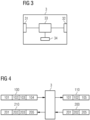
- Figure 3 shows a schematic representation of a device 3 for coupling a device network 4 with a communication network 2, as can be used, for example, in the previously described automation system.
- the device 3 can have a first interface 31, with which the device 3 can be connected to a device network 4.
- a second interface 32 can be provided, via which device 3 can be connected to the communication network 2.
- a processing device 33 is provided between the two interfaces 31, 32. The functionality of this processing device 33 is explained in more detail below.
- the device 3 receives a data telegram from an automation device 5-1, 5-2, with the concept of a device-specific identifier already being implemented in the corresponding automation device 5-1, 5-2, the device 3 forwards such a data telegram via the communication network 2 to the control device 1. Analogously, the device 3 can also forward data telegrams from the control device 1 to an automation device 5-1, 5-2 if the concept of the device-specific identifier is already implemented in this automation device 5-1, 5-2.
- the device 3 can first receive such a data telegram using a data telegram for such an automation device 5 -1, 5-2 verify the stored device-specific identifier and adapt the data telegram in such a way that it can be processed by the addressed automation device 5-1, 5-2.
- the device 3 can also receive a data telegram from an automation device 5-1, 5-2 and adapt such a data telegram using a device-specific identifier stored for this automation device 5-1, 5-2 and then send it to the control device 1 via the communication network 2 send.
- Figure 4 shows a schematic representation to illustrate the processing of data telegrams in a device 3 in the event that the concept of device-specific identifiers is not implemented in the corresponding automation device 5-1, 5-2.
- the top line shows the data exchange from the control device 1 to an automation device 5-1, 5-2.
- the bottom line shows the data exchange from an automation device 5-1, 5-2 to the control device 1.
- a data telegram 100 from the control device 1 can, for example, include, in addition to the user data 101, a status/control byte 102 and a data sequence 103 modified according to the device-specific identifier for the addressed automation device 5-1, 5-2.
- a checksum or a hash value 104 can be contained in the data telegram 100.
- the processing device 33 When receiving such a data telegram 100, the processing device 33 first checks the integrity of this data telegram using the checksum 104. If this checksum is not correct, the corresponding data telegram can be rejected. If the checksum is correct, the data telegram is modified using the device-specific identifier for the addressed automation device 5-1, 5-2. Here, for example, the data sequence 103 modified according to the device-specific identifier can be traced back to a data sequence from which the device-specific identifier has been removed. Thus, this data sequence can can be used to check correct addressing in the target automation device 5-1, 5-2.
- the device 3 then sends a data telegram 110 to the target automation device 5-1, 5-2, which, in addition to the user data 101 and the status/control byte 102, also contains the data sequence 105 freed from the device-specific identifier. If a correct device-specific identifier was used according to the addressing, the automation device 5-1, 5-2 can carry out a successful check based on this data sequence 105. If this check of the data sequence 105 fails, this can also be due to an addressing error. In this case, the automation device 5-1, 5-2 can reject this data telegram 110.
- the device 3 for coupling a device network with a communication network receives a data telegram from an automation device 5-1, 5-2 in which no device-specific identifier is implemented, this device-specific identifier can be supplemented by the device in 3 before such a data telegram is sent the control device 1 is sent.
- a data telegram 200 can, for example, include an additional data sequence 205 in addition to the user data 201 and a status/control byte 202.
- the processing device 33 of the device 3 can then determine a device-specific identifier for the automation device 5-1, 5-2 that sent such a data telegram and modify the data telegram 200 accordingly.
- the data sequence 205 can first be modified according to the device-specific identifier.
- a checksum or hash value 204 can be calculated.
- the processing device 33 can generate a data telegram 210, which, in addition to the user data 201, the status/control byte 202, includes the modified data sequence 205 in a further segment 203 and the checksum or the hash value in yet another segment 205.
- This Data telegram 210 can be sent to the control device 1 via the communication network 2.
- the respective data telegram can be signed using the device-specific identifier.
- a signature can also be checked using this device-specific identifier.
- an either-or operation (XOR) with the device-specific identifier can be applied to the data element to be signed. By applying such an XOR operation again with the same specific identifier, the original output data can then be obtained.
- the device-specific identifiers for automation device 5-1, 5-2 can be stored, for example, in a memory 34 of the device 3.
- the device-specific identifiers can be written into the memory 34 when the automation system is installed or configured by a user.
- any suitable automatic or semi-automatic methods for storing the device-specific identifier in the memory 34 of the device 3 are also possible.
- the control device 1 can transmit the device-specific identifiers to the device 3 via the communication network 2 using corresponding data packets.
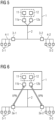
- Figure 5 shows a schematic representation of a schematic diagram of an automation system according to a further embodiment.
- the embodiment according to Figure 5 differs from the previously described embodiment of an automation system in particular in that the modification or signature of the data telegrams according to the device-specific identifier does not take place within the control processes 11, 12 in the control device 1. Rather, separate, outsourced processes 11a and 12a are provided in the control device 1, which are analogous to the operations the device 3 sign the data telegrams according to the device-specific identifiers or check the signatures according to the device-specific identifiers. This can be implemented, for example, using so-called sidecar containers.
- FIG. 6 a schematic representation of a basic diagram of an automation system according to yet another embodiment shows.
- This embodiment differs from the previously described embodiment in particular in that the data telegrams are generated within the control processes 11, 12 according to the device-specific identifiers.
- the data telegrams are then processed in separate, outsourced process modules 11b, 12b in the same way as was previously described in connection with the operations of the device 3 for coupling a device network to a communication network.
- the data telegrams modified in this way are then transmitted to devices 3a-1, 3a-2 via protected, preferably encrypted connections within the communication network 2.
- these devices can receive data telegrams from the automation devices 5-1, 5-2 via the protected connections within the communication network 2.
- the present invention relates to a system for verifying the addressing of components in an automation system with a hyper-converged infrastructure.
- a gateway is proposed which can add a device-specific signature to data telegrams if such a signature cannot be implemented by the automation device of the automation system itself.
Landscapes
- Engineering & Computer Science (AREA)
- Computer Networks & Wireless Communication (AREA)
- Signal Processing (AREA)
- Computer Security & Cryptography (AREA)
- Human Computer Interaction (AREA)
- Manufacturing & Machinery (AREA)
- Physics & Mathematics (AREA)
- General Physics & Mathematics (AREA)
- Automation & Control Theory (AREA)
- Data Exchanges In Wide-Area Networks (AREA)
- Communication Control (AREA)
Priority Applications (3)
| Application Number | Priority Date | Filing Date | Title |
|---|---|---|---|
| EP22182566.4A EP4300893B1 (fr) | 2022-07-01 | 2022-07-01 | Dispositif et procédé de couplage d'un réseau d'appareils et d'un réseau de communication, ainsi que système d'automatisation |
| US18/342,978 US20240019846A1 (en) | 2022-07-01 | 2023-06-28 | Apparatus, Automation System and Method for Coupling a Device Network and a Communication Network |
| CN202310813207.XA CN117336117A (zh) | 2022-07-01 | 2023-06-30 | 耦合设备网络和通信网络的装置和方法以及自动化系统 |
Applications Claiming Priority (1)
| Application Number | Priority Date | Filing Date | Title |
|---|---|---|---|
| EP22182566.4A EP4300893B1 (fr) | 2022-07-01 | 2022-07-01 | Dispositif et procédé de couplage d'un réseau d'appareils et d'un réseau de communication, ainsi que système d'automatisation |
Publications (3)
| Publication Number | Publication Date |
|---|---|
| EP4300893A1 true EP4300893A1 (fr) | 2024-01-03 |
| EP4300893C0 EP4300893C0 (fr) | 2025-10-22 |
| EP4300893B1 EP4300893B1 (fr) | 2025-10-22 |
Family
ID=83049943
Family Applications (1)
| Application Number | Title | Priority Date | Filing Date |
|---|---|---|---|
| EP22182566.4A Active EP4300893B1 (fr) | 2022-07-01 | 2022-07-01 | Dispositif et procédé de couplage d'un réseau d'appareils et d'un réseau de communication, ainsi que système d'automatisation |
Country Status (3)
| Country | Link |
|---|---|
| US (1) | US20240019846A1 (fr) |
| EP (1) | EP4300893B1 (fr) |
| CN (1) | CN117336117A (fr) |
Citations (3)
| Publication number | Priority date | Publication date | Assignee | Title |
|---|---|---|---|---|
| DE102013102998A1 (de) * | 2012-03-26 | 2013-09-26 | Fanuc Corporation | Sicherheitssignal-Bearbeitungssystem |
| EP3051779A1 (fr) * | 2015-01-29 | 2016-08-03 | Siemens Aktiengesellschaft | Procédé d'identification de liaison avec sécurité de fonctionnement et système de communication |
| WO2019141349A1 (fr) * | 2018-01-16 | 2019-07-25 | Nokia Technologies Oy | Système de communication |
-
2022
- 2022-07-01 EP EP22182566.4A patent/EP4300893B1/fr active Active
-
2023
- 2023-06-28 US US18/342,978 patent/US20240019846A1/en active Pending
- 2023-06-30 CN CN202310813207.XA patent/CN117336117A/zh active Pending
Patent Citations (3)
| Publication number | Priority date | Publication date | Assignee | Title |
|---|---|---|---|---|
| DE102013102998A1 (de) * | 2012-03-26 | 2013-09-26 | Fanuc Corporation | Sicherheitssignal-Bearbeitungssystem |
| EP3051779A1 (fr) * | 2015-01-29 | 2016-08-03 | Siemens Aktiengesellschaft | Procédé d'identification de liaison avec sécurité de fonctionnement et système de communication |
| WO2019141349A1 (fr) * | 2018-01-16 | 2019-07-25 | Nokia Technologies Oy | Système de communication |
Also Published As
| Publication number | Publication date |
|---|---|
| EP4300893C0 (fr) | 2025-10-22 |
| EP4300893B1 (fr) | 2025-10-22 |
| US20240019846A1 (en) | 2024-01-18 |
| CN117336117A (zh) | 2024-01-02 |
Similar Documents
| Publication | Publication Date | Title |
|---|---|---|
| EP3177973B1 (fr) | Procédé de fonctionnement d'un automate de sécurité et réseau d'automatisation ayant un tel automate de sécurité | |
| DE102018008674A1 (de) | Automatisierungsgerät mit integrierter Netzwerk-Analyse und Cloud-Anbindung | |
| WO2020108998A1 (fr) | Noeud de distribution, réseau d'automatisation et procédé de transmission de télégrammes | |
| EP3391157A1 (fr) | Coupleur de bus de terrain, système et procédé de configuration d'un module protégé contre les erreurs | |
| EP3051779A1 (fr) | Procédé d'identification de liaison avec sécurité de fonctionnement et système de communication | |
| EP4300893B1 (fr) | Dispositif et procédé de couplage d'un réseau d'appareils et d'un réseau de communication, ainsi que système d'automatisation | |
| EP2764665A1 (fr) | Procédé de communication redondante entre un terminal d'utilisateur et un serveur de système de gestion | |
| DE10360856A1 (de) | Bussystem für ein Flugzeug | |
| DE102019123146B4 (de) | Diagnose- und/oder parameterdaten-übertragung zwischen steuermodul und eingabe/ausgabe-modul | |
| WO2025131921A1 (fr) | Procédé d'initialisation d'un réseau d'automatisation, utilisateur de bus de remplacement et réseau d'automatisation | |
| WO2025103867A1 (fr) | Procédé pour déterminer une configuration d'abonnés de bus dans un réseau d'automatisation, et réseau d'automatisation | |
| DE102011082962A1 (de) | System und Verfahren zur Bereitstellung eines Steuerungsprogrammcodes | |
| DE10357422A1 (de) | Verfahren zur Übertragung von Daten über einen Datenbus sowie System und Gateway zur Durchführung des Verfahrens | |
| DE102021127310B4 (de) | System und Verfahren zur Datenübertragung | |
| DE102019110884A1 (de) | Verfahren zur Änderung einer Steuerungssoftware eines Automatisierungssystems | |
| LU102517B1 (de) | Verfahren zur Einbindung in eine Datenübertragung von einer Anzahl von an einer I/O-Station angeschlossenen I/O-Modulen, ein Stationskopf zur Ausführung eines solchen Verfahrens und ein System mit einem solchen Stationskopf | |
| DE102023112683A1 (de) | Station zum Einsatz in einem Feldnetz zwischen einem oder mehreren Feldgeräten und einer Zentraleinheit, sowie dazugehöriges Feldnetz | |
| EP3599525B1 (fr) | Procédé de communication sécurisée de données sur une machine-outil à commande numérique | |
| EP3869331A1 (fr) | Procédé d'ajustement des adresses f et module d'installations | |
| EP4073983B1 (fr) | Procédé de communication de données entre des participants d'un système d'automatisation | |
| DE102010039782A1 (de) | Verfahren zur Durchführung einer Kommunikation | |
| EP1885100B1 (fr) | Méthode d'attribution d'adresses à des terminaux de communication | |
| DE102011005239A1 (de) | Sicherheitssystem sowie Verfahren zum Austauschen von sicherheitsgerichteten Daten in einem Sicherheitssystem | |
| EP3979011A1 (fr) | Détermination d'un état de sécurité | |
| DE102024128267A1 (de) | Verfahren zum Übertragen eines Geräteberichts eines Feldgeräts sowie System |
Legal Events
| Date | Code | Title | Description |
|---|---|---|---|
| PUAI | Public reference made under article 153(3) epc to a published international application that has entered the european phase |
Free format text: ORIGINAL CODE: 0009012 |
|
| STAA | Information on the status of an ep patent application or granted ep patent |
Free format text: STATUS: THE APPLICATION HAS BEEN PUBLISHED |
|
| AK | Designated contracting states |
Kind code of ref document: A1 Designated state(s): AL AT BE BG CH CY CZ DE DK EE ES FI FR GB GR HR HU IE IS IT LI LT LU LV MC MK MT NL NO PL PT RO RS SE SI SK SM TR |
|
| STAA | Information on the status of an ep patent application or granted ep patent |
Free format text: STATUS: REQUEST FOR EXAMINATION WAS MADE |
|
| 17P | Request for examination filed |
Effective date: 20240702 |
|
| RBV | Designated contracting states (corrected) |
Designated state(s): AL AT BE BG CH CY CZ DE DK EE ES FI FR GB GR HR HU IE IS IT LI LT LU LV MC MK MT NL NO PL PT RO RS SE SI SK SM TR |
|
| GRAP | Despatch of communication of intention to grant a patent |
Free format text: ORIGINAL CODE: EPIDOSNIGR1 |
|
| STAA | Information on the status of an ep patent application or granted ep patent |
Free format text: STATUS: GRANT OF PATENT IS INTENDED |
|
| INTG | Intention to grant announced |
Effective date: 20250625 |
|
| GRAS | Grant fee paid |
Free format text: ORIGINAL CODE: EPIDOSNIGR3 |
|
| GRAA | (expected) grant |
Free format text: ORIGINAL CODE: 0009210 |
|
| STAA | Information on the status of an ep patent application or granted ep patent |
Free format text: STATUS: THE PATENT HAS BEEN GRANTED |
|
| AK | Designated contracting states |
Kind code of ref document: B1 Designated state(s): AL AT BE BG CH CY CZ DE DK EE ES FI FR GB GR HR HU IE IS IT LI LT LU LV MC MK MT NL NO PL PT RO RS SE SI SK SM TR |
|
| REG | Reference to a national code |
Ref country code: CH Ref legal event code: F10 Free format text: ST27 STATUS EVENT CODE: U-0-0-F10-F00 (AS PROVIDED BY THE NATIONAL OFFICE) Effective date: 20251022 Ref country code: GB Ref legal event code: FG4D Free format text: NOT ENGLISH |
|
| REG | Reference to a national code |
Ref country code: DE Ref legal event code: R096 Ref document number: 502022005825 Country of ref document: DE |
|
| REG | Reference to a national code |
Ref country code: IE Ref legal event code: FG4D Free format text: LANGUAGE OF EP DOCUMENT: GERMAN |
|
| U01 | Request for unitary effect filed |
Effective date: 20251022 |
|
| U07 | Unitary effect registered |
Designated state(s): AT BE BG DE DK EE FI FR IT LT LU LV MT NL PT RO SE SI Effective date: 20251028 |
|
| PG25 | Lapsed in a contracting state [announced via postgrant information from national office to epo] |
Ref country code: ES Free format text: LAPSE BECAUSE OF FAILURE TO SUBMIT A TRANSLATION OF THE DESCRIPTION OR TO PAY THE FEE WITHIN THE PRESCRIBED TIME-LIMIT Effective date: 20251022 |
|
| PG25 | Lapsed in a contracting state [announced via postgrant information from national office to epo] |
Ref country code: NO Free format text: LAPSE BECAUSE OF FAILURE TO SUBMIT A TRANSLATION OF THE DESCRIPTION OR TO PAY THE FEE WITHIN THE PRESCRIBED TIME-LIMIT Effective date: 20260122 |
|
| PG25 | Lapsed in a contracting state [announced via postgrant information from national office to epo] |
Ref country code: HR Free format text: LAPSE BECAUSE OF FAILURE TO SUBMIT A TRANSLATION OF THE DESCRIPTION OR TO PAY THE FEE WITHIN THE PRESCRIBED TIME-LIMIT Effective date: 20251022 |
|
| PG25 | Lapsed in a contracting state [announced via postgrant information from national office to epo] |
Ref country code: RS Free format text: LAPSE BECAUSE OF FAILURE TO SUBMIT A TRANSLATION OF THE DESCRIPTION OR TO PAY THE FEE WITHIN THE PRESCRIBED TIME-LIMIT Effective date: 20260122 |
|
| PG25 | Lapsed in a contracting state [announced via postgrant information from national office to epo] |
Ref country code: IS Free format text: LAPSE BECAUSE OF FAILURE TO SUBMIT A TRANSLATION OF THE DESCRIPTION OR TO PAY THE FEE WITHIN THE PRESCRIBED TIME-LIMIT Effective date: 20260222 |