EP4301954B1 - Tor mit einer funktionsfolie - Google Patents
Tor mit einer funktionsfolie Download PDFInfo
- Publication number
- EP4301954B1 EP4301954B1 EP22710040.1A EP22710040A EP4301954B1 EP 4301954 B1 EP4301954 B1 EP 4301954B1 EP 22710040 A EP22710040 A EP 22710040A EP 4301954 B1 EP4301954 B1 EP 4301954B1
- Authority
- EP
- European Patent Office
- Prior art keywords
- door leaf
- door
- functional film
- stabilizing device
- movement
- Prior art date
- Legal status (The legal status is an assumption and is not a legal conclusion. Google has not performed a legal analysis and makes no representation as to the accuracy of the status listed.)
- Active
Links
Images


Classifications
-
- E—FIXED CONSTRUCTIONS
- E06—DOORS, WINDOWS, SHUTTERS, OR ROLLER BLINDS IN GENERAL; LADDERS
- E06B—FIXED OR MOVABLE CLOSURES FOR OPENINGS IN BUILDINGS, VEHICLES, FENCES OR LIKE ENCLOSURES IN GENERAL, e.g. DOORS, WINDOWS, BLINDS, GATES
- E06B9/00—Screening or protective devices for wall or similar openings, with or without operating or securing mechanisms; Closures of similar construction
- E06B9/02—Shutters, movable grilles, or other safety closing devices, e.g. against burglary
- E06B9/08—Roll-type closures
- E06B9/11—Roller shutters
- E06B9/13—Roller shutters with closing members of one piece, e.g. of corrugated sheet metal
-
- E—FIXED CONSTRUCTIONS
- E06—DOORS, WINDOWS, SHUTTERS, OR ROLLER BLINDS IN GENERAL; LADDERS
- E06B—FIXED OR MOVABLE CLOSURES FOR OPENINGS IN BUILDINGS, VEHICLES, FENCES OR LIKE ENCLOSURES IN GENERAL, e.g. DOORS, WINDOWS, BLINDS, GATES
- E06B9/00—Screening or protective devices for wall or similar openings, with or without operating or securing mechanisms; Closures of similar construction
- E06B9/02—Shutters, movable grilles, or other safety closing devices, e.g. against burglary
- E06B9/08—Roll-type closures
- E06B9/11—Roller shutters
- E06B9/15—Roller shutters with closing members formed of slats or the like
-
- E—FIXED CONSTRUCTIONS
- E06—DOORS, WINDOWS, SHUTTERS, OR ROLLER BLINDS IN GENERAL; LADDERS
- E06B—FIXED OR MOVABLE CLOSURES FOR OPENINGS IN BUILDINGS, VEHICLES, FENCES OR LIKE ENCLOSURES IN GENERAL, e.g. DOORS, WINDOWS, BLINDS, GATES
- E06B9/00—Screening or protective devices for wall or similar openings, with or without operating or securing mechanisms; Closures of similar construction
- E06B9/02—Shutters, movable grilles, or other safety closing devices, e.g. against burglary
- E06B9/08—Roll-type closures
- E06B9/11—Roller shutters
- E06B9/13—Roller shutters with closing members of one piece, e.g. of corrugated sheet metal
- E06B2009/135—Horizontal shutter reinforcements
-
- E—FIXED CONSTRUCTIONS
- E06—DOORS, WINDOWS, SHUTTERS, OR ROLLER BLINDS IN GENERAL; LADDERS
- E06B—FIXED OR MOVABLE CLOSURES FOR OPENINGS IN BUILDINGS, VEHICLES, FENCES OR LIKE ENCLOSURES IN GENERAL, e.g. DOORS, WINDOWS, BLINDS, GATES
- E06B9/00—Screening or protective devices for wall or similar openings, with or without operating or securing mechanisms; Closures of similar construction
- E06B9/02—Shutters, movable grilles, or other safety closing devices, e.g. against burglary
- E06B9/08—Roll-type closures
- E06B9/11—Roller shutters
- E06B9/15—Roller shutters with closing members formed of slats or the like
- E06B2009/1505—Slat details
- E06B2009/1511—Coatings
-
- E—FIXED CONSTRUCTIONS
- E06—DOORS, WINDOWS, SHUTTERS, OR ROLLER BLINDS IN GENERAL; LADDERS
- E06B—FIXED OR MOVABLE CLOSURES FOR OPENINGS IN BUILDINGS, VEHICLES, FENCES OR LIKE ENCLOSURES IN GENERAL, e.g. DOORS, WINDOWS, BLINDS, GATES
- E06B9/00—Screening or protective devices for wall or similar openings, with or without operating or securing mechanisms; Closures of similar construction
- E06B9/02—Shutters, movable grilles, or other safety closing devices, e.g. against burglary
- E06B9/08—Roll-type closures
- E06B9/11—Roller shutters
- E06B9/15—Roller shutters with closing members formed of slats or the like
- E06B2009/1533—Slat connections
- E06B2009/155—Slats connected by separate elements
- E06B2009/1566—Rigid elements, e.g. hinges, hooks or profiles
Definitions
- the invention relates to a door, in particular a roller door, according to the preamble of patent claim 1.
- Such doors are realized, for example, as so-called roller doors, in which the door leaf forms a possibly multi-layered coil in the open position above the wall opening.
- the door leaf can have a number of door leaf segments arranged one behind the other in the direction of door leaf movement.
- At least one stabilizing device extending perpendicular to the door leaf movement, approximately horizontally or approximately perpendicular to the movement path, is arranged between two door leaf segments. The mutually facing edge regions of the door leaf segments, which extend approximately perpendicular to the movement path, are held on the stabilizing device.
- the door leaf segments When entering the open position and in the open position itself, the door leaf segments are deflected. This section of the track is also referred to as the deflection section.
- the door leaf segments are made of a flexible base material, such as polycarbonate, which allows the door leaf segments to bend following the deflection section.
- These door leaf segments also referred to as discs below, thus form bending areas of the door leaf, at least in the area between the stabilizing devices.
- the familiar roller shutters can also be used as so-called high-speed doors for closing industrial buildings.
- the stabilization of the door leaf movement by the stabilizing devices arranged between the individual door leaf segments, together with the flexible design of the door leaf segments themselves, enables door leaf speeds of 2 m/sec or more during opening and closing.
- Gates according to the preamble of patent claim 1 are in the DE 3609194 A1 and the DE 2707474 A1 described.
- the object of the invention is to provide doors with door leaves having bending areas, in particular roller doors, whose external appearance is hardly affected even in high-speed operation and under demanding weather conditions.
- This invention is based on the discovery that the hard coating successfully used in industrial sectional doors on a bending area subject to bending during door leaf movement leads to the formation of microcracks, which in many cases impair the external appearance more than the damage caused by door leaf movement without appropriate equipment in the bending areas and/or by weather influences.
- the dynamic loads regularly occurring in the deflection area during the opening and closing movement lead to the observed defects.
- a functional film i.e., a structurally coherent surface structure
- the structural properties of the functional film can be adjusted to accommodate the regular dynamic loads during door leaf operation.
- the films can be provided with appropriate deformability, In particular, they can be equipped with elastic deformability and/or extensibility, which can easily handle the alternating bending (stretching and compression) when passing through the deflection sections.
- a boundary layer can be formed between the base material and the functional film, which also withstands the occurring load changes without damage.
- the laminated film also counteracts noise development. This is evident, on the one hand, in the reduction of running noises generated during door leaf movement. On the other hand, a reduction in rattling noises can be observed when external pressure is applied to the door leaf in the closed position, particularly when a part of the door leaf that is in the bending area is mounted in a floating manner (see below). Furthermore, the laminated functional film can reduce noise emissions from a hall enclosed by the door leaf.
- the functional film laminated to the base material according to the invention can impart a desired external appearance to the door leaf in addition to or as an alternative to the improved resistance to impairments of the external appearance. If the priority in selecting the functional film is to avoid impairments of the external appearance, it is preferred within the scope of the invention if a boundary surface of the functional film facing away from the base material has a higher scratch resistance according to DIN EN ISO 12137 than the base material.
- the functional films can be designed to be transparent overall. However, the use of colored films is also conceivable, which can impart improved mechanical properties to the bending area in addition to the desired colorful impression.
- the functional films can be mixed with coloring pigments and/or equipped with corresponding translucent tints. They can be equipped with various types of filters or mirror coatings. In regions with high solar radiation, a mirrored film provides protection from sunlight while simultaneously allowing light to enter.
- a boundary surface of the functional film facing away from the base material can be at least partially mirrored and/or decorated with a pattern, such as a carbon-look, wood-look, or brushed aluminum pattern.
- a corresponding design freedom can hardly be realized in an economically viable manner by selecting the base materials for the bending area, because these base materials, such as polycarbonate sheets, can only be obtained with color pigments or special features in very large quantities, so that a design of the optical appearance via the starting material for the bending area is hardly economically viable.
- Functional films usable within the scope of the invention are available in a wide variety. If they have a thickness of 0.2 mm or less, in particular 0.15 mm or less, but at least 0.01 mm, preferably at least 0.04 mm, they can be laminated to the base material without significantly impairing the overall mass of the door leaf, but with sufficient mechanical stability to maintain the desired function.
- the functional film can be laminated to the base material using an adhesive, such as a pressure-sensitive acrylate adhesive.
- a suitable adhesive is characterized by sufficient elasticity while ensuring sufficient adhesion.
- the functional film can also be repositioned.
- the adhesive can be provided in the form of an adhesive layer of the functional film, which, after being laminated to the base material, forms a boundary layer between the base material and other film layers of the functional film.
- the base material itself is provided with the adhesive before lamination.
- the functional film can include a PVC layer.
- Functional films suitable for manufacturing the inventive gates which are already equipped with a pressure-sensitive acrylic adhesive as a precursor, are offered under the trade names 3M Wrap Film 2080 and 3M Scotchcal Film Clear View 8150. These functional films comprise a cast PVC layer and a layer of a pressure-sensitive acrylic adhesive.
- the cast PVC layer can have a layer thickness of 50 ⁇ m to 100 ⁇ m.
- the adhesive layer can have a thickness of less than 30 ⁇ m.
- the various functional films with a cast PVC layer and a pressure-sensitive acrylic adhesive are particularly advantageous in combination with a base material made of Polycarbonate is used.
- the door leaf preferably forms a multi-layer coil in the open position.
- 3M Obsidian Sun Protection Film comprises a clear first outer layer comprising polyethylene terephthalate (PET), a dye-added PET core layer comprising one or more dyes selected from the group consisting of Pigment Yellow 147, Pigment Red 177, Pigment Blue 60, Pigment Black 31, Pigment Red 149, and Pigment Red 122.
- the films further comprise a second outer layer comprising PET.
- the film is fade-resistant after exposure to 300 MJ/ m2 total irradiance integrated over the 259 nm to 385 nm band and time.
- the Obsidian solar control film may optionally be laminated to the base material using a pressure-sensitive acrylic adhesive.
- the door leaf comprises a plurality of door leaf elements arranged one behind the other in the direction of door leaf movement, at least one of which comprises a bending region, wherein at least one stabilizing device extending perpendicular to the direction of door leaf movement is arranged between two door leaf segments and the mutually facing edge regions of the door leaf segments are held on the stabilizing device and at least one edge region of at least one segment is held floatingly on the stabilizing device such that a relative movement of this edge region with respect to the stabilizing device is possible at least in the direction of door leaf movement. Impairment of the visual appearance of corresponding roller doors is reduced if the edge region of at least one segment, which can also be referred to as the bending region of this segment, is equipped with a functional film. In this case, the floating mounting can effectively reduce the abrasion marks in the edge region of the segment by means of the functional film.
- hinge arrangements can be provided to guide the door leaf movement on edges of the door leaf that run at least partially in the direction of gravity in the closed position and are fastened to the door leaf, each of which can have a plurality of hinge members that are articulated to one another with respect to hinge axes that run perpendicular to the lateral edges and approximately parallel to the plane of the door leaf.
- the space requirement in the open position is reduced by at least some of the segments of the door leaf being made of a flexible base material, such as a polycarbonate sheet, to provide bending areas. which, even in the open position, adapts to the coil to be formed, thus enabling a small spiral diameter in the open position.
- the segments of the known gates can be equipped with a functional foil.
- impairments of the segments occurring within the scope of this invention can already be reduced by using a functional film
- impairments can also be prevented by floating mounting of the door leaf segments with respect to the stabilizing device, without thereby impairing the overall stability of the entire construction.
- the floating mounting of the door leaf segments and the use of a functional film in the area of this floating mounting work synergistically to avoid visual impairments.
- stabilizing devices and any existing joint arrangements form a stable framework via which forces arising during the door leaf movement can be transmitted, without the need for rigid fastening of the door leaf segments, which may be provided with a functional coating, to the stabilizing devices in order to stabilize the overall arrangement. Therefore, a floating bearing, which allows a relative movement of the edge areas of the door leaf segments with respect to the stabilizing device, can be realized without impairing the door leaf movement or the stability of the entire door construction.
- the floating bearing allows for the absorption of any play or relative movements that may occur between the stabilising device and the door leaf segment during the door leaf movement, without causing damage or visual impairment to the door leaf construction due to excessive force.
- the visual impairment can be additionally counteracted by equipping the door leaf segments with a functional film.
- the floating bearing not only enables relative movement between the edge area of the door leaf segment and the stabilizing device in the direction of door leaf movement, but also, if necessary, in a direction parallel to the floating edge area or perpendicular to the direction of door leaf movement, so that even slight deviations of the door leaf movement from the specified path hardly cause damage to the door leaf segments.
- a synergistic effect can also be achieved here through the use of a functional film proposed by the invention.
- the relative movement of the floating edge region of at least one door leaf segment with respect to the stabilizing device is limited by means of a limiting arrangement, wherein the limiting arrangement becomes effective in particular in the case of a relative movement in a direction parallel to the direction of movement of the door leaf.
- the limiting arrangement has an extension of the floating edge region in a thickness direction running perpendicular to the door leaf plane spanned by the door leaf movement direction and the stabilizing device, and a receptacle formed in the stabilizing device for the extension of the edge region held floating thereon, wherein the receptacle has an opening penetrated by a transition region of the segment between the extension and a region of the segment exposed outside the stabilizing device, the width of which opening in the thickness direction is greater than the thickness of the transition region in the thickness direction, but smaller than the dimensions of the extension in the thickness direction.
- the stabilizing device is designed according to the WO 2018/219512 A1 expediently carried out by a stabilizing profile with a receiving area for receiving the extension of the edge area of the door leaf segment, wherein the receiving area of the stabilizing profile is adapted to the dimensions of the door leaf segment in such a way that the door leaf segment can be attached to the stabilizing profile.
- a further limitation of the relative movement of the edge area of the door leaf segment with respect to the stabilizing device or the stabilizing profile can be achieved if the support is limited by a floor on the side opposite the opening, whereby the distance between the opening of the support and the floor in the direction of door leaf movement is greater than the length of the extension of the floating edge area in the direction of door leaf movement.
- the difference in dimensions determines the possible play of the floating support of the edge area with respect to the stabilizing profile.
- the door leaf segment is formed from a web-like material, wherein the extension of the door leaf segment can be formed by bending the floating edge region with respect to a bending axis running parallel to the stabilizing device.
- the extension of the door leaf segment can be formed by bending the floating edge region with respect to a bending axis running parallel to the stabilizing device.
- no additional component is required to form the extension of the door leaf segment.
- the bending of the door leaf segment in the edge region running perpendicular to the direction of movement can be achieved, for example, by a roll-forming process.
- the edge region of the door leaf segment can be bent back on itself, for example in the manner of a hook, in order to thus obtain an extension of the floating edge region in the thickness direction.
- a method for producing a door according to the invention is essentially characterized by laminating a functional film onto a base material made of flexible material.
- the functional film can have an adhesive layer with which it is adhered to the base material.
- the functional film For lamination, the functional film, together with the base material, can pass through a nip formed between two rollers of a laminator.
- a laminator To prevent bubble formation during lamination of the functional film, it has proven advantageous to divert fluids from a boundary layer formed between the functional film and the base material through fluid channels in the functional film. These fluid channels can be provided in the adhesive layer of the functional film.
- the wall area of the door leaf segment is to be bent back onto itself in the manner of a hook as explained above, it has proven advantageous in the production of doors according to the invention if the functional film is laminated to a flexible base material in the form of a plastic sheet, preferably consisting at least partially of polycarbonate and/or SAN, and an edge of the plastic sheet equipped with the functional film is bent over along a bending line running parallel to this edge. If the segment prepared in this way is inserted into the stabilizing device, improved wear resistance can be achieved in the area of the floating bearing of the segment.
- the extension can be formed by a thickening of the edge region, in particular by gluing and/or welding a piping. Both the extension of the door leaf segment formed by bending the floating edge region and the extension formed by gluing and/or welding a piping can extend across the entire width of the door leaf. However, embodiments are also conceivable in which the extension extends only over part of the entire width of the door leaf.
- the extension can also be formed by individual extension elements applied to an edge of the door leaf segment, which are designed, for example, in the manner of clamp elements.
- Such extension clamps can be U-shaped components, which can be made, for example, from sheet metal.
- hook-shaped projections can be provided to create a positive connection between the extension clamps and the edge of the door leaf segment, which can be made, for example, from plastic, such as polycarbonate.
- the hook-shaped projections can also be designed as barbs.
- the stabilizing device has at least two releasably connected receiving parts, which form opposing boundaries of the opening.
- the edge region of the door leaf segment having the extension can first be connected to a boundary surface delimiting the opening.
- a first receiving part is placed in a direction perpendicular to the main surface of the door leaf segment or door leaf plane, and then the second receiving part, forming a further boundary surface of the opening, is added, whereby a positive connection between the two receiving parts is possible.
- the other receiving part can be clipped onto the first receiving part.
- the stabilizing device has two receptacles spaced apart in the direction of door leaf movement for receiving the facing edge regions of adjacent door leaf segments, it has proven particularly expedient if the upper receptacle in the closed position and the corresponding opening are delimited by two receptacle parts that are detachably connected to one another. In this case, an upper edge of a door leaf segment can be pushed into the lower receptacle of the stabilizing device in a direction parallel to the stabilizing device.
- the door leaf segment can then be threaded into a guide device of the roller shutter door and the lower edge of the door leaf segment can then be connected to a stabilizing device arranged underneath by first placing the lower edge of the door leaf segment against a boundary surface of the first receptacle part of the stabilizing device that delimits the opening and then attaching the second receptacle to the first receptacle part in a direction perpendicular to the door leaf plane to form the receptacle for the lower edge region of the door leaf segment.
- a sealing material is accommodated in at least one receptacle, preferably an upper receptacle of the stabilizing device, preferably in the area of the base of this receptacle.
- the sealing material can also be provided between the extension in the edge area of a door leaf segment and the opening of the receptacle.
- a sealing material arranged between the extension and the opening can hold the pane taut in position and reduce or completely prevent possible noise development when the door leaf segment moves relative to the stabilizing device.
- a suitable sealing material can be inserted into the receptacle of the stabilizing device or attached directly to the extension of the door leaf segment. This can be a sealing material that swells upon penetration of moisture. Since moisture can hardly penetrate into the lower receptacles in the closed position, sealing material is generally not required in these receptacles.
- the present invention It is particularly advantageously used in gates in which at least one segment having a floating edge section has at least one pane which is formed, at least in sections, from a flexible and/or transparent material, such as polycarbonate.
- At least one door leaf segment having a floating edge region has at least two panes that are spaced apart from one another in the direction of the door leaf thickness and run approximately parallel to one another, each of which has at least one edge region that is held on the stabilizing device and faces an adjacent door leaf segment, wherein at least one edge region of at least one pane is held floatingly on the stabilizing device in such a way that a relative movement of this edge region with respect to the stabilizing device is possible, at least in the direction of door leaf movement.
- This edge region can be held on the stabilizing device in a similar way to that already described above.
- at least one stabilizing device has two receptacles that are spaced apart from one another in the direction of the door leaf thickness, each for receiving an edge region of a pane of a door leaf segment.
- the panes of a door leaf segment are radially spaced from one another in the open position. They are moved along radially spaced paths into the open position and deform differently accordingly. This can potentially result in a brief collision when the door leaf is moved into the open position if the edge regions of the panes are identical and are accommodated in identical receptacles of the stabilizing device.
- a particularly preferred embodiment of the invention provides that at least one edge region of the inner (outer) pane facing (away from) the winding axis in the winding is held with greater play relative to the stabilizing device than the corresponding edge region of the outer (inner) pane facing (away from) the winding axis in the winding.
- the distance between the mouth of the receptacle for the edge region of the radially inner (outer) pane and the base of this receptacle in the direction of door leaf movement can be greater than the corresponding distance of the receptacle for the edge region of the radially outer (inner) panes. In this way, a possible difference in path (relative movement) can be compensated for by the different paths of the individual discs.
- the described double-pane arrangement creates an air cushion.
- the resulting chamber can be used in the area of the edges running parallel to the direction of door leaf movement of the panes are closed.
- a filling material can be provided in the area of at least one of the edges of at least one segment running parallel to the direction of movement of the door leaf, preferably between mutually facing boundary surfaces of the panes, which in a preferred embodiment of the invention can be made of a flexible material, such as an elastic rung.
- Elastic pads, such as foams, which are glued in or mechanically fixed, can be used as the filling material.
- the filling material thus also enables the necessary mobility when moving the door leaf into and out of the open position.
- fan-shaped plastic elements can be used as the filling material, which are connected to one another like a hinge and can be clipped onto a pane.
- the use of elastic pads or elastic fan elements for door leaf segments with only one pane is also contemplated in order to compensate for the offset between the pane and the reinforcement profile in the edge area. This allows a seal to be created with respect to the side part of the door. Since the door leaf segments of a door according to the invention are usually transparent at least in sections, it is particularly preferred within the scope of the invention if the filling material extends over 50% or less, in particular 20% or less, of the door leaf width in a direction parallel to the stabilizing devices, so that the transparency of the door leaf segments is only slightly impaired.
- At least one stabilizing device comprises at least two stabilizing elements spaced apart from one another in the direction of the door leaf thickness and connected to one another via a connecting element made of thermally insulating material.
- joint arrangements are preferably arranged in the area of the lateral edges of the door leaf, which in the closed position run at least partially in the direction of gravity, and are fastened to the door leaf to guide the door leaf movement, which can interact with corresponding fixed guide devices, such as guide rails, wherein each of the joint arrangements has a plurality of joint axes running perpendicular to the direction of movement or the lateral edges of the door leaf has hingedly connected joint members, so that the door leaf is connected to the joint arrangements via the stabilizing devices.
- the structure of the doors according to the invention corresponds to the structure of the WO 2018/219512 A1 described gates.
- At least one segment made of flexible material can be arranged between two stabilizing devices, wherein a lateral edge of the segment, which runs approximately perpendicular to the stabilizing devices and the hinge axes and approximately parallel to the hinge arrangements and the direction of movement of the gate leaf, can extend over two, three or more hinge members and at least one edge region of the segment can be held in a floating manner on a stabilizing device.
- At least one stabilizing device extends approximately parallel to a hinge axis and is connected along this hinge axis to at least two hinge arrangements, preferably to at least two hinge arrangements provided on opposite lateral door leaf edges.
- at least one reinforcement strip extending approximately parallel to the lateral door leaf edge or the door leaf movement direction and attached to the door leaf can be provided.
- At least one guide track which may be oval or spiral in shape, may be provided to guide the movement of the door leaf and to determine the opening position of the door leaf, wherein at least one joint member may have, on its side facing away from the door leaf, a guide arrangement which interacts with the guide track to guide the movement of the door leaf and which preferably comprises at least one guide roller which is rotatably mounted with respect to a roller axis running parallel to the joint axes and which is preferably received in a guide track at least in the opening position of the door leaf.
- an additional stabilizing device extending parallel to a hinge axis is connected only to the hinge arrangements.
- This embodiment of the invention makes it possible to vary the stabilization of the door leaf while maintaining the same design of the individual door leaf segments or panes, if the stabilizing device, which is only connected to the hinge arrangements, can be attached to the hinge arrangements regardless of the dimensions of the individual door leaf segments. It is not attached to the door leaf segments or panes.
- the attachment of this additional stabilizing device requires Therefore, no adjustment of the geometry of the door leaf segments or panels is required.
- the variability of the attachment of this stabilizing device is limited only by the pitch of the joint elements of the joint arrangement.
- the stabilizing device connected only to the hinge arrangements can be arranged between the lower stabilizing devices and those connected to the roller door panes.
- the stabilizing device not connected to the door leaf segments is arranged between the two upper stabilizing devices connected to the segments. In this way, a seal adapted to the height of the wall opening can be realized in the lintel area of the wall opening without having to change the geometry of the door leaf segments and the other components of the roller door according to the invention.
- the stabilizing device which is only connected to the hinge arrangements but not to the door leaf segments, has on its side facing away from the adjacent door leaf segment a sealing arrangement which can be placed on a lintel of the wall opening and/or has on its side facing the segment at least one sealing strip which extends approximately parallel to the hinge axes, preferably over substantially the entire door width, and which can be placed on the adjacent segment.
- the leading edge of the door leaf during an opening movement can be formed by a leading stabilizing device that is connected in a rotationally fixed manner to a segment made of a flexible material that is at the top edge of the segment in the closed position and that is connected in a rotationally fixed manner to a guide arrangement.
- a leading stabilizing device that is connected in a rotationally fixed manner to a segment made of a flexible material that is at the top edge of the segment in the closed position and that is connected in a rotationally fixed manner to a guide arrangement.
- a pretensioning device can be provided that can be coupled to a trailing edge of the door leaf during the opening movement and pretensioned during the opening movement to brake the opening movement and to provide a pretensioning force that urges the door leaf from the open position into the closed position.
- a door according to the invention expediently has a guide device for guiding the door leaf movement between the open position and the closed position.
- the invention is used with particular advantage in doors that enable high door running speeds.
- the guide device can enable contactless magnetic guidance.
- the guide device can have a magnetic field generating device on the door leaf side and a magnetic field generating device that is fixed with respect to the wall opening, wherein the magnetic field generating devices are designed to achieve contactless guidance of the door leaf movement along at least a section of the predetermined path in the region of at least one of the opposing lateral edges.
- the guide arrangement has at least one guide web which is fixedly arranged with respect to the wall opening and extends along a section of the predetermined path, said guide web having two outer boundary surfaces and at least two guide devices fastened to the door leaf, wherein a first outer boundary surface of the guide web forms a guide surface for a first guide device and a second outer boundary surface of the guide web forms a second guide surface for a guide device, such that the guide web is received between the guide devices fastened to the door leaf.
- At least one guide device can have a guide roller which is rotatably mounted with respect to a roller axis which runs perpendicular to the predetermined path and, in the closed position, approximately parallel to the door leaf and which rolls on a guide surface of the door leaf when the door leaf moves.
- At least one magnetic field generating device preferably at least one door leaf-side magnetic field generating device, can have at least one permanent magnet.
- the door leaf-side magnetic field generating device can expediently have two permanent magnets arranged on opposite sides of the guide web, which are attached to a common support that spans a door leaf-side edge of the guide web. Further details of the magnetic field generating devices are described in the WO 2019/192976 A1 explained.
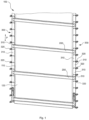
- Fig. 1 shows two door leaf segments 110 and 120 of a door leaf 100 of a door according to the invention, arranged one behind the other in the direction of door leaf movement indicated by the double arrow P.
- the door leaf segments consist at least partially of a flexible material and form bending regions of the door leaf.
- At least one door leaf segment, preferably each door leaf segment, can be equipped with a functional film on at least part of its outer boundary surface.
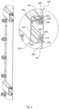
- a stabilizing device designed as a stabilizing profile 200 is arranged between the door leaf segments 110 and 120. The stabilizing profile 200 extends in a direction perpendicular to the direction of door leaf movement P, approximately in the plane of the door leaf.
- An upper edge of the door leaf segment 120 is held on a further stabilizing profile 200, just as a lower edge of the door leaf segment 110 is also held on a lower stabilizing profile 200.
- the stabilizing profiles 200 are attached to a joint arrangement 300 extending approximately parallel to the direction of door leaf movement or parallel to a lateral edge of the door leaf 100.
- the joint arrangement 300 comprises a plurality of joint members 310 arranged one behind the other in the direction of door leaf movement and connected to one another in an articulated manner with respect to joint axes running perpendicular to the direction of door leaf movement P.
- Three joint members 310 are arranged between each two adjacent stabilizing profiles 200. In other embodiments of the invention, only one or two or four or more joint members can be provided between the stabilizing profiles 200.
- a stabilizing profile can also be provided in the region of each connection between successive joint members.
- the hinge assembly has guide rollers 320 on its side facing away from the door leaf segments 110 and 120, which are rotatably mounted with respect to roller axes running parallel to the hinge axes.
- the guide rollers 320 are arranged in pairs in the region of a hinge axis in such a way that they can accommodate a guide web between them and can roll on opposing boundary surfaces of the guide web, thus enabling guidance of the door leaf movement, as in the PCT/EP2019/058221 described.
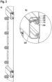
- an upper edge region 112 of the door leaf segment 110 extending parallel to the joint axes and parallel to the stabilizing profile 200 is arranged in a receptacle 240 of the stabilizing profile 200.
- the upper edge 112 of the door leaf segment 110 is designed by bending the upper edge of the door leaf segment 112 onto itself as an extension in a door leaf plane perpendicular to the door leaf plane determined by the door leaf movement direction P and the stabilizing profile 200. Starting from the extension 112, the door leaf segment 110 extends downwards with a transition region through an opening 250 of the stabilizing profile 200 and is exposed outside the opening 250, as shown in Fig. 1 can be seen.
- the door leaf segment 120 has an extension 122 accommodated in a receptacle 230 of the stabilizing profile 200. Starting from the extension 122, the door leaf segment 120 extends upwards with a transition region through an opening 225 and is exposed outside the opening 225.
- the opening 250 is delimited by boundary surfaces 232 and 242, the distance between which in a direction parallel to the door leaf thickness direction is less than the thickness of the extension 112, but greater than the thickness of the transition region of the door leaf segment 110 between the extension 112 and the area exposed outside the stabilizing profile 200.
- the opening 225 is delimited by boundary surfaces 212 and 222, the distance in the door leaf thickness direction being less than the thickness of the extension 122, but greater than the thickness of a transition region between the extension 122 and the region of the door leaf segment 120 exposed outside the stabilizing profile 200.
- the stabilizing profile 200 is designed in two parts, consisting of two detachably connected parts 210 and 220.
- the recess 240 at the lower edge of the stabilizing profile 200 is formed entirely by the first stabilizing profile part 210, while the receptacle 230 at the upper edge of the stabilizing profile 200 is formed by the two stabilizing profile parts 210 and 220.
- a first boundary surface 212 of the mouth 225 is formed by the first stabilizing profile part 210, while a second boundary surface 222 of the receptacle 230 is formed by the second stabilizing profile part 220.
- an upper edge of a shutter leaf segment can be inserted into the receptacle 240 in a direction parallel to the stabilizing profile 200, with a transition region between the extension 240 and a region of the shutter leaf segment exposed outside the stabilizing profile 200 passing through the opening 250.
- the module thus prepared can be threaded into a guide device, which can consist of a guide web arranged between the guide rollers 320.
- a lower edge 122 of the door leaf segment can be placed against a boundary surface 212 of the first stabilizing profile part 210 and the second stabilizing profile 220 can be clipped onto the first stabilizing profile 210 to form the mouth 225, which is penetrated by the transition region between an extension of the door leaf segment received in the receptacle 230 and a region of the door leaf segment exposed outside the stabilizing profile 200.
- the distance between the opposing boundary surfaces 212 and 222, or 232 and 242, of the orifices 225 and 250, respectively, is greater than the thickness of the transition areas penetrating these orifices. This prevents a clamping effect in the transition areas.
- the distance between the opening 225 or 250 and the bottoms of the receptacles 230 and 240 opposite the corresponding openings 225 or 250 is greater than the length of the extensions 122 or 112 in the direction of door leaf movement. This enables a relative movement of the door leaf segments 110 and 120 with respect to the stabilizing profile 200.
- a sealing material can be arranged, which may swell if moisture penetrates.
- a damping element 230 is arranged between the bent lower edge of the disc 120 forming the extension 122 and the lower boundary surface of the part 220 of the stabilizing profile 200.
- This damping element 230 seals the disc 120 floatingly mounted in the stabilizing profile 200, and on the other hand, preloads the disc 120 floatingly mounted in the stabilizing profile 200, helps compensate for tolerances, and holds the disc 120 taut in its position.
- the damping element 140 reduces noise that can occur when the bent lower edge of the disc 120 is moved in the receptacle 230 and strikes the lower boundary surface of the part 220 of the stabilizing profile.
- the door leaf segments comprise two panes 120a and 120b, or 110a and 110b, which run essentially parallel to one another and are each designed as flexible polycarbonate panes.
- the lower edges of the panes 120a and 120b are each provided with an extension formed by bending these edges, which are mounted in a floating manner in receptacles 230a and 230b of the stabilizing profile 1200.
- the upper edges of the panes 110a and 110b of the lower segment are held in receptacles 240a and 240b of the stabilizing profile 1200.
- An air cushion 180 which promotes thermal insulation, is formed between the panes 120a and 120b, or 110a and 110b.
- the air cushion 180 is closed at the edges running parallel to the direction of movement P of the segments 120 and 110 by elastic pads 190 provided between the discs 120a and 120b or 110a and 110b.
- These pads 190 can be designed as elastic bars.
- elastic pads made of a foam material can be used, which are glued in or mechanically fixed.
- the elastic design of the pads 190 also allows the necessary mobility when wrapping the door leaf into the spiral guide track when reaching the opening position.
- fan-shaped plastic elements which are connected to each other like hinges, can be clipped onto the pane in the chamber 180.
- the screws shown are designed to compensate for the offset between the pane and the stabilizing profile in the wall area. This can improve the sealing of the door leaf in the closed position.
- the embodiment of the invention shown differs essentially from that shown in the Fig. 4 explained embodiment, the chamber 2230b of the stabilizing profile 2200, which serves to receive the extension 230b at the lower edge of the disc 110b, has a greater depth in the direction of door leaf movement than the chamber 230a, which serves to receive the extension 122a formed at the lower edge of the disc 110a.
- the stabilizing profiles 3200 are constructed in three parts overall, with parts 3210, 3220, 3230 being constructed consecutively in the direction of the door leaf thickness.
- the part 3210 which is located inside in the closed position of the door leaf, as is the part 3220 of the stabilizing profile 3200, which is located outside in the closed position, is made of a metallic material. This gives the stabilizing profile the necessary stability.
- the parts 3210 and 3220 are connected to one another via connecting elements 3230 made of thermally insulating material, such as plastic.
- a stabilizing profile 400 is provided between the stabilizing profiles 200 fixed to the lower and upper edges of the panes 110, 120, which is fastened exclusively to the joint members of the joint arrangement 300.
- This additional stabilizing profile 400 can be positioned independently of the pane geometry and can be attached to position a lintel seal depending on the height of the wall opening.
- the stabilizing profile 400 is equipped with a sealing element 410 on its side facing away from the panes 110, 120, while on the side facing the pane 120 it is designed with hose seals 420 that rest against the pane 120.
- the additional stabilizing profile 400 is not fastened to the pane 120, it can be fastened to any joint members 310 regardless of the pane geometry.
- the position of the seal 410 can thus be adapted to the height of the wall opening. This not only improves the sealing effect but also increases the overall stability of the roller shutter.
- the invention is not limited to the exemplary embodiment explained with reference to the drawing.
- the extensions in the area of the edges of the door leaf segments can also be formed by glued or welded piping.
- the stabilizing profiles 200 can be designed as a single piece, so that the extended edges of the door leaf segments must be inserted laterally into the stabilizing profiles.
- guide arrangements in which guide rollers are accommodated in a guide rail can also be used.
- a contactless magnetic guide can also be used.
- the functional films used according to the invention can also comprise so-called low-E films with a high degree of reflection. This allows good thermal insulation to be achieved with a comparatively thin pane thickness.
- the stabilizing devices of doors according to the invention can also be covered with film to enable a uniform door leaf design.
Landscapes
- Engineering & Computer Science (AREA)
- Structural Engineering (AREA)
- Architecture (AREA)
- Civil Engineering (AREA)
- Securing Of Glass Panes Or The Like (AREA)
- Laminated Bodies (AREA)
Priority Applications (1)
| Application Number | Priority Date | Filing Date | Title |
|---|---|---|---|
| HRP20250973TT HRP20250973T1 (hr) | 2021-03-05 | 2022-03-02 | Vrata s funkcionalnim filmom |
Applications Claiming Priority (2)
| Application Number | Priority Date | Filing Date | Title |
|---|---|---|---|
| DE102021105368.4A DE102021105368A1 (de) | 2021-03-05 | 2021-03-05 | Tor |
| PCT/EP2022/055259 WO2022184766A1 (de) | 2021-03-05 | 2022-03-02 | Tor mit einer funktionsfolie |
Publications (3)
| Publication Number | Publication Date |
|---|---|
| EP4301954A1 EP4301954A1 (de) | 2024-01-10 |
| EP4301954B1 true EP4301954B1 (de) | 2025-06-18 |
| EP4301954C0 EP4301954C0 (de) | 2025-06-18 |
Family
ID=80738934
Family Applications (1)
| Application Number | Title | Priority Date | Filing Date |
|---|---|---|---|
| EP22710040.1A Active EP4301954B1 (de) | 2021-03-05 | 2022-03-02 | Tor mit einer funktionsfolie |
Country Status (7)
| Country | Link |
|---|---|
| US (1) | US20240229550A9 (pl) |
| EP (1) | EP4301954B1 (pl) |
| DE (1) | DE102021105368A1 (pl) |
| HR (1) | HRP20250973T1 (pl) |
| HU (1) | HUE072691T2 (pl) |
| PL (1) | PL4301954T3 (pl) |
| WO (1) | WO2022184766A1 (pl) |
Families Citing this family (1)
| Publication number | Priority date | Publication date | Assignee | Title |
|---|---|---|---|---|
| DE102019125204A1 (de) * | 2019-09-19 | 2021-03-25 | Seuster Kg | Rolltor |
Family Cites Families (17)
| Publication number | Priority date | Publication date | Assignee | Title |
|---|---|---|---|---|
| DE1985411U (de) | 1967-12-28 | 1968-05-16 | Kalle Ag | Rolladen, insbesondere fuer moebel. |
| DE2707474A1 (de) * | 1977-02-21 | 1978-08-24 | Alten K | Verschlusskoerper fuer rolltore o.dgl. |
| DE3609194A1 (de) * | 1986-03-19 | 1987-09-24 | Guenther Becker | Tuerblatt aus weich-pvc sowie rolltor mit einem solchen |
| DE3733778A1 (de) * | 1987-10-06 | 1989-04-27 | Erich Doering | Bogenfoermig verschiebbares schiebetor |
| US6331343B1 (en) * | 1999-05-07 | 2001-12-18 | 3M Innovative Properties Company | Films having a fibrillated surface and method of making |
| DE19934611C2 (de) | 1999-07-23 | 2002-03-28 | Kautex Textron Gmbh & Co Kg | Kunststoffplatten für Streifenvorhänge und Tore |
| DE10236648B4 (de) * | 2002-08-09 | 2011-11-17 | Efaflex Tor- Und Sicherheitssysteme Gmbh & Co. Kg | Schnellaufendes Industrietor mit flexiblem Behang |
| DE102009058641A1 (de) | 2008-12-18 | 2010-06-24 | Torsten Ruhe | Garagetor |
| DE202013005164U1 (de) * | 2013-06-06 | 2013-07-30 | Seuster Kg | Tor |
| US20160145938A1 (en) | 2013-06-18 | 2016-05-26 | Hunter Douglas Inc. | Covering for an architectural opening having coved slats |
| CN106061729A (zh) * | 2014-03-07 | 2016-10-26 | 3M创新有限公司 | 耐久性挤出型染色聚酯膜 |
| AU2017372889A1 (en) * | 2016-12-09 | 2019-06-27 | B&D Australia Pty Ltd | Decorative facade for garage doors |
| JP6946471B2 (ja) * | 2017-05-31 | 2021-10-06 | ゾイスター コマンデイトゲゼルシャフト | ロールアップドア |
| DE102017118959A1 (de) * | 2017-08-18 | 2019-02-21 | Seuster Kg | Tor, insbesondere Spiraltor |
| SI3775463T1 (sl) | 2018-04-05 | 2024-04-30 | Seuster Kg | Vrata, obsegajoča ureditev za vodenje |
| EP3814600A4 (en) * | 2018-06-27 | 2022-03-23 | Auto Mossa Holdings Limited | Thermal barrier roller door assemblies and parts thereof |
| DE102019125204A1 (de) * | 2019-09-19 | 2021-03-25 | Seuster Kg | Rolltor |
-
2021
- 2021-03-05 DE DE102021105368.4A patent/DE102021105368A1/de active Pending
-
2022
- 2022-03-02 HR HRP20250973TT patent/HRP20250973T1/hr unknown
- 2022-03-02 PL PL22710040.1T patent/PL4301954T3/pl unknown
- 2022-03-02 EP EP22710040.1A patent/EP4301954B1/de active Active
- 2022-03-02 WO PCT/EP2022/055259 patent/WO2022184766A1/de not_active Ceased
- 2022-03-02 HU HUE22710040A patent/HUE072691T2/hu unknown
- 2022-03-02 US US18/546,861 patent/US20240229550A9/en active Pending
Also Published As
| Publication number | Publication date |
|---|---|
| HRP20250973T1 (hr) | 2025-10-10 |
| HUE072691T2 (hu) | 2025-12-28 |
| EP4301954A1 (de) | 2024-01-10 |
| US20240229550A9 (en) | 2024-07-11 |
| PL4301954T3 (pl) | 2025-10-06 |
| US20240133234A1 (en) | 2024-04-25 |
| WO2022184766A1 (de) | 2022-09-09 |
| DE102021105368A1 (de) | 2022-09-08 |
| EP4301954C0 (de) | 2025-06-18 |
Similar Documents
| Publication | Publication Date | Title |
|---|---|---|
| EP0110221B1 (de) | Polycarbonat-Kunststofftafel | |
| EP0124828B1 (de) | Vorrichtung zur Wärmedämmung und Klimatisierung | |
| EP0323445B1 (de) | Rolltor | |
| DE60205958T2 (de) | Herstellungsverfahren und Vorrichtung eines lamellierten Sprossenprofiles | |
| DE102009011265B4 (de) | Ganzglasdach für ein Kraftfahrzeug | |
| DE3043973A1 (de) | Verfahren zur herstellung einer isolierglaseinheit | |
| DE4427402A1 (de) | Konstruktionselement aus einer Glasscheibe und einem mit der Glasscheibe verklebten Holm oder Rahmen | |
| EP3805513B1 (de) | Rolltor | |
| EP3889385A1 (de) | Profil für ein fenster- und/oder türteil mit metalllage mit faserlage | |
| EP4234875B1 (de) | Rolltor | |
| EP0162937B1 (de) | Kunststoff-Profilleiste | |
| EP3034735B1 (de) | Schiebewandsystem mit mindestens einem Türflügelelement mit einer Glasscheibe und Verfahren zum Befestigen der Glasscheibe im Schiebewandsystem | |
| EP4301954A1 (de) | Tor mit einer funktionsfolie | |
| WO2008083778A1 (de) | Rolltor, insbesondere schnell laufendes industrietor, sowie lamelle hierfür und verfahren zu ihrer herstellung | |
| DE20304015U1 (de) | Vorrichtung zum Verbessern der wärmetechnischen Eigenschaften von lichtdurchlässigen Gebäudeteilen | |
| DE3444853A1 (de) | Rolltor | |
| EP1191183A2 (de) | Isolierglasanordnung mit Folien-Rollo | |
| DE202014000533U1 (de) | Isolationsvorrichtung für Fenster oder Fassaden | |
| EP1812675B1 (de) | Hohlkammerprofil aus thermoplastischem kunststoff | |
| EP0358920B1 (de) | Rolltorbehang | |
| DE19918698A1 (de) | Verfahren zur Herstellung eines Metallfolien-/Gewebeverbundes insbesondere für Rolladenpanzer | |
| WO2008138417A1 (de) | Rolltor, insbesondere schnell laufendes industrietor, sowie lamelle hierfür und verfahren zu ihrer herstellung | |
| DE29607921U1 (de) | Aufrollbares Wandelement aus Glasleisten | |
| EP3034739A1 (de) | Schiebewandsystem mit optimierter Dichtung | |
| EP3034742A1 (de) | Schiebewandsystem mit geringstem Anschubmoment |
Legal Events
| Date | Code | Title | Description |
|---|---|---|---|
| STAA | Information on the status of an ep patent application or granted ep patent |
Free format text: STATUS: UNKNOWN |
|
| STAA | Information on the status of an ep patent application or granted ep patent |
Free format text: STATUS: THE INTERNATIONAL PUBLICATION HAS BEEN MADE |
|
| PUAI | Public reference made under article 153(3) epc to a published international application that has entered the european phase |
Free format text: ORIGINAL CODE: 0009012 |
|
| STAA | Information on the status of an ep patent application or granted ep patent |
Free format text: STATUS: REQUEST FOR EXAMINATION WAS MADE |
|
| 17P | Request for examination filed |
Effective date: 20230822 |
|
| AK | Designated contracting states |
Kind code of ref document: A1 Designated state(s): AL AT BE BG CH CY CZ DE DK EE ES FI FR GB GR HR HU IE IS IT LI LT LU LV MC MK MT NL NO PL PT RO RS SE SI SK SM TR |
|
| DAV | Request for validation of the european patent (deleted) | ||
| DAX | Request for extension of the european patent (deleted) | ||
| GRAP | Despatch of communication of intention to grant a patent |
Free format text: ORIGINAL CODE: EPIDOSNIGR1 |
|
| STAA | Information on the status of an ep patent application or granted ep patent |
Free format text: STATUS: GRANT OF PATENT IS INTENDED |
|
| INTG | Intention to grant announced |
Effective date: 20241112 |
|
| GRAJ | Information related to disapproval of communication of intention to grant by the applicant or resumption of examination proceedings by the epo deleted |
Free format text: ORIGINAL CODE: EPIDOSDIGR1 |
|
| STAA | Information on the status of an ep patent application or granted ep patent |
Free format text: STATUS: REQUEST FOR EXAMINATION WAS MADE |
|
| GRAP | Despatch of communication of intention to grant a patent |
Free format text: ORIGINAL CODE: EPIDOSNIGR1 |
|
| STAA | Information on the status of an ep patent application or granted ep patent |
Free format text: STATUS: GRANT OF PATENT IS INTENDED |
|
| INTC | Intention to grant announced (deleted) | ||
| INTG | Intention to grant announced |
Effective date: 20250114 |
|
| GRAS | Grant fee paid |
Free format text: ORIGINAL CODE: EPIDOSNIGR3 |
|
| GRAA | (expected) grant |
Free format text: ORIGINAL CODE: 0009210 |
|
| STAA | Information on the status of an ep patent application or granted ep patent |
Free format text: STATUS: THE PATENT HAS BEEN GRANTED |
|
| AK | Designated contracting states |
Kind code of ref document: B1 Designated state(s): AL AT BE BG CH CY CZ DE DK EE ES FI FR GB GR HR HU IE IS IT LI LT LU LV MC MK MT NL NO PL PT RO RS SE SI SK SM TR |
|
| REG | Reference to a national code |
Ref country code: GB Ref legal event code: FG4D Free format text: NOT ENGLISH |
|
| REG | Reference to a national code |
Ref country code: CH Ref legal event code: EP |
|
| REG | Reference to a national code |
Ref country code: DE Ref legal event code: R096 Ref document number: 502022004323 Country of ref document: DE |
|
| REG | Reference to a national code |
Ref country code: CH Ref legal event code: EP |
|
| REG | Reference to a national code |
Ref country code: IE Ref legal event code: FG4D Free format text: LANGUAGE OF EP DOCUMENT: GERMAN |
|
| U01 | Request for unitary effect filed |
Effective date: 20250715 |
|
| U07 | Unitary effect registered |
Designated state(s): AT BE BG DE DK EE FI FR IT LT LU LV MT NL PT RO SE SI Effective date: 20250721 |
|
| REG | Reference to a national code |
Ref country code: HR Ref legal event code: T1PR Ref document number: P20250973 Country of ref document: HR |
|
| PG25 | Lapsed in a contracting state [announced via postgrant information from national office to epo] |
Ref country code: GR Free format text: LAPSE BECAUSE OF FAILURE TO SUBMIT A TRANSLATION OF THE DESCRIPTION OR TO PAY THE FEE WITHIN THE PRESCRIBED TIME-LIMIT Effective date: 20250919 |
|
| PG25 | Lapsed in a contracting state [announced via postgrant information from national office to epo] |
Ref country code: RS Free format text: LAPSE BECAUSE OF FAILURE TO SUBMIT A TRANSLATION OF THE DESCRIPTION OR TO PAY THE FEE WITHIN THE PRESCRIBED TIME-LIMIT Effective date: 20250918 |
|
| REG | Reference to a national code |
Ref country code: HU Ref legal event code: AG4A Ref document number: E072691 Country of ref document: HU |
|
| PG25 | Lapsed in a contracting state [announced via postgrant information from national office to epo] |
Ref country code: IS Free format text: LAPSE BECAUSE OF FAILURE TO SUBMIT A TRANSLATION OF THE DESCRIPTION OR TO PAY THE FEE WITHIN THE PRESCRIBED TIME-LIMIT Effective date: 20251018 |
|
| PG25 | Lapsed in a contracting state [announced via postgrant information from national office to epo] |
Ref country code: SM Free format text: LAPSE BECAUSE OF FAILURE TO SUBMIT A TRANSLATION OF THE DESCRIPTION OR TO PAY THE FEE WITHIN THE PRESCRIBED TIME-LIMIT Effective date: 20250618 |
|
| PG25 | Lapsed in a contracting state [announced via postgrant information from national office to epo] |
Ref country code: SK Free format text: LAPSE BECAUSE OF FAILURE TO SUBMIT A TRANSLATION OF THE DESCRIPTION OR TO PAY THE FEE WITHIN THE PRESCRIBED TIME-LIMIT Effective date: 20250618 |
|
| PG25 | Lapsed in a contracting state [announced via postgrant information from national office to epo] |
Ref country code: ES Free format text: LAPSE BECAUSE OF FAILURE TO SUBMIT A TRANSLATION OF THE DESCRIPTION OR TO PAY THE FEE WITHIN THE PRESCRIBED TIME-LIMIT Effective date: 20250618 |
|
| REG | Reference to a national code |
Ref country code: CH Ref legal event code: U11 Free format text: ST27 STATUS EVENT CODE: U-0-0-U10-U11 (AS PROVIDED BY THE NATIONAL OFFICE) Effective date: 20260401 |
|
| PGFP | Annual fee paid to national office [announced via postgrant information from national office to epo] |
Ref country code: GB Payment date: 20260324 Year of fee payment: 5 |
|
| PGFP | Annual fee paid to national office [announced via postgrant information from national office to epo] |
Ref country code: NO Payment date: 20260320 Year of fee payment: 5 |
|
| PGFP | Annual fee paid to national office [announced via postgrant information from national office to epo] |
Ref country code: HU Payment date: 20260330 Year of fee payment: 5 |
|
| PGFP | Annual fee paid to national office [announced via postgrant information from national office to epo] |
Ref country code: CZ Payment date: 20260320 Year of fee payment: 5 |
|
| PGFP | Annual fee paid to national office [announced via postgrant information from national office to epo] |
Ref country code: PL Payment date: 20260320 Year of fee payment: 5 |
|
| PLBE | No opposition filed within time limit |
Free format text: ORIGINAL CODE: 0009261 |
|
| STAA | Information on the status of an ep patent application or granted ep patent |
Free format text: STATUS: NO OPPOSITION FILED WITHIN TIME LIMIT |
|
| REG | Reference to a national code |
Ref country code: CH Ref legal event code: L10 Free format text: ST27 STATUS EVENT CODE: U-0-0-L10-L00 (AS PROVIDED BY THE NATIONAL OFFICE) Effective date: 20260430 |
|
| U20 | Renewal fee for the european patent with unitary effect paid |
Year of fee payment: 5 Effective date: 20260330 |
|
| REG | Reference to a national code |
Ref country code: HR Ref legal event code: ODRP Ref document number: P20250973 Country of ref document: HR Payment date: 20260331 Year of fee payment: 5 |