EP4303149B1 - Bouchon imperdable présentant un angle d'ouverture stabilisé - Google Patents
Bouchon imperdable présentant un angle d'ouverture stabilisé Download PDFInfo
- Publication number
- EP4303149B1 EP4303149B1 EP23211240.9A EP23211240A EP4303149B1 EP 4303149 B1 EP4303149 B1 EP 4303149B1 EP 23211240 A EP23211240 A EP 23211240A EP 4303149 B1 EP4303149 B1 EP 4303149B1
- Authority
- EP
- European Patent Office
- Prior art keywords
- closure
- cap
- bottle neck
- screw cap
- separating web
- Prior art date
- Legal status (The legal status is an assumption and is not a legal conclusion. Google has not performed a legal analysis and makes no representation as to the accuracy of the status listed.)
- Active
Links
Images


Classifications
-
- B—PERFORMING OPERATIONS; TRANSPORTING
- B65—CONVEYING; PACKING; STORING; HANDLING THIN OR FILAMENTARY MATERIAL
- B65D—CONTAINERS FOR STORAGE OR TRANSPORT OF ARTICLES OR MATERIALS, e.g. BAGS, BARRELS, BOTTLES, BOXES, CANS, CARTONS, CRATES, DRUMS, JARS, TANKS, HOPPERS, FORWARDING CONTAINERS; ACCESSORIES, CLOSURES, OR FITTINGS THEREFOR; PACKAGING ELEMENTS; PACKAGES
- B65D41/00—Caps, e.g. crown caps or crown seals, i.e. members having parts arranged for engagement with the external periphery of a neck or wall defining a pouring opening or discharge aperture; Protective cap-like covers for closure members, e.g. decorative covers of metal foil or paper
- B65D41/32—Caps or cap-like covers with lines of weakness, tearing-strips, tags, or like opening or removal devices, e.g. to facilitate formation of pouring openings
- B65D41/34—Threaded or like caps or cap-like covers provided with tamper elements formed in, or attached to, the closure skirt
- B65D41/3423—Threaded or like caps or cap-like covers provided with tamper elements formed in, or attached to, the closure skirt with flexible tabs, or elements rotated from a non-engaging to an engaging position, formed on the tamper element or in the closure skirt
- B65D41/3428—Threaded or like caps or cap-like covers provided with tamper elements formed in, or attached to, the closure skirt with flexible tabs, or elements rotated from a non-engaging to an engaging position, formed on the tamper element or in the closure skirt the tamper element being integrally connected to the closure by means of bridges
-
- B—PERFORMING OPERATIONS; TRANSPORTING
- B65—CONVEYING; PACKING; STORING; HANDLING THIN OR FILAMENTARY MATERIAL
- B65D—CONTAINERS FOR STORAGE OR TRANSPORT OF ARTICLES OR MATERIALS, e.g. BAGS, BARRELS, BOTTLES, BOXES, CANS, CARTONS, CRATES, DRUMS, JARS, TANKS, HOPPERS, FORWARDING CONTAINERS; ACCESSORIES, CLOSURES, OR FITTINGS THEREFOR; PACKAGING ELEMENTS; PACKAGES
- B65D5/00—Rigid or semi-rigid containers of polygonal cross-section, e.g. boxes, cartons or trays, formed by folding or erecting one or more blanks made of paper
- B65D5/42—Details of containers or of foldable or erectable container blanks
- B65D5/72—Contents-dispensing means
- B65D5/74—Spouts
- B65D5/746—Spouts formed separately from the container
- B65D5/747—Spouts formed separately from the container with means for piercing or cutting the container wall or a membrane connected to said wall
- B65D5/748—Spouts formed separately from the container with means for piercing or cutting the container wall or a membrane connected to said wall a major part of the container wall or membrane being left inside the container after the opening
-
- B—PERFORMING OPERATIONS; TRANSPORTING
- B65—CONVEYING; PACKING; STORING; HANDLING THIN OR FILAMENTARY MATERIAL
- B65D—CONTAINERS FOR STORAGE OR TRANSPORT OF ARTICLES OR MATERIALS, e.g. BAGS, BARRELS, BOTTLES, BOXES, CANS, CARTONS, CRATES, DRUMS, JARS, TANKS, HOPPERS, FORWARDING CONTAINERS; ACCESSORIES, CLOSURES, OR FITTINGS THEREFOR; PACKAGING ELEMENTS; PACKAGES
- B65D55/00—Accessories for container closures not otherwise provided for
- B65D55/16—Devices preventing loss of removable closure members
-
- B—PERFORMING OPERATIONS; TRANSPORTING
- B65—CONVEYING; PACKING; STORING; HANDLING THIN OR FILAMENTARY MATERIAL
- B65D—CONTAINERS FOR STORAGE OR TRANSPORT OF ARTICLES OR MATERIALS, e.g. BAGS, BARRELS, BOTTLES, BOXES, CANS, CARTONS, CRATES, DRUMS, JARS, TANKS, HOPPERS, FORWARDING CONTAINERS; ACCESSORIES, CLOSURES, OR FITTINGS THEREFOR; PACKAGING ELEMENTS; PACKAGES
- B65D2251/00—Details relating to container closures
- B65D2251/10—Details of hinged closures
- B65D2251/1008—Means for locking the closure in open position
-
- B—PERFORMING OPERATIONS; TRANSPORTING
- B65—CONVEYING; PACKING; STORING; HANDLING THIN OR FILAMENTARY MATERIAL
- B65D—CONTAINERS FOR STORAGE OR TRANSPORT OF ARTICLES OR MATERIALS, e.g. BAGS, BARRELS, BOTTLES, BOXES, CANS, CARTONS, CRATES, DRUMS, JARS, TANKS, HOPPERS, FORWARDING CONTAINERS; ACCESSORIES, CLOSURES, OR FITTINGS THEREFOR; PACKAGING ELEMENTS; PACKAGES
- B65D2401/00—Tamper-indicating means
- B65D2401/15—Tearable part of the closure
- B65D2401/30—Tamper-ring remaining connected to closure after initial removal
Definitions
- the present invention relates to a captive closure consisting of a screw cap having at least one cylindrical cap skirt with an internal thread and a circumferential tamper-evident band at the lower, open end of the cap skirt.
- the tamper-evident band is connected to the lower edge of the cap skirt via at least one easily tearable weakening line. After tearing along the weakening lines, the tamper-evident band remains permanently connected to the cap skirt via retaining bands.
- the present invention also relates to a combination of a container neck with an external thread and a corresponding screw cap.
- Plastic products and corresponding plastic waste are increasingly in the focus of public attention.
- the screw caps to which the present invention relates are also made of plastic, typically polyethylene or polypropylene. While the deposit system, which has also been introduced for disposable plastic bottles, reduces the number of plastic bottles accumulating in residual waste, which are instead recycled, this does not prevent, however, that in many cases the bottle caps are not screwed back on after emptying, but are disposed of separately or thrown away, thus entering the environment in an uncontrolled manner and, for example, entering the sea along shores and beaches.
- a container with a cap which prevents the loss of the cap and additionally prevents the cap from rotating idle while the contents are emptied from the container.
- the so-called guarantee bands which are connected to the lower edge of a cap via weak points, remain attached to the bottle neck below a so-called pilfer-proof ring and already form a captive part of the closure. Therefore, one only has to ensure that the screw cap remains When the screw cap is opened and released from the bottle neck thread, at least one band section or the like, referred to here as the retaining band, remains connected to the tamper-evident band, which in turn is held in place on the bottle neck by the so-called pilfer-proof ring.
- a pilfer-proof ring is typically an annular projection running circumferentially beneath a bottle neck thread with a substantially flat or slightly conical underside, behind which radially inwardly projecting projections or parts of a tamper-evident band hook, so that when a screw cap is unscrewed, the tamper-evident band is held in place by the pilfer-proof ring, while the weak points between the tamper-evident band and the cap jacket tear.
- connection between the guarantee band and the cap body which remains via at least one retaining band, is sufficiently long to allow the screw cap to be lifted completely from the bottle neck opening and moved sideways or tilted away from the bottle neck opening.
- Captive closures have therefore not yet achieved the desired level of practical application.
- the present invention is therefore based on the task of designing a captive screw cap with a tamper-evident band in such a way that, after being unscrewed and removed from the bottle neck, the screw cap can be folded or tilted away into a position that does not interfere with further use of the bottle and drinking or pouring from the bottle, and can remain there without any additional measures.
- the screw cap is also referred to here as the "cap" for short.
- retaining bands are formed by two weakening lines, each interrupted at least once in the circumferential direction, which run at an axial distance from one another and partially overlap each other in the circumferential direction, wherein interrupted sections of both weakening lines are bridged by the other weakening line at an axial distance.
- the weakening lines can be produced by cuts or by dividing lines with webs already formed in the injection mold.
- the aforementioned interrupted sections of the weakening lines are hereinafter referred to as "separating bars.”
- the separating bar of the upper weakening line effectively forms an axial extension of the cylindrical cap skirt limited to a circumferential sector.
- the separating bar of the lower weakening line forms an axial extension of a lower tamper-evident band section fixedly attached to the bottle neck.
- the term "tamper-evident band” refers to all sections at the lower edge of a closure cap body that lie axially below or, from the cap thread, beyond the level of the line of weakness, which corresponds to the line referred to here as the upper line of weakness.
- “Axially below” here also includes the inwardly and upwardly angled section of a so-called flexible band, which forms an axial extension of the outer tamper-evident band section during the manufacture of the closure cap, even if parts of this angled flexible band section, when folded upwards, may extend on the inside of the cap above the level of the upper weakening line.
- both separating strips are considered part of the guarantee band as long as they lie below the level of the upper weakening line, even if the separating strip of the upper weakening line remains firmly attached to the lower edge of the cap skirt and only detaches along the lower weakening line from the parts of the guarantee band that remain stationary on the bottle neck.
- This also applies analogously to the retaining strips, which, when the cap is closed, are also below the level of the upper weakening line, but nevertheless do not remain in this position during and after opening.
- the guarantee band defined in this way consists of a part that remains stationary on the bottle neck and, apart from rotation, remains immovable relative to the bottle neck, and of movable parts, such as the retaining bands and the upper separating bar, which, when opened, move relative to the stationary part and the bottle neck are movable, but remain connected to the stationary part.
- the separators have ends in the circumferential direction, each of which is connected to one of the ends of the retaining bands across their axial width.
- the separators have at least the same inner radius as the cap skirt.
- the axially downward-facing free end face of the upper separator is referred to as the lower edge, while the axial end region of the upper separator encompassing the edge is referred to as the "rim.”
- the circumferentially overlapping sections of the weakening lines define the retaining bands as strip-shaped sections of the tamper-evident band running between the weakening lines in the circumferential direction.
- the cylindrical cap shell with internal thread defines one axis of the closure, and the bottle neck, onto which a corresponding screw cap is screwed, defines one axis of the bottle neck. When closed, these axes coincide.
- a sufficient axial spacing of the lines of weakness results in sufficiently strong retaining bands that will not tear up to a tensile force of 30 N and generally up to 40 N. Therefore, it is not easily possible for an average consumer, and especially for children, to tear the screw cap off the part of the tamper-evident band held under the pilfer-proof ring by tearing the retaining bands. This ensures that the cap, including the tamper-evident band, remains permanently attached to the bottle neck.
- container and “bottle” are used synonymously in the context of the present invention, since the exact type of container is not important for the purposes of the invention, as long as it has a neck with an external thread onto which the closure or screw cap of the closure fits.
- each of the two lines of weakness has exactly one separating rib, and the centers of the two separating ribs are diametrically opposite each other.
- the lines of weakness are axially spaced from each other in their overlapping areas.
- the two lines of weakness in the unopened closure, the two lines of weakness remain in the same axial position along their entire circumferential extent, but with a different axial position between the two lines of weakness.
- the axial position of the lines of weakness can also vary along their circumferential direction, as long as this does not make the retaining bands too narrow and maintains a sufficient tear strength of at least 30 N to preferably at least 40 N.
- the upper weakening line defines a dividing line between the lower edge of the cap skirt and the tamper-evident band.
- the lower weakening line divides the tamper-evident band along a circumferential section into a lower and an upper tamper-evident band section.
- the upper tamper-evident band section is firmly connected to the cap skirt in the area of the interruption of the upper weakening line and otherwise defines a section of the dividing line between the retaining bands and the lower tamper-evident band section.
- the tamper-evident band is a so-called flexible band, which has a first outer tamper-evident band part running in axial extension of the cylindrical cap jacket and a second tamper-evident band part which is folded radially inwards and upwards from the lower end of the first tamper-evident band part, the free, upwardly facing end of which has engagement elements for engagement with the underside of the pilfer-proof ring.
- top and bottom are used here as they would be if the closure were placed on the neck of a vertically standing bottle.
- the separation of the tamper-evident band along the entire length of the weakening lines results in strip-shaped sections of the tamper-evident band being created in the overlapping area of the weakening lines due to their axial spacing, which are referred to here as retaining bands.
- These retaining bands connect the respective separating webs of the upper and lower weakening lines, respectively.
- These separating webs form a connection to the cap jacket or to the first tamper-evident band part, which is intended to remain stationary on a bottle neck.
- the separating web of the lower weakening line determines the length of the retaining webs, but has no further function regarding the stability of the open cap position.
- the separating web of the upper weakening line (upper separating web), on the other hand, depending on its design, contributes significantly to stabilizing the cap in a wide-open state. Therefore, whenever reference is made to the "separating web” below without further identification, this upper separating web is always meant.
- This separating web forms an axial extension of the cap shell and is firmly connected to it.
- the ends of this separator in the circumferential direction are each connected to one of the ends of the retaining straps.
- the other end of the retaining straps is each connected to the ends of the lower separator in the circumferential direction.
- the cap After unscrewing and then folding away or turning over the screw cap, which remains connected to the bottle neck via the separating bars and the retaining straps, the cap, after a pivoting movement of approximately 90°, comes into a position in which the lower edge of the separating bar, which is pivoted with the cap, is moved radially inwards towards the bottle neck and the upper edge of the separating bar, which is immediately adjacent to the cap jacket, is moved radially outwards away from the bottle neck.
- the retaining straps between the two dividers are twisted and hold the cap, or rather the divider that axially extends the cap, in contact with the bottle neck.
- the lower edge of the divider, or its lower edge is in contact with the bottle neck and forms a pivot point on the bottle neck, which, however, shifts axially during the pivoting movement on the bottle neck.
- the guarantee band initially does not offer any significant resistance during the folding movement of the screw cap and the radial pivoting of the lower edge of the separator towards the bottle neck.
- the sections of the retaining straps immediately adjacent to the upper end of the divider are stretched somewhat more than the sections adjacent to the lower end of the divider.
- the axial height of the divider between the pivot point and the upper attachment of the retaining straps thus forms a lever for the tensile force of the retaining straps, which supports the further opening movement of the cap when the pivoting movement passes a dead center of approximately 90°. This means that the cap reaches a stable opening angle of, for example, 140° compared to its initial position.
- the retaining straps extend with the upper divider over the pilferproof ring, which contributes to the stretching and tensile stress in the retaining straps.
- the fact that the divider extends over a certain circumferential angle of, for example, 140° also plays a role. B. 20 - 60°, leads to an increase in the distance between the ends of the divider and the bottle neck when the cap is folded over due to the curved course of the divider along the circumference and with the radius of the cap jacket and thus to a corresponding increase in the tensile force in the retaining straps, which thus hold the cap in the wide open position by pulling the folded divider towards the bottle neck.
- the retaining bands i.e. the length of the overlapping areas of the two weakening lines, as well as the axial height and circumferential length of the separating web, are designed in such a way that any elongation of the bands remains in the elastic range and does not reach the yield point.
- the elastic restoring forces due to the torsion of these retaining bands are relatively small compared to the force that the retaining bands exert on the upper divider in the direction of the bottle neck.
- the axis of the closure cap which coincides with the axis of the bottle neck when the closure is closed, should, in one embodiment, assume a stable position after opening and folding to the side, in which it is pivoted by at least 120 degrees, preferably by at least 140°, relative to the starting position or relative to the axis of the bottle neck.
- each line of weakness it is advisable, although not mandatory, for each line of weakness to have exactly one separator, with the centers of the separators being diametrically opposite each other.
- the separator of the lower line of weakness which is firmly connected to the rest of the tamper-evident band, limits the overlap between the upper and lower lines of weakness in one direction.
- the overlap of the lines of weakness determines the length of the retaining bands that connect the remaining tamper-evident band on the bottle neck to the screw cap casing.
- the separating strip of the upper weakening line extends over a circumferential angle between 10° and 75°, preferably in the range between 20° and 60°.
- An angle in this range ensures that the separating strip is inherently stable and is folded over together with the cap skirt and that, when opened, not only the cap skirt is bent over relative to the separating strip, and, on the other hand, this also ensures sufficient force to hold the folded closure in its fully open position, for which the separating strip must have a certain minimum length in the circumferential direction.
- the separating web of the lower weakening line which is diametrically opposite the separating web of the upper weakening line, extends over a circumferential angle between 120° and 200°, preferably between 170° and 190°, wherein the difference between the circumferential angles of the upper and lower separating webs defines the length of the retaining bands which extend between the remaining part of the guarantee band and the cap jacket.
- the width of the separating strip remaining on the cap jacket should preferably be at least half the width of the entire, intact, i.e. not yet severed along the weakening lines, tamper-evident strip, so that the torsion of this relatively wide section compared to the remaining tamper-evident strip causes a corresponding difference in diameter and length between the radially inner, lower edge of the separating strip and the upper edge of the separating strip attached to the screw cap.
- the width (in the intact state) of the separating strip remaining on the cap skirt, measured in the axial direction, should be at least 1.5 mm, preferably at least 2 mm, and in particular approximately 3 mm or more.
- the wall thickness of the tamper-evident band is in a range between 0.3 and 0.8 mm, so it is clear that the forces generated in the band by twisting the separating strip relative to the rest of the band are caused, among other things, by the different inner and outer radii of the twisted tamper-evident band sections (consisting of the retaining bands and the upper separating strip), which increases the wider the twisted section.
- the minimum width of the retaining bands measured in the axial direction depends, among other things, on the specific plastic material used and also on the wall thickness of the retaining bands. According to the invention, the minimum distance between the weakening lines, which defines the minimum width of the retaining bands, is greater than 1 mm, preferably greater than 2 mm and in particular greater than 2.3 mm. An upper limit is determined in each case by the width of the tamper-evident strip.
- the retaining bands which effectively form the sections of the tamper-evident strip running between the dividing lines, then have sufficient tear resistance to prevent the screw cap from being forcibly torn off the tamper-evident strip - at least by children's hands.
- the retaining bands are preferably tear-resistant up to a tensile force of at least 30 N, preferably at least 40 N.
- the combination according to the invention of a bottle neck with external thread and a closure is characterized in that the outer diameter of the bottle neck above a pilferproof ring, the inner diameter of the guarantee band, as well as the width, the circumferential extent and any thickening of the upper
- the separator's edges are coordinated in such a way that, after unscrewing and subsequently folding the screw cap, the free lower edge of the separator engages with the bottle neck.
- the retaining straps are twisted slightly in the process.
- the tilt or fold angle is defined here as the angle between the axis of the bottle neck (which coincides with the closure axis when the bottle or container neck is closed by the closure) and the closure axis in the folded state.
- the difference between the outer diameter of the bottle neck in an area above the pilfer-proof ring, in which the upper separating strip of the tamper-evident band is located on the bottle neck after the closure has been opened, should be no more than 2.5 mm, preferably no more than 1.5 mm, smaller than the nominal inner diameter of the tamper-evident band.
- the "nominal inner diameter” refers to the inner diameter of the tamper-evident band without any flexible band section, which, in particular, also corresponds to the inner diameter of the cap in the area of the upper separating strip before the weakening lines are cut.
- a small difference in diameter ensures that the lower edge of the separating rib, which is firmly connected to the lower edge of the cap skirt and is located above the pilferproof ring after the screw cap has been unscrewed, engages with the bottle neck even at a relatively small tilt angle and that a force caused by this engagement acts between the bottle neck and the separating rib, which holds and stabilizes the folded-over screw cap in the wide-open position.
- the pilferproof ring has a profile which is defined by a lower flank which extends in an axial section at least 80° to the bottle neck axis, a region of maximum diameter and an upper flank which extends at an angle of inclination ⁇ 90° relative to the bottle neck axis and below the thread of the bottle neck merges into the outer bottle neck diameter.
- the upper flank or a section of the bottle neck extends above the upper flank of the pilfer-proof ring profile at least into or up to an axial position that is reached by the lower edge (11a) of the upper separating strip when the screw cap is in its fully folded-over position.
- This section has a larger outer diameter than the bottle neck (20) without the thread profile or in the thread root.
- the difference between the outer diameter of the upper flank or the section above and the bottle neck diameter without thread profile, i.e. at the thread root, should be at least 0.1 mm, preferably at least 0.3 mm and up to 1 mm in the variant described above.
- the pilfer-proof ring has a triangular or trapezoidal profile, the lower flank of which extends at an angle of 80° or more, i.e. perpendicular or nearly perpendicular to the axis of the container neck, and the upper flank of which extends at an angle of approximately 30° or less to the axis of the container neck.
- the flank Due to the small angle of the upper flank, the flank has a large axial extent, and the area defined by this flank with a diameter that is larger than the aforementioned bottle neck diameter above it can easily extend beyond the area swept over by the lower edge of the separating strip when a screw cap is opened and folded over.
- cylindrical neck section of the container neck on which the cylindrical external thread is provided, can generally have a slightly larger diameter (by approximately 0.3 - 0.8 mm) below the thread and above the pilfer-proof ring than above, which leads to an even tighter engagement between the lower edge of the upper separator and the bottle neck and thus tends to further increase the tilt angle between the bottle neck axis and the axis of the closure.
- the inner radius of the cap skirt also has a greater difference to the outer radius of the bottle neck than with a less deep thread, since the inner radius of the cap skirt corresponds at least to the radius of the thread base of the screw cap, which in turn is slightly larger than the outer radius of the bottle neck thread.
- another parameter of the closure can be considered to ensure a sufficiently large and stable folding angle of the closure in the open state, namely the radial thickness of the upper separator at its lower edge.
- the lower edge of the upper separating strip runs along the lower weakening line and is limited by it.
- the separating web of the upper weakening line has a radial thickening at least at its free lower edge.
- this lower rim (when closed) is radially thickened outward. This thickening then rests above the pilfer-proof ring on the bottle neck after the screw cap is opened and folded over. This thickening on the divider compensates for at least part of the radius difference between the bottle neck and the inner radius of the upper divider, which, as explained above, is also increased due to the deeper thread.
- the radial thickening is provided on the outside of the divider and at least in one or two positions near its lower edge. After the cap has been folded over by more than 90°, the radial thickening rests against the bottle neck or the upper flank of the pilferproof ring. The radial thickening on the divider thus forces the area of the divider located radially inside the thickening - relative to the cap - to move radially further outwards relative to the bottle neck, particularly at its lower edge. This effectively means that the part of the divider imagined without the thickening assumes exactly the same position and angular orientation as with a smaller radius difference between the bottle neck and the inside of the divider.
- the wall thickness of the separating strip is up to 1 mm due to a radial thickening of its lower edge, where "thickening” refers to the radial projection of this area beyond the otherwise cylindrical surface of the tamper-evident band.
- thickening refers to the radial projection of this area beyond the otherwise cylindrical surface of the tamper-evident band.
- this thickening is between 0.2 and 0.7 mm, in particular 0.2 to 0.4 mm.
- the wall thickness of the tamper-evident band is essentially constant and equal to the wall thickness of the cap skirt—apart from the weakening lines.
- the thickening can also extend across the entire tamper-evident strip section below the separating strip, i.e., down to the lower edge of the tamper-evident strip, and in particular also along the entire circumference of a lower tamper-evident strip section below a line, and between the upper and lower weakening lines and at a distance from them.
- the radial thickening of the upper separating rib is particularly noticeable with greater thread depths on the bottle neck beyond 1.3 mm, such as threads of the widely used standard type PCO1881.
- the thickening has a stabilising effect on the folded position of the opened closure cap and keeps the axis of the screw cap tilted by more than 120, preferably by more than 140° relative to the bottle neck axis when opened.
- the closure part below the cap skirt is additionally divided into the elements stationary part, retaining bands, and separating webs
- both dimensions are in the range of 2 - 3 mm.
- an axial width of approximately 2 - 3 mm then remains according to the invention for the stationary outer tamper-evident band section.
- Any axial variation in the course of the weakening lines along their circumferential extent would therefore, for practical reasons, also be limited to an axial area of a maximum width of 1 mm. This would not change the basic function of a closure according to the invention and is therefore not discussed in detail here.
- the stationary part forms a flexible band with the outer stationary section already described and a part folded inwards and upwards, which engages with the pilferproof ring of a bottle neck.
- the closure is designed for use on an opening spout of a cardboard packaging.
- Such a screw closure for cardboard packaging has a closure base with a circumferential flange which can be connected to the surface of a cardboard packaging in a sealed manner, as well as a cylindrical pouring spout which is connected to the flange and has an upper outer and a lower inner opening, a screw cap with an internal thread which can be screwed onto an external thread of the pouring spout, a cutting ring which is arranged in the pouring spout and which has at least one cutting edge which projects axially inwards on its lower edge, and an axial lifting and driving device on the cutting ring and the screw cap which comprises a driver which is attached to the inside of the screw cap and an axial lifting device which, when the screw cap is rotated in the opening direction, moves the cutting ring axially in the direction of the lower opening and in the circumferential direction and thereby creates an at least partially circular cut in the container surface.
- the object underlying the invention is also achieved for such a closure in that the screw cap has a circumferential tamper-evident band on the lower edge of its cap jacket, which engages behind a pilfer-proof ring on the outside of the pouring spout below the pouring thread with an inner projection, wherein the tamper-evident band is partially divided and partially separated from the jacket of the screw cap by two separate, partially circumferential and circumferentially partially overlapping and non-intersecting cuts, so that in the circumferentially overlapping areas of the cuts a retaining band is formed from parts of the tamper-evident band, which retains the screw cap, which has been released from the external thread, to the lower part of the tamper-evident band that remains divided on the closure.
- the cutting ring has on its outside a second external thread in the opposite direction to the external thread of the pouring spout, which engages with a matching second internal thread on the inside of the pouring spout,
- the second internal thread and the second external thread can have a larger pitch than the internal thread of the screw cap and the external thread of the pouring spout, whereby the factor between the different pitches is preferably at least 1.5
- the driver of the screw cap can be designed as a lifting cam with a surface or edge inclined to the closure axis and an element of the cutting ring can be designed as a cam follower, and radially overlapping guide elements can be provided on the outside of the cutting ring and on the inside of the pouring spout, wherein the guide elements only allow an axial movement of the cutting ring at the beginning of an opening rotation of the screw cap and only allow the driving of the cutting ring in the circumferential direction after reaching a predeterminable axial position of the cutting ring and limit the further axial movement,
- the closure according to the invention consists of a screw cap 10 with a tamper-evident band, wherein the screw cap 10 essentially consists of a cap shell 2 and a head plate 1, which closes the cylindrical cap shell 2 at the top.
- a tamper-evident band 3 is attached to the lower end of the cap shell 2, which, in the closure according to the invention, cannot be completely separated from the screw cap 10.
- a line of weakness can generally be a circumferential, uniform material weakening, which can be created, for example, by an incision that does not completely penetrate the material of the tamper-evident band 3 or the transition to the cap jacket 2, or it can be an incision that completely penetrates the wall thickness of the tamper-evident band 3, but is interrupted at individual points by easily breakable bridges.
- the present invention differs from this conventional form of screw caps with a tamper-evident band in that it has two weakening lines 13, 14 which, on the one hand, are spaced apart from one another in the axial direction and, on the other hand, do not extend over the entire circumference of the tamper-evident band, but are interrupted in an upper separating web 11 of the upper weakening line 13 and in a lower separating web 12 of the lower weakening line 14.
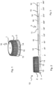
- the Figure 2 is side view of the closure Figure 1 to recognize and Figure 3 shows a 360° development of the tamper-evident strip 3, i.e., the ends of the tamper-evident strip shown on the right and left at 0° and 360°, respectively, abut and connect, so that the tamper-evident strip has an overall ring shape.
- the separation in this development view divides the separating strip 12 into two parts, although it is actually a single, continuous separating strip.
- the break lines 13, 14 are of different lengths, but are arranged in such a way that they overlap the separating web 11 or 12 of the other weakening line. It is advantageous if the centers of the separating webs 11, 12 are diametrically opposite each other, as in the present case at 0° and 180° in Figure 3 .
- the retaining bands 15, 16 formed in the overlapping area of the weakening line form a substantially tear-resistant connection between the interrupted areas 11, 12.
- the interrupted area 11 is connected to the lower edge of the screw cap, and the interrupted area 12 is connected to the part of the tamper-evident band 3 that remains in its original position and is located below the weakening line 14.
- the interrupted areas 12 and 11 are each connected to one another by remaining retaining bands 15, 16, which are created by the overlapping sections of the two weakening lines 13, 14, so that the screw cap 10 effectively remains connected to the lower section of the tamper-evident band and thus to the bottle neck via the retaining bands 15, 16, and is therefore captive.
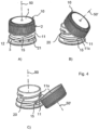
- FIG 4A shows a closure arranged on a bottle neck in a partially unscrewed state.
- the connection between screw cap 10 and tamper-evident strip 3 is severed along both weakening lines 13, 14.
- both weakening lines are interrupted and axially offset from one another at least in their overlapping area, a movable connection between screw cap 10 and tamper-evident strip 3 remains via the retaining bands 15, 16 created between the overlapping weakening lines. It is therefore understood that when the closure or screw cap 10 is released by a rotational movement in the opening direction with the cap jacket 2, the tamper-evident strip 3 also rotates around the closure axis 50 and is carried along in the circumferential direction by the retaining bands 15, 16.
- Figure 4A shows a state in which the screw cap 10 is already rotated by more than 90° relative to the initial position in Figure 4A tilted or folded over.
- the tilt angle is defined as the angle between the axis 50 of the container neck and the axis 50' of the cylindrical internal thread of the cap jacket 2, which coincide in the closed state of the closure on the bottle neck, while in the case of the open closure according to Figure 4C the axes 50, 50' have been tilted by approximately 150° relative to each other, starting from the closed position.
- interruption area 11 which, due to its connection with the cap jacket, simply represents a relatively stable, axial extension of the cap jacket 2.
- This divider11 will also be Form of a tab-like extension together with the stable closure jacket tilted and has in Figure 4C a horizontal position (perpendicular to the axis 50) is already slightly exceeded, whereby the retaining straps 15,16 are twisted accordingly.
- the lower edge 11a of the separating web 11 engages with the outside of the bottle neck 20, since the edge 11a is forced to a smaller radius than in the state according to Figure 4A .
- An upper flank of the pilferproof ring 21 inclined by approximately 30° or slightly less relative to the closure axis 50 supports the folding movement of the separating strip 11 when it slides onto the upper flank of the pilferproof ring 21
- the two retaining bands 15, 16 are twisted and the axial displacement of the upper separating web 11 of the tamper-evident band additionally leads to an effective reduction in the diameter of the tamper-evident band including the separating web 11, particularly in the area of the lower edge 11a.
- This lower edge 11a of the separating web 11 therefore comes into contact with the outside of the bottle neck 20 and engages frictionally, whereby the force occurring between the bottle neck 20 and the separating web 11 or the edge 11a is maximized when the separating web 11 is aligned approximately horizontally, i.e., perpendicular to the bottle neck axis 50.
- the retaining straps 15, 16 are then under tensile stress.
- the cap jacket is sufficiently far away from the bottle neck opening so that liquid can be poured out of the bottle as well as directly from the bottle can be drunk without the screw cap still attached to the bottle neck causing any interference.
- the screw cap 10 is tilted such that it is in a sufficiently stable position and the cap skirt 2 is at the greatest possible distance from the bottle neck opening.
- the pilfer-proof ring 21 on the bottle neck 20 can, among other things, be designed such that the screw cap 10 is pressed radially outward when folded over, thereby resulting in greater torsion of the retaining straps 15, 16 and consequently an increase in the tilt angle.
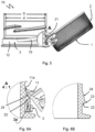
- Figure 5 shows a side view of a closure in a folded position.
- the area in which the separating web 11 engages with the bottle neck 20, more precisely with the pilferproof ring 21, is shown in a cross-sectional view and enlarged in Figure 6A shown.
- the profile of the pilferproof ring 21 is essentially triangular. In this case, the profile can also be described as nose-shaped.
- a lower flank 22 of the pilferproof ring extends almost perpendicular to the axis of the container neck 50. In accordance with the triangular profile, this lower flank 22 converges with an upper flank 24 in a region of maximum diameter.
- the region of maximum diameter is formed here as a rounded edge, which is also referred to here as a ridge 23 running between the lower flank 22 and the upper flank 24.
- the upper flank 24 is in the Figure 6A In the embodiment shown, the lower flank is positioned significantly flatter relative to the bottle neck 20 than the lower flank. In this case, the upper flank extends at an angle of approximately 30° to the axis of the container neck 50.
- the upper separating rib 11 When screwing on the screw cap 10, the upper separating rib 11 is now lifted over the ridge 23, in which the pilferproof ring 21 has its maximum diameter. During the subsequent tilting, the retaining bands 15 and 16 are twisted, and the lower edge 11A of the separating rib 11 slides onto the upper flank 24 of the pilferproof ring 21. In this case, the separating rib 11 is held further radially outward in the area swept over by the lower edge 11A of the separating rib 11 due to the larger diameter D of the upper flank 24 compared to the outer bottle neck diameter d than would otherwise be possible between the pilferproof ring 21 and the thread 25 and also at the thread base.
- the tilt angle is approximately 150°.
- FIG. 6B Another profile of a Pilferproofring 21 is in Figure 6B Compared to the Figure 6A In this case, the upper flank 24 is even flatter than the bottle neck 20 in the profile shown. The upper flank forms an angle of approximately 10° with the axis 50 of the container neck. Furthermore, the upper flank 24 extends over a larger axial section of the bottle neck 20.
- FIGS. 7, 8A and 8B Further examples are shown in which the pilferproof ring 21 has such a profile according to the invention or the bottle neck above the pilferproof ring has corresponding additional elements.
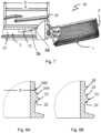
- Figure 7 The profile is designed similar to a trapezoid, with the lower flank 22 extending almost perpendicular to the axis of the container neck 50 and the upper flank 24 at an angle of approximately 45° to the axis of the container neck 50.
- the area of maximum diameter 23 extends axially upwards to such an extent that the separating web 11 remains largely below the upper flank 24 and is thus pressed radially outwards, again increasing the tilt angle of the screw cap 10 compared to a contact with the smaller (outer) diameter d of the bottle neck 20.
- FIG 8A A profile of a pilferproof ring 21 is shown, which in the lower part corresponds to the profile from the Figures 5 and 6A
- the upper flank 24 in the Figure 8A The embodiment shown merges into a short, cylindrical upper end section 24B, which defines a diameter D that is larger than the smaller diameter d of the bottle neck, against which the separating web 11 or its lower edge rests when the screw cap 10 is folded over. This ensures, in particular, that the screw cap 10 subsequently has a larger tilt angle in a sufficiently stable end position.
- FIG. 8B Another alternative is in Figure 8B shown.
- the bottle neck here has an annular projection 26 which is arranged all the way around the bottle neck above the upper flank 24 of the pilferproof ring 21.
- the axial position of the projection 26 is coordinated with the closure or the screw cap with the separating web 11 in such a way that the latter or its lower edge 11a abuts against the projection 26 from below and the screw cap is thus held at the bottom in the immediate vicinity of the pilferproof ring.
- the bands 15 could pull the upper separating web and thus the entire screw cap slightly upwards until the edge of the separating web abuts the thread.
- Figure 9 shows a further screw cap according to the present invention, partially in section.
- the screw cap 10 has the guarantee band 3 at its lower edge and a sectioned detail A of the lower area of the screw cap, including part of an associated bottle neck 20, is shown as an enlarged detail in Figure 9A shown separately.
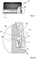
- Insert the screw cap 10 into the Figures 9, 9A and 10, 10A is the one in the Figures 5 and 6A shown screw cap with the exception of the fact that at least the separating web 11 has a radial thickening 11b at its lower edge, which in the present case also extends axially below and at the level of the thickening of the separating web 11 over the entire circumference of the tamper-evident strip 3.
- the tamper-evident strip has in this section below an imaginary line which lies between the upper and lower weakening lines and at a distance from these, a greater wall thickness than in the case of the Figures 5 and 6 ,
- the thickening 11b at the lower edge of the separating strip 11, has the purpose of keeping the opened screw cap wide open even when using a thread with a thread depth of more than 1.3 mm, as is the case, for example, in Figure 10 is shown.
- the upper weakening line 13 is due to the cutting plane of the Figure 9 not present in the area of the separating web 11.
- the separating web 11 is thus continuously connected to the cap jacket 2.
- the axial position of the upper weakening line would be approximately at the level of the maximum diameter of the pilferproof ring 21.
- the fastening part of the tamper-evident band is formed by a flexible band.
- This consists of a radially inner, upwardly folded part 3a and a radially outer flexible band section 3b, which remains stationary on the bottle neck even after the cap is opened.
- Figure 10A shows an enlarged detail of the closure in the opened position according to.
- the radial thickening 11b which here lies in the region of the transition between the upper flank of the pilfer-proof ring 21 and the bottle neck section above it, causes the imaginary radially inner part 11c of the separating web 11 (which corresponds to a separating web without a thickening), and in particular its lower edge, to be pressed radially outwards more strongly by the bottle neck 20 than if the thickening 11b were not present.
- the screw cap 10 remains in a stable, widely folded position, for example by 140°, despite the deeper thread profile.
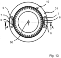
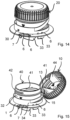
- FIGS 11 - 15 each show the same embodiment of a closure for cardboard packaging, in particular beverage cartons, and are therefore described in conjunction with each other.
- Figure 1 on average and in Figure 4 An external view of a closure base, designated overall by 40, consisting of a flange 31 with a pouring spout 32 attached thereto.
- the pouring spout has an upper opening and a lower opening, not visible here, which, when the closure is on a cardboard packaging, is initially closed by the surface of the cardboard material to prevent any contamination of the container contents.
- the flange 1 is glued or welded onto a cardboard 45, whereby the welding requires that the cardboard material 45 is provided with a suitable surface coating (e.g. polyethylene).
- a suitable surface coating e.g. polyethylene
- the lower part 40 of the closure has an external thread 42 onto which the internal thread 41 of a screw cap 10 can be screwed.
- the pouring spout 40 also has a further internal thread 31, into which a matching external thread of a cutting ring 35 engages, which also has axially projecting and, in the closed state, Figure 1 directly above the surface of the carton 45.
- a driver 34 engages with a matching counterpart 36 on the cutting ring 35 when the screw cap is turned in the opening direction.
- a fixing web 7 can be seen on the flange, which is connected to the lower end of the tamper-evident band 30 via two easily breakable bridges 6.
- the tamper-evident band has, as best seen in Figure 2 recognizes two cutting lines 18, 19, which are either caused by weakened material of the tamper-evident band 30 or, as in the present case, by continuous cuts interrupted only by further easily breakable bridges 36, which tear open when the screw cap is opened.
- the lower cut line 18 and the upper cut line 19 overlap each other, in the present case along a circumferential angle of approximately 120°, and each have a lower interrupted section 12 and an upper interrupted section 11.
- the easily breakable bridges 6 tear first and very quickly, indicating that the closure has been rotated at least once by a small angle in the opening direction, which may be sufficient for the cutting elements to pierce the cardboard material 45.
- the length of the retaining straps 15,16 ie the length of the overlapping areas of the cutting lines is according to Figure 4 adjusted so that the lower edge of the upper interruption section 11, when the screw cap 20 is open and folded over by approximately 150°, engages with the outside of the pouring spout 40 and the retaining straps 15, 16 are under tension, so that this position of the screw cap is held by the screw cap 40 by the tension of the retaining straps and the contact of the lower edge of the interruption section 11, even if the pouring spout is tilted in any direction together with the corresponding container.
Landscapes
- Engineering & Computer Science (AREA)
- Mechanical Engineering (AREA)
- Closures For Containers (AREA)
- Clamps And Clips (AREA)
- Ceramic Engineering (AREA)
Claims (15)
- Fermeture constituée d'un capuchon pouvant être vissé (10) avec une bande de garantie (3), qui comprend au moins une enveloppe de capuchon (2) cylindrique avec un taraudage et une bande de garantie (3) circonférentielle à l'extrémité ouverte inférieure de l'enveloppe de capuchon (2), qui est attachée au bord inférieur de l'enveloppe de capuchon (2) le long de lignes d'affaiblissement (13, 14) faciles à déchirer, après la déchirure, la bande de garantie (3) restant attachée au bord inférieur de l'enveloppe de capuchon, moyennant des bandes de retenue (15, 16), de façon inséparable le long des lignes d'affaiblissement, les bandes de retenue (15, 16) étant constituées par deux lignes d'affaiblissement (13, 14) interrompues au moins une fois dans le sens circonférentiel par une nervure de séparation (11, 12) et qui se chevauchent partiellement dans le sens circonférentiel et s'étendent, au moins dans la zone de chevauchement, à une distance axiale l'une de l'autre, et les nervures de séparation (11, 12) des deux lignes d'affaiblissement (13, 14) étant enjambées à une distance axiale par l'autre ligne d'affaiblissement (14, 13) respective,
caractérisée en ce quela bande de garantie (3) est configurée comme une bande flexible avec une partie radiale extérieure et une partie radiale intérieure repliée,la nervure de séparation (11) de la ligne d'affaiblissement supérieure (13) s'étendant sur un angle circonférentiel entre 10° et 75°,la nervure de séparation (12) de la ligne d'affaiblissement inférieure (14) s'étendant sur un angle circonférentiel entre 120° et 200°,la largeur des bandes de retenue, mesurée dans la direction axiale, étant supérieure à 1 mm et/ou la section stationnaire extérieure de la bande de garantie ayant, dans la zone circonférentielle des bandes de retenue et de la nervure de séparation supérieure, une largeur axiale de 2 à 3 mm. - Fermeture selon la revendication 1,
la fermeture étant configurée de façon telle qu'un axe du capuchon de fermeture prenne, après l'ouverture et repliage latéral, une position stable dans laquelle elle est pivotée par rapport à la position de départ et par rapport à l'axe du goulot d'au moins 120 degrés, de préférence de 140 degrés. - Fermeture selon l'une des revendications précédentes, caractérisée en ce que chaque ligne d'affaiblissement comprend précisément une nervure de séparation et que les points de milieux des nervures de séparation (11, 12) sont diamétralement opposés les uns aux autres.
- Fermeture selon l'une des revendications précédentes, caractérisée en ce que la nervure de séparation (11) de la ligne d'affaiblissement supérieure (13) s'étend sur un angle circonférentiel entre 20° et 60°.
- Fermeture selon l'une des revendications précédentes, caractérisée en ce que la nervure de séparation (12) de la ligne d'affaiblissement inférieure (14) s'étend sur un angle circonférentiel entre 170° et 190°.
- Fermeture selon l'une des revendications précédentes, caractérisée en ce que la largeur, mesurée en direction axiale, de la nervure de séparation supérieure (11) restant à l'enveloppe de capuchon (2) est d'au moins la moitié de la largeur de la bande de garantie (3) intacte.
- Fermeture selon l'une des revendications précédentes, caractérisée en ce que la largeur, mesurée en direction axiale, de la nervure de séparation supérieure (11) restant à l'enveloppe de capuchon (2) est d'au moins 1,5 mm, de préférence d'au moins 2 mm, notamment d'au moins 2,5 mm et de moins de 5 mm.
- Fermeture selon l'une des revendications précédentes, caractérisée en ce que l'épaisseur de la paroi de la bande de garantie (3) se situe entre 0,5 et 0,8 mm.
- Fermeture selon l'une des revendications précédentes, la largeur des bandes de retenue, mesurée en direction axiale, est supérieure à 2 mm, et est notamment supérieure à 2,3 mm.
- Fermeture selon l'une des revendications précédentes, la fermeture étant une fermeture pour emballage en carton.
- Combinaison d'un goulot de récipient avec filetage et d'une fermeture selon l'une des revendications précédentes.
- Combinaison selon la revendication précédente, le goulot comprenant, en plus d'une bague pilferproof (21), une saillie annulaire (26) qui est placée au goulot de façon circonférentielle au-dessus d'un côté (24) de la bague pilferproof (21).
- Combinaison selon la revendication précédente, la position axiale de la saillie étant ajustée sur le capuchon fileté à la nervure de séparation (11) de manière telle que celle-ci ou son bord inférieur (11a) bute par en-dessous contre la saillie (26) et que, de cette façon, le capuchon fileté (10) soit maintenu en-dessous à proximité immédiate de la bague pilferproof (21).
- Combinaison selon l'une des revendications 11 à 13, le diamètre extérieur du goulot (20) au-dessus d'une bague pilferproof (21), le diamètre intérieur de la bande de garantie (3) ainsi que la largeur et l'étendue circonférentielle de la nervure de séparation (11) étant ajustés les uns par rapport aux autres de manière telle que, après une rotation d'ouverture du capuchon fileté et le basculement qui s'en suit du capuchon fileté (10), tout en tordant les bandes de retenue (15, 16), le bord inférieur libre de la nervure de séparation (11a) s'emboîte avec le goulot (20) et est mû au-delà d'un point mort lors d'un dépassement d'un angle de pivotement de plus de 90°, si bien qu'ensuite, le côté extérieur de la nervure de séparation (11) entre en contact avec le côté extérieur du goulot (20) et que le capuchon fileté (10) est stabilisé dans cette position basculée de plus de 90°.
- Combinaison selon l'une des revendications 11 à 14, caractérisée en ce que, dans une zone au-dessus d'une bague pilferproof (20) dans laquelle la bande de garantie (3) est disposée, le diamètre extérieur du goulot (20) est plus petit, de tout au plus, de 2,5 mm, de préférence de 1,5 mm que le diamètre intérieur nominal de la bande de garantie (3).
Applications Claiming Priority (4)
| Application Number | Priority Date | Filing Date | Title |
|---|---|---|---|
| DE102018128886.7A DE102018128886A1 (de) | 2018-11-16 | 2018-11-16 | Unverlierbarer Verschluss |
| DE102019120725 | 2019-07-31 | ||
| EP19802116.4A EP3880574B1 (fr) | 2018-11-16 | 2019-11-06 | Dispositif de fermeture imperdable présentant un angle d'ouverture stabilisé |
| PCT/EP2019/080338 WO2020099200A1 (fr) | 2018-11-16 | 2019-11-06 | Dispositif de fermeture imperdable présentant un angle d'ouverture stabilisé |
Related Parent Applications (2)
| Application Number | Title | Priority Date | Filing Date |
|---|---|---|---|
| EP19802116.4A Division EP3880574B1 (fr) | 2018-11-16 | 2019-11-06 | Dispositif de fermeture imperdable présentant un angle d'ouverture stabilisé |
| EP19802116.4A Division-Into EP3880574B1 (fr) | 2018-11-16 | 2019-11-06 | Dispositif de fermeture imperdable présentant un angle d'ouverture stabilisé |
Publications (4)
| Publication Number | Publication Date |
|---|---|
| EP4303149A2 EP4303149A2 (fr) | 2024-01-10 |
| EP4303149A3 EP4303149A3 (fr) | 2024-03-13 |
| EP4303149B1 true EP4303149B1 (fr) | 2025-05-28 |
| EP4303149C0 EP4303149C0 (fr) | 2025-05-28 |
Family
ID=68542613
Family Applications (4)
| Application Number | Title | Priority Date | Filing Date |
|---|---|---|---|
| EP23211240.9A Active EP4303149B1 (fr) | 2018-11-16 | 2019-11-06 | Bouchon imperdable présentant un angle d'ouverture stabilisé |
| EP24166258.4A Active EP4403486B1 (fr) | 2018-11-16 | 2019-11-06 | Bouchon imperdable présentant un angle d'ouverture stabilisé |
| EP19802116.4A Active EP3880574B1 (fr) | 2018-11-16 | 2019-11-06 | Dispositif de fermeture imperdable présentant un angle d'ouverture stabilisé |
| EP21195586.9A Active EP3995410B1 (fr) | 2018-11-16 | 2019-11-06 | Combinaison d'un col de récipient et d'une fermeture imperdable à angle d'ouverture stabilisé |
Family Applications After (3)
| Application Number | Title | Priority Date | Filing Date |
|---|---|---|---|
| EP24166258.4A Active EP4403486B1 (fr) | 2018-11-16 | 2019-11-06 | Bouchon imperdable présentant un angle d'ouverture stabilisé |
| EP19802116.4A Active EP3880574B1 (fr) | 2018-11-16 | 2019-11-06 | Dispositif de fermeture imperdable présentant un angle d'ouverture stabilisé |
| EP21195586.9A Active EP3995410B1 (fr) | 2018-11-16 | 2019-11-06 | Combinaison d'un col de récipient et d'une fermeture imperdable à angle d'ouverture stabilisé |
Country Status (9)
| Country | Link |
|---|---|
| US (2) | US20220002021A1 (fr) |
| EP (4) | EP4303149B1 (fr) |
| CN (1) | CN113015683A (fr) |
| BR (1) | BR112021007456A2 (fr) |
| DE (1) | DE202019005974U1 (fr) |
| ES (3) | ES2974521T3 (fr) |
| HU (3) | HUE066464T2 (fr) |
| PL (3) | PL3880574T3 (fr) |
| WO (1) | WO2020099200A1 (fr) |
Families Citing this family (37)
| Publication number | Priority date | Publication date | Assignee | Title |
|---|---|---|---|---|
| US11312544B2 (en) * | 2020-03-30 | 2022-04-26 | ThisCap, Inc. | Cap for container |
| ES2974521T3 (es) | 2018-11-16 | 2024-06-27 | Bericap Holding Gmbh | Combinación de un cuello de recipiente y cierre imperdible con ángulo de apertura estabilizado |
| WO2020157695A1 (fr) | 2019-01-30 | 2020-08-06 | Sacmi Cooperativa Meccanici Imola Societa' Cooperativa | Capuchon permettant de fermer un récipient, combinaison d'un capuchon et d'un col |
| WO2020182854A1 (fr) | 2019-03-11 | 2020-09-17 | Alpla Werke Alwin Lehner Gmbh & Co. Kg | Fermeture de contenant et contenant |
| ES2799100A1 (es) | 2019-06-10 | 2020-12-14 | Nypro Inc | Tapón y caño amarrados |
| US11697534B2 (en) | 2019-07-22 | 2023-07-11 | Sacmi Cooperativa Meccanici Imola Societa' Cooperativa | Cap for a container, combination of a cap and a neck of the container and its production method |
| US12214935B2 (en) | 2019-07-22 | 2025-02-04 | Sacmi Cooperativa Meccanici Imola Societa'cooperativa | Cap for closing a container, a combination of a cap and a neck |
| WO2021046384A1 (fr) | 2019-09-06 | 2021-03-11 | Silgan White Cap LLC | Moyen de fermeture à charnières dotée d'une attache |
| US11505372B2 (en) | 2019-09-30 | 2022-11-22 | Berry Global, Inc. | Retainable closure |
| ES2964001T3 (es) * | 2019-11-29 | 2024-04-03 | Sig Combibloc Services Ag | Elemento de vertido resellable para envases compuestos de cartón/plástico con un anillo de anclaje para sujetar de manera segura una tapa roscada |
| DE102019132541C5 (de) * | 2019-11-29 | 2026-03-19 | Sig Services Ag | Wiederverschließbares Ausgießelement für Karton/Kunststoff-Verbundpackungen mit einem Ankerring zur sicheren Anbindung eines Schraubdeckels |
| US12606351B2 (en) * | 2019-12-12 | 2026-04-21 | Plastipak Packaging, Inc. | Tethered closure and container assembly |
| US12122561B2 (en) * | 2020-01-16 | 2024-10-22 | Closure Systems International Inc. | Package with tethered closure |
| US11718450B2 (en) * | 2020-01-24 | 2023-08-08 | Betapack, S.A.U. | Capping device intended to be fixed on the neck of a container and an assembly comprising a container and a capping device |
| DK3854716T3 (da) | 2020-01-27 | 2025-09-08 | Elopak Asa | Lukkeanordning til en papir- eller papbaseret emballage |
| DE102021117931A1 (de) | 2020-07-10 | 2022-01-13 | Rosti Gp Germany Gmbh | Mehrteiliger verschluss |
| US20230356901A1 (en) * | 2020-09-23 | 2023-11-09 | Sacmi Cooperativa Meccanici Imola Societa’ Cooperativa | Cap for container |
| MX2023003906A (es) * | 2020-10-05 | 2023-04-24 | Tetra Laval Holdings & Finance | Ensamble de cierre para un envase y envase que tiene un ensamble de cierre. |
| EP4277858B1 (fr) * | 2021-01-12 | 2026-02-25 | Sacmi Cooperativa Meccanici Imola Societa' Cooperativa | Capuchon pour récipient |
| US12583649B2 (en) * | 2021-05-24 | 2026-03-24 | Silgan White Cap LLC | Modified sidewall of tethered closure |
| EP4098574A1 (fr) * | 2021-06-03 | 2022-12-07 | SIG Combibloc Services AG | Fermeture d'un récipient à première ouverture à contrôle |
| IT202100017879A1 (it) * | 2021-07-07 | 2023-01-07 | Affaba & Ferrari S R L | Tappo compatto ad apertura rapida e assieme tappo e imboccatura di contenitore |
| WO2023285491A1 (fr) * | 2021-07-12 | 2023-01-19 | Rosti Group AB | Fermeture en plusieurs parties |
| US12065295B2 (en) * | 2021-08-19 | 2024-08-20 | Closure Systems International Inc. | One-piece closure |
| TWI807437B (zh) * | 2021-09-30 | 2023-07-01 | 宏全國際股份有限公司 | 切割連結蓋 |
| DE102021125520A1 (de) * | 2021-10-01 | 2023-04-06 | Bericap Holding Gmbh | Verschlussvorrichtung mit Stützring |
| EP4429966A4 (fr) * | 2021-11-08 | 2026-01-14 | Silgan White Cap LLC | Saillie sur le col d'un récipient |
| WO2023081880A1 (fr) * | 2021-11-08 | 2023-05-11 | Silgan White Cap LLC | Saillie sur le col d'un récipient |
| SE546886C2 (en) * | 2022-09-05 | 2025-03-04 | Modulpac Ab | Bottle closure and bottle provided with such closure |
| EP4361063A1 (fr) * | 2022-10-28 | 2024-05-01 | BERICAP Holding GmbH | Fermeture munie d'un maillon et d'une paroi de guidage pour un récipient |
| SE547849C2 (en) * | 2022-12-20 | 2025-12-09 | Emballator Vaexjoe Ab | A cap with a threaded portion for securing said cap to a bottle, the bottle and a method for manufacturing such a cap |
| PL73289Y1 (pl) * | 2023-02-28 | 2024-01-15 | Nowak Andrzej P H U P Nowex | Nakrętka z pierścieniem gwarancyjnym |
| PL73288Y1 (pl) * | 2023-02-28 | 2024-01-15 | Nowak Andrzej P H U P Nowex | Nakrętka z pierścieniem gwarancyjnym |
| PL245814B1 (pl) * | 2023-02-28 | 2024-10-14 | Nowak Andrzej P H U P Nowex | Nakrętka z pierścieniem gwarancyjnym |
| USD1056709S1 (en) | 2023-03-01 | 2025-01-07 | H. J. Heinz Company Brands Llc | Closure for a container |
| US12534276B2 (en) | 2024-03-12 | 2026-01-27 | Closure Systems International Inc. | Closure assembly and package with closure assembly |
| EP4667380A1 (fr) * | 2024-06-17 | 2025-12-24 | SIG Services AG | Element verseur pour emballages composites carton/plastique |
Family Cites Families (22)
| Publication number | Priority date | Publication date | Assignee | Title |
|---|---|---|---|---|
| US5360126A (en) * | 1992-12-21 | 1994-11-01 | Zapata Industries, Inc. | Tamper-evident plastic closure with 2-tier bridge arrangement |
| US5960992A (en) * | 1995-10-03 | 1999-10-05 | International Paper Company | Aseptic brick package spout |
| IT1290079B1 (it) | 1997-03-14 | 1998-10-19 | Tetra Laval Holdings & Finance | Dispositivo di apertura richiudibile per confezioni per prodotti alimentari versabili |
| FR2785264B1 (fr) * | 1998-10-29 | 2001-01-05 | Crown Cork & Seal Tech Corp | Dispositif de bouchage |
| US7261226B2 (en) | 2001-12-12 | 2007-08-28 | Portola Packaging, Inc. | Closure having rotatable spout and axially movable stem |
| EP1533240B1 (fr) * | 2003-11-18 | 2007-01-17 | Tetra Laval Holdings & Finance SA | Dispositif d'ouverture refermable pour conditionnements en feuille scellé de produits alimentaires versables |
| CN1830730A (zh) * | 2005-01-01 | 2006-09-13 | 郭永军 | 铰接式防盗瓶盖 |
| DE102006016113B3 (de) * | 2006-04-04 | 2007-08-23 | Sig Technology Ag | Wiederverschließbares Ausgießelement für Karton/Kunststoff-Verbundpackungen |
| US20110297682A1 (en) * | 2007-06-22 | 2011-12-08 | Si Joong Kwon | Container with anti-loss and anti-idle-rotation cap |
| JP2011500461A (ja) * | 2007-10-10 | 2011-01-06 | ベスト イージー キャップ カンパニー リミテッド | 栓紛失及び空回転防止容器 |
| DE102007057863A1 (de) * | 2007-11-29 | 2009-06-04 | Sig Technology Ag | Selbstöffnendes und wiederverschließbares Ausgießelement aus Kunststoff zur Applikation auf einer Packung für Flüssigkeiten |
| CN102652098B (zh) * | 2010-01-25 | 2014-10-29 | 权始重 | 防止瓶盖丢失或空转的容器 |
| JP2013518002A (ja) * | 2010-01-28 | 2013-05-20 | グリーンキャップ カンパニー リミテッド | 包装容器栓 |
| KR20100029797A (ko) * | 2010-02-19 | 2010-03-17 | 양두영 | 안전용기 캡 |
| CN102700822A (zh) * | 2012-05-15 | 2012-10-03 | 李红彪 | 瓶盖 |
| JP5948181B2 (ja) * | 2012-08-03 | 2016-07-06 | 日本クロージャー株式会社 | 合成樹脂製容器蓋 |
| CH708556A2 (de) * | 2013-09-05 | 2015-03-13 | Deltona Innovations Ag | Selbstöffnender Kunststoffverschluss. |
| US9776779B2 (en) | 2014-03-10 | 2017-10-03 | Phillip John Campbell | Closure with spring loaded tether docking |
| TWI589498B (zh) * | 2015-04-02 | 2017-07-01 | 邁可約瑟夫 麥奎爾 | 容器用之蓋子 |
| KR101744846B1 (ko) | 2016-11-14 | 2017-06-08 | 양복주 | 다목적 친환경캡 |
| WO2019207148A1 (fr) | 2018-04-26 | 2019-10-31 | Obrist Closures Switzerland Gmbh | Moyen de fermeture |
| ES2974521T3 (es) | 2018-11-16 | 2024-06-27 | Bericap Holding Gmbh | Combinación de un cuello de recipiente y cierre imperdible con ángulo de apertura estabilizado |
-
2019
- 2019-11-06 ES ES21195586T patent/ES2974521T3/es active Active
- 2019-11-06 EP EP23211240.9A patent/EP4303149B1/fr active Active
- 2019-11-06 CN CN201980075323.8A patent/CN113015683A/zh active Pending
- 2019-11-06 HU HUE21195586A patent/HUE066464T2/hu unknown
- 2019-11-06 ES ES19802116T patent/ES2992939T3/es active Active
- 2019-11-06 PL PL19802116.4T patent/PL3880574T3/pl unknown
- 2019-11-06 EP EP24166258.4A patent/EP4403486B1/fr active Active
- 2019-11-06 ES ES24166258T patent/ES3036201T3/es active Active
- 2019-11-06 PL PL24166258.4T patent/PL4403486T3/pl unknown
- 2019-11-06 PL PL21195586.9T patent/PL3995410T3/pl unknown
- 2019-11-06 BR BR112021007456-2A patent/BR112021007456A2/pt not_active IP Right Cessation
- 2019-11-06 EP EP19802116.4A patent/EP3880574B1/fr active Active
- 2019-11-06 HU HUE19802116A patent/HUE068432T2/hu unknown
- 2019-11-06 EP EP21195586.9A patent/EP3995410B1/fr active Active
- 2019-11-06 HU HUE24166258A patent/HUE071695T2/hu unknown
- 2019-11-06 US US17/280,787 patent/US20220002021A1/en not_active Abandoned
- 2019-11-06 WO PCT/EP2019/080338 patent/WO2020099200A1/fr not_active Ceased
- 2019-11-06 DE DE202019005974.1U patent/DE202019005974U1/de active Active
-
2022
- 2022-11-25 US US17/994,210 patent/US20230090849A1/en active Pending
Also Published As
| Publication number | Publication date |
|---|---|
| ES2974521T3 (es) | 2024-06-27 |
| EP3995410C0 (fr) | 2024-02-14 |
| EP4403486C0 (fr) | 2025-05-14 |
| EP3880574C0 (fr) | 2024-07-10 |
| PL4403486T3 (pl) | 2025-07-21 |
| BR112021007456A2 (pt) | 2021-07-20 |
| US20230090849A1 (en) | 2023-03-23 |
| EP4303149A2 (fr) | 2024-01-10 |
| EP3995410B1 (fr) | 2024-02-14 |
| EP3880574A1 (fr) | 2021-09-22 |
| ES2992939T3 (en) | 2024-12-20 |
| ES3036201T3 (en) | 2025-09-16 |
| CN113015683A (zh) | 2021-06-22 |
| HUE071695T2 (hu) | 2025-09-28 |
| EP3880574B1 (fr) | 2024-07-10 |
| PL3995410T3 (pl) | 2024-06-24 |
| WO2020099200A1 (fr) | 2020-05-22 |
| EP4403486B1 (fr) | 2025-05-14 |
| EP3995410A1 (fr) | 2022-05-11 |
| PL3880574T3 (pl) | 2024-10-28 |
| US20220002021A1 (en) | 2022-01-06 |
| EP4303149C0 (fr) | 2025-05-28 |
| DE202019005974U1 (de) | 2023-09-28 |
| EP4403486A1 (fr) | 2024-07-24 |
| HUE066464T2 (hu) | 2024-08-28 |
| EP4303149A3 (fr) | 2024-03-13 |
| HUE068432T2 (hu) | 2025-01-28 |
Similar Documents
| Publication | Publication Date | Title |
|---|---|---|
| EP4303149B1 (fr) | Bouchon imperdable présentant un angle d'ouverture stabilisé | |
| WO2021018772A1 (fr) | Bouchon captif ayant un angle d'ouverture stabilisé | |
| DE102018128886A1 (de) | Unverlierbarer Verschluss | |
| EP4065483B1 (fr) | Élément verseur refermable pour emballage composite carton/plastique doté d'une bague d'ancrage pour fixer solidement un bouchon à vis | |
| DE202019106993U1 (de) | Wiederverschließbares Ausgießelement für Karton/Kunststoff-Verbundpackungen mit einem Ankerring zur sicheren Anbindung eines Schraubdeckels | |
| WO2020099516A1 (fr) | Dispositif de fermeture relié | |
| DE102019132541B3 (de) | Wiederverschließbares Ausgießelement für Karton/Kunststoff-Verbundpackungen mit einem Ankerring zur sicheren Anbindung eines Schraubdeckels | |
| EP2566768B1 (fr) | Emballage avec fermeture filetée | |
| EP0916587A1 (fr) | Fermeture inviolable | |
| DE102020107184A1 (de) | Unverlierbarer Schraubverschluss | |
| DE19617350A1 (de) | Kappenarretierung | |
| WO2021018740A1 (fr) | Système de fermeture à vis imperdable | |
| EP3774568A1 (fr) | Bouchon à vis davantage inviolable | |
| EP2601112A1 (fr) | Fermeture à vis dotée d'une bande flexible | |
| DE102004038144B4 (de) | Verschlussvorrichtung für Behälter | |
| EP4251529B1 (fr) | Fermeture de récipient | |
| EP0387302B1 (fr) | Fermeture inviolable | |
| EP1529005B1 (fr) | Dispositif de fermeture/deversement combine comprenant une securite d'authenticite | |
| DE102010025158A1 (de) | Ausgießvorrichtung mit automatischem Öffnungsmerkmal | |
| DE2439414A1 (de) | Kunststoffverschluss fuer flaschen und behaelter | |
| DE102020106661A1 (de) | Wiederverschließbares Ausgießelement für Karton/Kunststoff-Verbundpackungen mit einem Ankerring zur sicheren Anbindung eines Schraubdeckels | |
| EP4419436B1 (fr) | Bague d'ancrage suspendue | |
| EP0891929B1 (fr) | Capuchon à vis avec bande de garantie | |
| DE102023129954A1 (de) | Hängender Ankerring | |
| DE4134338A1 (de) | Originalitaetsverschluss |
Legal Events
| Date | Code | Title | Description |
|---|---|---|---|
| PUAI | Public reference made under article 153(3) epc to a published international application that has entered the european phase |
Free format text: ORIGINAL CODE: 0009012 |
|
| STAA | Information on the status of an ep patent application or granted ep patent |
Free format text: STATUS: THE APPLICATION HAS BEEN PUBLISHED |
|
| AC | Divisional application: reference to earlier application |
Ref document number: 3880574 Country of ref document: EP Kind code of ref document: P |
|
| AK | Designated contracting states |
Kind code of ref document: A2 Designated state(s): AL AT BE BG CH CY CZ DE DK EE ES FI FR GB GR HR HU IE IS IT LI LT LU LV MC MK MT NL NO PL PT RO RS SE SI SK SM TR |
|
| REG | Reference to a national code |
Ref country code: DE Ipc: B65D0041340000 Ref legal event code: R079 Ref document number: 502019013396 Country of ref document: DE Free format text: PREVIOUS MAIN CLASS: B65D0055160000 |
|
| PUAL | Search report despatched |
Free format text: ORIGINAL CODE: 0009013 |
|
| AK | Designated contracting states |
Kind code of ref document: A3 Designated state(s): AL AT BE BG CH CY CZ DE DK EE ES FI FR GB GR HR HU IE IS IT LI LT LU LV MC MK MT NL NO PL PT RO RS SE SI SK SM TR |
|
| RIC1 | Information provided on ipc code assigned before grant |
Ipc: B65D 5/74 20060101ALI20240206BHEP Ipc: B65D 55/16 20060101ALI20240206BHEP Ipc: B65D 41/34 20060101AFI20240206BHEP |
|
| STAA | Information on the status of an ep patent application or granted ep patent |
Free format text: STATUS: REQUEST FOR EXAMINATION WAS MADE |
|
| 17P | Request for examination filed |
Effective date: 20240315 |
|
| RBV | Designated contracting states (corrected) |
Designated state(s): AL AT BE BG CH CY CZ DE DK EE ES FI FR GB GR HR HU IE IS IT LI LT LU LV MC MK MT NL NO PL PT RO RS SE SI SK SM TR |
|
| STAA | Information on the status of an ep patent application or granted ep patent |
Free format text: STATUS: EXAMINATION IS IN PROGRESS |
|
| 17Q | First examination report despatched |
Effective date: 20240604 |
|
| GRAP | Despatch of communication of intention to grant a patent |
Free format text: ORIGINAL CODE: EPIDOSNIGR1 |
|
| STAA | Information on the status of an ep patent application or granted ep patent |
Free format text: STATUS: GRANT OF PATENT IS INTENDED |
|
| INTG | Intention to grant announced |
Effective date: 20241129 |
|
| GRAJ | Information related to disapproval of communication of intention to grant by the applicant or resumption of examination proceedings by the epo deleted |
Free format text: ORIGINAL CODE: EPIDOSDIGR1 |
|
| STAA | Information on the status of an ep patent application or granted ep patent |
Free format text: STATUS: EXAMINATION IS IN PROGRESS |
|
| INTC | Intention to grant announced (deleted) | ||
| GRAP | Despatch of communication of intention to grant a patent |
Free format text: ORIGINAL CODE: EPIDOSNIGR1 |
|
| STAA | Information on the status of an ep patent application or granted ep patent |
Free format text: STATUS: GRANT OF PATENT IS INTENDED |
|
| INTG | Intention to grant announced |
Effective date: 20250217 |
|
| GRAS | Grant fee paid |
Free format text: ORIGINAL CODE: EPIDOSNIGR3 |
|
| GRAA | (expected) grant |
Free format text: ORIGINAL CODE: 0009210 |
|
| STAA | Information on the status of an ep patent application or granted ep patent |
Free format text: STATUS: THE PATENT HAS BEEN GRANTED |
|
| AC | Divisional application: reference to earlier application |
Ref document number: 3880574 Country of ref document: EP Kind code of ref document: P |
|
| AK | Designated contracting states |
Kind code of ref document: B1 Designated state(s): AL AT BE BG CH CY CZ DE DK EE ES FI FR GB GR HR HU IE IS IT LI LT LU LV MC MK MT NL NO PL PT RO RS SE SI SK SM TR |
|
| REG | Reference to a national code |
Ref country code: GB Ref legal event code: FG4D Free format text: NOT ENGLISH |
|
| REG | Reference to a national code |
Ref country code: CH Ref legal event code: EP |
|
| REG | Reference to a national code |
Ref country code: IE Ref legal event code: FG4D Free format text: LANGUAGE OF EP DOCUMENT: GERMAN Ref country code: DE Ref legal event code: R096 Ref document number: 502019013396 Country of ref document: DE |
|
| U01 | Request for unitary effect filed |
Effective date: 20250528 |
|
| U07 | Unitary effect registered |
Designated state(s): AT BE BG DE DK EE FI FR IT LT LU LV MT NL PT RO SE SI Effective date: 20250605 |
|
| PG25 | Lapsed in a contracting state [announced via postgrant information from national office to epo] |
Ref country code: ES Free format text: LAPSE BECAUSE OF FAILURE TO SUBMIT A TRANSLATION OF THE DESCRIPTION OR TO PAY THE FEE WITHIN THE PRESCRIBED TIME-LIMIT Effective date: 20250528 |
|
| PG25 | Lapsed in a contracting state [announced via postgrant information from national office to epo] |
Ref country code: GR Free format text: LAPSE BECAUSE OF FAILURE TO SUBMIT A TRANSLATION OF THE DESCRIPTION OR TO PAY THE FEE WITHIN THE PRESCRIBED TIME-LIMIT Effective date: 20250829 Ref country code: NO Free format text: LAPSE BECAUSE OF FAILURE TO SUBMIT A TRANSLATION OF THE DESCRIPTION OR TO PAY THE FEE WITHIN THE PRESCRIBED TIME-LIMIT Effective date: 20250828 |
|
| PG25 | Lapsed in a contracting state [announced via postgrant information from national office to epo] |
Ref country code: PL Free format text: LAPSE BECAUSE OF FAILURE TO SUBMIT A TRANSLATION OF THE DESCRIPTION OR TO PAY THE FEE WITHIN THE PRESCRIBED TIME-LIMIT Effective date: 20250528 |
|
| PG25 | Lapsed in a contracting state [announced via postgrant information from national office to epo] |
Ref country code: HR Free format text: LAPSE BECAUSE OF FAILURE TO SUBMIT A TRANSLATION OF THE DESCRIPTION OR TO PAY THE FEE WITHIN THE PRESCRIBED TIME-LIMIT Effective date: 20250528 |
|
| PG25 | Lapsed in a contracting state [announced via postgrant information from national office to epo] |
Ref country code: RS Free format text: LAPSE BECAUSE OF FAILURE TO SUBMIT A TRANSLATION OF THE DESCRIPTION OR TO PAY THE FEE WITHIN THE PRESCRIBED TIME-LIMIT Effective date: 20250828 |
|
| PG25 | Lapsed in a contracting state [announced via postgrant information from national office to epo] |
Ref country code: IS Free format text: LAPSE BECAUSE OF FAILURE TO SUBMIT A TRANSLATION OF THE DESCRIPTION OR TO PAY THE FEE WITHIN THE PRESCRIBED TIME-LIMIT Effective date: 20250928 |
|
| U20 | Renewal fee for the european patent with unitary effect paid |
Year of fee payment: 7 Effective date: 20251121 |
|
| PG25 | Lapsed in a contracting state [announced via postgrant information from national office to epo] |
Ref country code: SM Free format text: LAPSE BECAUSE OF FAILURE TO SUBMIT A TRANSLATION OF THE DESCRIPTION OR TO PAY THE FEE WITHIN THE PRESCRIBED TIME-LIMIT Effective date: 20250528 |
|
| PG25 | Lapsed in a contracting state [announced via postgrant information from national office to epo] |
Ref country code: CZ Free format text: LAPSE BECAUSE OF FAILURE TO SUBMIT A TRANSLATION OF THE DESCRIPTION OR TO PAY THE FEE WITHIN THE PRESCRIBED TIME-LIMIT Effective date: 20250528 |
|
| PG25 | Lapsed in a contracting state [announced via postgrant information from national office to epo] |
Ref country code: SK Free format text: LAPSE BECAUSE OF FAILURE TO SUBMIT A TRANSLATION OF THE DESCRIPTION OR TO PAY THE FEE WITHIN THE PRESCRIBED TIME-LIMIT Effective date: 20250528 |
|
| PLBE | No opposition filed within time limit |
Free format text: ORIGINAL CODE: 0009261 |
|
| STAA | Information on the status of an ep patent application or granted ep patent |
Free format text: STATUS: NO OPPOSITION FILED WITHIN TIME LIMIT |
|
| REG | Reference to a national code |
Ref country code: CH Ref legal event code: L10 Free format text: ST27 STATUS EVENT CODE: U-0-0-L10-L00 (AS PROVIDED BY THE NATIONAL OFFICE) Effective date: 20260409 |