EP4303371A1 - Sanitärarmatur mit verriegelungselement - Google Patents
Sanitärarmatur mit verriegelungselement Download PDFInfo
- Publication number
- EP4303371A1 EP4303371A1 EP22182711.6A EP22182711A EP4303371A1 EP 4303371 A1 EP4303371 A1 EP 4303371A1 EP 22182711 A EP22182711 A EP 22182711A EP 4303371 A1 EP4303371 A1 EP 4303371A1
- Authority
- EP
- European Patent Office
- Prior art keywords
- connection
- sanitary fitting
- locking element
- locking
- fitting
- Prior art date
- Legal status (The legal status is an assumption and is not a legal conclusion. Google has not performed a legal analysis and makes no representation as to the accuracy of the status listed.)
- Granted
Links
Images


Classifications
-
- E—FIXED CONSTRUCTIONS
- E03—WATER SUPPLY; SEWERAGE
- E03C—DOMESTIC PLUMBING INSTALLATIONS FOR FRESH WATER OR WASTE WATER; SINKS
- E03C1/00—Domestic plumbing installations for fresh water or waste water; Sinks
- E03C1/02—Plumbing installations for fresh water
- E03C1/04—Water-basin installations specially adapted to wash-basins or baths
- E03C1/042—Arrangements on taps for wash-basins or baths for connecting to the wall
-
- E—FIXED CONSTRUCTIONS
- E03—WATER SUPPLY; SEWERAGE
- E03C—DOMESTIC PLUMBING INSTALLATIONS FOR FRESH WATER OR WASTE WATER; SINKS
- E03C1/00—Domestic plumbing installations for fresh water or waste water; Sinks
- E03C1/02—Plumbing installations for fresh water
- E03C1/021—Devices for positioning or connecting of water supply lines
Definitions
- the present invention relates to a sanitary fitting with a cold water connection, a hot water connection and at least one water outlet.
- the cold water connection, the hot water connection and the at least one water outlet can be formed in a fitting body in which lines are also formed which connect the cold water connection and the hot water connection with the at least one water outlet.
- At least one receptacle can be formed in the fitting body.
- a mixing cartridge can be arranged in the receptacle to adjust the mixing ratio of hot and cold water and, if necessary, to adjust the flow.
- Further receptacles can also be formed, in which, for example, a switching device from a first water outlet to a second water outlet is arranged.
- Such a sanitary fitting can be connected to a building-side pipe using a connection device.
- the cold water connection is connected to a building-side cold water pipe by means of a first connection device and the hot water connection is connected to a building-side hot water pipe by means of a second connection device.
- connection device each has a so-called S-connection, the structural design of which can offer helpful compensation for dimensional deviations between the connections of the building's water pipes and the water connections of the fitting.
- Such an S-connection has a first end with which the S-connection can be connected to the building-side water pipe.
- the S connection has a second end to which the sanitary fitting is connected, if necessary using other components.
- the S-port extends from the first end in an axial direction, with the second end offset transversely of the first end.
- connection arrangement comprises a clamping element, which can be displaced against a connection element by means of an expansion element. In this way, a non-positive connection is provided between the sanitary fitting and the connection device.
- the elements of the connection arrangement are provided as separate components, so that the connection arrangement must be handled manually and separately for each line.
- the object of the present invention is therefore to eliminate the disadvantages described with reference to the prior art and in particular to propose a sanitary fitting that can be mounted easily and in particular at a predetermined distance from a wall.
- a sanitary fitting with the features mentioned at the outset, wherein the cold water connection and the hot water connection can each be connected to a building-side line by means of a connection device and in which at least one locking element on the sanitary fitting is movable, for example linearly displaceable, between an unlocking position and a locking position , is rotatably or pivotally mounted, wherein the sanitary fitting can be placed on the connection devices in the unlocking position and is secured against removal from the connection devices in the locking position.
- the basic idea of the invention is that a locking element is captively mounted on the sanitary fitting in such a way that it can be moved back and forth between two positions.
- the sanitary fitting and in particular the locking element are set up in such a way that the sanitary fitting can be placed on the connection devices already installed on the building and in an attached state the locking element can be moved into the locking position.
- the locking element is in particular designed so that it interacts with the connection devices in the locking position, so that the sanitary fitting is securely fastened to the connection devices and therefore cannot be easily removed from the connection devices. Since the at least one locking element is mounted on the sanitary fitting, it does not have to be handled separately during installation. This simplifies the assembly process.
- exactly one locking element is designed with which the sanitary fitting can be secured to the two connection devices at the same time.
- the locking element is spring-biased into the locking position by means of a spring. Assembly is also simplified using such a spring preload.
- the at least one locking element can be held in the unlocking position by means of at least one securing element, in which the sanitary fitting can be placed on the connection devices. After the fitting is placed on the connection devices, the securing element can be removed so that at least one Locking element can reach its locking position due to the spring preload.
- the sanitary fitting can be designed such that the locking element non-positively fixes the sanitary fitting in the locking position on the connection devices.
- the sanitary fitting and, if applicable, the connection devices are designed in such a way that the sanitary fitting is secured in the locking position in a form-fitting manner on the connection devices against removal by means of the at least one locking element.
- This can be achieved in particular by forming a type of undercut on the connection device, which is engaged behind by the at least one locking element in the locking position. In the locking position, the locking element is arranged relative to the undercut so that the sanitary fitting cannot be removed from the connection devices.
- Such an undercut design which is also referred to as a form-fitting design, can be formed, for example, by a circumferential groove on the connection device. In the locking position, the at least one locking element then engages in sections with an edge in the circumferential groove.
- the locking element has a recess for each connection device, which is shaped such that the connection device can reach through the recess in the unlocking position and a Edge of the recess comes into engagement with a positive locking design on the connection device when transferred into the locking position.
- the recess can have a first portion that is defined by a first diameter, the first diameter being so large that the locking element can be placed on the connection device.
- the recess has a second area which is characterized by a second diameter which is smaller than the first diameter, with an edge of this second area in the locking position interacting with the positive locking design preventing the sanitary fitting from being removed from the connection devices.
- the locking element is slidably mounted on the sanitary fitting.
- the locking element is mounted displaceably directly on the fitting body, so that forces from the locking element can be transferred directly to the fitting body.
- the locking element is displaceable in a direction that is predetermined by a direction from the hot water connection to the cold water connection.
- a particularly simple actuation of the locking element is possible thanks to a linearly displaceable bearing.
- spring preload can easily be implemented with a linearly displaceable bearing.
- the locking element is at least partially C-shaped in cross section, with the locking element preferably having recesses in a flat main section for receiving the connection devices and being displaceably mounted on the fitting body with free end sections.
- the locking element is both in the area of Cold water connection as well as in the area of the hot water connection on the fitting body is slidably mounted, the locking element being C-shaped in cross section precisely in these areas.
- the free ends of the locking element engage in linear grooves formed on the fitting body, so that the direction of displacement of the locking element is predetermined by the grooves on the fitting body.
- the recesses already described above, which accommodate the connection devices are formed in the flat and flat main section connecting the free ends.
- the sanitary fitting comprises a housing.
- the housing is in particular designed so that it largely covers the fitting body, with the housing coming into contact with an edge against a wall in the assembled position.
- Control elements for operating the sanitary fitting can be passed through the housing or arranged in the housing.
- the housing can in particular also have an opening through which the at least one water outlet of the fitting body is accessible.
- the locking element has an actuation projection, by means of which the locking element can be actuated from outside the housing.
- the actuating approach which is in particular formed in one piece with the locking element, extends in particular through an opening in the housing, whereby the opening can also be provided for other connecting parts or other functions. With the actuation approach, the locking element can be transferred from the locking position into the unlocking position, in particular against the spring force.
- the locking element in the locking position covers the water outlet formed on the fitting body. This ensures that, for example, a hose of a hand shower cannot be connected to the water outlet until the locking element has been moved into the locking position.
- a hose screwed into the water outlet secures the locking element against being transferred from the locking position to the unlocking position.
- the invention also relates to a sanitary fitting assembly kit which, in addition to a sanitary fitting according to the invention, comprises two connection devices, the connection devices each having a positive locking design which engages behind the locking element in the locking position in order to prevent the sanitary fitting from being removed from the connection devices.
- a form-fitting design (for example in the form of an undercut or in particular as a circumferential groove) is formed on the connection device, with which the locking element interacts in its locking position when attempting to remove the sanitary fitting from the connection devices in such a way that removal is prevented.
- the connection device includes in particular a conventional, water-conducting S-connection or an alternative water-conducting connection element.
- the S-connection and the water-carrying connection element have a first end with which the S-connection or the water-carrying connection element can be connected to a building-side pipe, with the S-connection or the water-carrying element extending away from the first end in an axial direction extends, wherein a second end of the S-connection or of the water-conducting connection element, onto which the sanitary fitting can be attached (if necessary using further components), is arranged offset transversely to the axial direction.
- the form-fitting design is formed in particular on an element of the connection device, which can be brought into different positions along an axial direction of the connection device.
- the form-fitting design is formed on a screw ring that is screwed onto the S-connection or the water-conducting connection element.
- the screw ring is screwed from the second end onto the S connection or the water-conducting connection element.
- a position of the form-fitting design can thus be adapted to the respective installation situation, so that the sanitary fitting and in particular a housing of the sanitary fitting rests flush against the wall after being put on, so that through the Screwed on screw ring specifies a distance between the sanitary fitting and the wall.
- the form-fitting design is formed in one piece on the water-conducting connection element.
- connection device can comprise a radially acting seal and an axially acting seal.
- the radially acting seal is in particular arranged so that it is arranged directly between the connection device and the corresponding connection of the sanitary fitting when the sanitary fitting is applied to the connection devices.
- the radially acting seal is arranged in particular in a radially circumferential groove on the connection device.
- connection device comprises an end cap that can be screwed onto a conventional S-connection.
- a circumferential groove is formed in a lateral surface of the end cap, in which the radially acting seal is arranged.
- an axially acting seal is arranged between the end cap and an axial end face of the S-connection at its second end.
- the water-conducting connection element has at its second end a groove running around its lateral surface, in which the radially acting seal is arranged.
- the installation of an end cap can therefore be dispensed with, and consequently the axial seal can also be dispensed with in this alternative embodiment.
- the sanitary fitting assembly kit comprises a securing element by means of which the locking element is held in the unlocking position before the sanitary fitting is placed on the connection devices.
- the securing element is preferably arranged in an opening in the housing of the sanitary fitting, which is assigned to the water outlet of the fitting body.
- the securing element cooperates in particular with an actuation approach formed on the locking element.
- Sanitary fitting 1 shown comprises a fitting body 7, a housing 8 and a locking element 6.
- the fitting body 7 forms a cold water connection 3, a hot water connection 4 and a water outlet 5.
- the fitting body 7 forms lines which lead from the cold water connection 3 or from the hot water connection 4 to a receptacle for a single-lever mixing cartridge and from there to the water outlet 5.
- the single-lever mixing cartridge protrudes beyond the housing 8 so that an actuating element can be operated by a user, with which both the mixed water temperature and the flow can be adjusted.
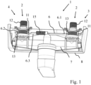
- the locking element 6 is slidably mounted on the fitting body 7. Like in particular from the Figure 3 As can be seen, the locking element 6 is C-shaped in the area of the hot water connection 4 and the cold water connection 3, with the free end sections 6.4 of the locking element 6 engaging in corresponding recesses on the fitting body 7. In the flat and flat main section 6.3 of the locking element 6, which is formed between the end sections 6.4, there are a first recess 6.1 and a second recess 6.2. In addition, the locking element 6 has an actuation approach 6.5 (see in particular Figures 4 and 5 ), which protrudes through an opening in the housing 8.
- connection devices 2 In the in Figures 1 to 5 In the configurations shown, the sanitary fitting 1 with its cold water connection 3 and its hot water connection 4 is each placed on a connection device 2.
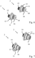
- connection devices 2 In Figure 6 are also the ones in the Figures 1 to 5 connection devices 2 shown.
- Figure 7 shows an alternative embodiment of two connection devices 2.
- connection device 2 shown comprises a conventional S-connection 12, which extends from a first end, with which the S-connection 12 can be attached to a building-side line, to a second end, the first end and the second end being arranged offset from one another .
- a screw ring 13 is screwed onto the second end, which has a positive locking design 11 in the form of a circumferential groove.
- the screw ring 13 also has a section which, when assembled, comes into contact with a wall (not shown).
- An end cap 18 is also screwed onto the second end of the S-connection 12, which carries a radial seal 16 on its lateral surface, for which purpose the lateral surface has a circumferential groove.
- the connection device 2 also includes an axial seal 17, which is arranged between the end cap 18 and an axial end face of the S-connection 12.
- connection devices 2 shown differ from the connection devices 2 of the Figure 6 in that instead of a conventional S-connection, a connection element 14 is used, at the second end of which a radial seal 16 is arranged.
- a connection element 14 is used, at the second end of which a radial seal 16 is arranged.
- the second end of the connecting element 14, which is offset from the first end has a circumferential groove on its lateral surface in which the radial seal 16 is arranged.
- the recesses 6.1 and 6.2 formed in the main section 6.3 of the locking element 6 have a first section, the diameter of which is chosen to be so large that the sanitary fittings in the Figures 1 and 4 shown unlocking position can be placed on the connection devices 2.
- the screw ring 13 with the form-fitting design 11 passes through the recess assigned to it. Due to the preload provided by a spring 15, the locking element can be in the Figures 2 and 5 reach the locking position shown, in which the edge of the respective recess 6.1 and 6.2 reaches the positive locking design 11. A positive connection is thus established between the locking element 6 and the screw ring 13, so that the sanitary fitting 1 cannot be removed from the connection devices 2.
- the locking element 6 is held in the unlocking position by a securing element 10.
- the securing element 10 is inserted into an opening in the housing 8, the securing element 10 fixing the actuating projection 6.5 of the locking element 6 so that the locking element 6 is held in the unlocking position against the spring preload.
- the sanitary fitting 1 can be placed on the connection devices 2 that are already connected to the building-side pipes.
- the securing element 10 can be removed so that the locking element 6 moves in the direction of the locking position. If the sanitary fitting 1 is aligned with the connection devices 2 so that the locking element 6 can engage with the edges of the recesses 6.1 and 6.2 in the positive locking designs 11, the locking element is in the locking position.
- the water outlet 5 on the fitting body 7 is only released when the locking element 6 is in the locking position. In this position, a hose 9 can be screwed into the water outlet 5.
Landscapes
- Health & Medical Sciences (AREA)
- Life Sciences & Earth Sciences (AREA)
- Engineering & Computer Science (AREA)
- Hydrology & Water Resources (AREA)
- Public Health (AREA)
- Water Supply & Treatment (AREA)
- Quick-Acting Or Multi-Walled Pipe Joints (AREA)
Abstract
Description
- Die vorliegende Erfindung betrifft eine Sanitärarmatur mit einem Kaltwasseranschluss, einem Heißwasseranschluss und mindestens einem Wasserauslass.
- Der Kaltwasseranschluss, der Heißwasseranschluss und der mindestens eine Wasserauslass können in einem Armaturenkörper ausgebildet sein, in dem auch Leitungen ausgebildet sind, die den Kaltwasseranschluss und den Heißwasseranschluss mit dem mindestens einem Wasserauslass verbinden. In dem Armaturenkörper kann mindestens eine Aufnahme ausgebildet sein. In der Aufnahme kann beispielsweise eine Mischkartusche zur Einstellung des Mischverhältnisses von Heiß- und Kaltwasser sowie gegebenenfalls zur Einstellung des Flusses angeordnet sein. Es können auch weitere Aufnahmen ausgebildet sein, in denen beispielsweise eine Umschaltvorrichtung von einem ersten Wasserauslass zu einem zweiten Wasserauslass angeordnet ist.
- Eine solche Sanitärarmatur kann mittels jeweils einer Anschlusseinrichtung an eine gebäudeseitige Leitungen angeschlossen werden. So wird der Kaltwasseranschluss mittels einer ersten Anschlusseinrichtung an eine gebäudeseitige Kaltwasserleitung und der Heißwasseranschluss mittels einer zweiten Anschlusseinrichtung an eine gebäudeseitige Heißwasserleitung angeschlossen.
- Es ist hierbei bekannt, dass die Anschlusseinrichtung jeweils einen sogenannten S-Anschluss aufweist, dessen konstruktive Gestaltung einen hilfreichen Ausgleich bei Maßabweichungen zwischen den Anschlüssen der gebäudeseitigen Wasserleitungen und den Wasseranschlüssen der Armatur bieten kann.
- Ein solcher S-Anschluss weist ein erstes Ende auf, mit welchem der S-Anschluss an die gebäudeseitige Wasserleitung anschließbar ist. Zudem weist der S-Anschluss ein zweites Ende auf, an welches die Sanitärarmatur gegebenenfalls unter Verwendung von weiteren Bauteilen angeschlossen wird. Der S-Anschluss erstreckt sich von dem ersten Ende in eine axiale Richtung, wobei das zweite Ende quer zu dem ersten Ende versetzt ist.
- Aus
DE 10 2019 103 607 A1 ist eine Sanitärarmatur bekannt, die mittels einer Anschlussanordnung an gebäudeseitige Leitungen angeschlossen werden kann. Es wird vorgeschlagen, dass die Anschlussanordnung ein Spannelement umfasst, welches mittels eines Spreizelements gegen ein Anschlusselement verschoben werden kann. Auf diese Weise wird eine kraftschlüssige Verbindung zwischen der Sanitärarmatur und der Anschlusseinrichtung bereitgestellt. Die Elemente der Anschlussanordnung sind als separate Bauteile zur Verfügung gestellt, so dass die Anschlussanordnung für jede Leitung manuell und separat gehandhabt werden muss. - Diese bereits bekannten Befestigungsmethoden für wandhängende Mischarmaturen sind teils kostenintensiv in ihrer Herstellung und/oder bedürfen eines gewissen bauseitigen Aufwandes bei der Montage der Armaturen. Zudem besteht bei Anschlussbefestigungen, die sich ausnahmslos das Wirkprinzip einer kraftschlüssigen Verbindung zunutze machen, die Gefahr, dass die Sicherheit gegen ein unbeabsichtigtes Lösen einer solchen Verbindung, sich bei der bauseitigen Montage nur schwer überprüfen lässt.
- Aufgabe der vorliegenden Erfindung ist es daher, die mit Bezug zum Stand der Technik geschilderten Nachteile zu beseitigen und insbesondere eine Sanitärarmatur vorzuschlagen, die einfach und insbesondere mit einem vorgegebenen Abstand zu einer Wand montierbar ist.
- Eine Lösung für diese Aufgabe ist mit der Sanitärarmatur mit den Merkmalen des unabhängigen Anspruchs angegeben. Weitere Lösungen und vorteilhafte Weiterbildungen sind in der vorstehenden und nachfolgenden Beschreibung sowie in den abhängigen Ansprüchen angegeben, wobei einzelne Merkmale der vorteilhaften Weiterbildungen in technisch sinnvoller Weise miteinander kombinierbar sind.
- Gelöst wird die Aufgabe insbesondere durch eine Sanitärarmatur mit den eingangs genannten Merkmalen, wobei der Kaltwasseranschluss und der Heißwasseranschluss jeweils mittels einer Anschlusseinrichtung an eine gebäudeseitige Leitung anschließbar sind und bei der an der Sanitärarmatur mindestens ein Verriegelungselement zwischen einer Entriegelungsstellung und einer Verriegelungsstellung beweglich, beispielsweise linear verschiebbar, drehbar oder schwenkbar gelagert ist, wobei die Sanitärarmatur in der Entriegelungsstellung auf die Anschlusseinrichtungen aufsetzbar ist und in der Verriegelungsstellung gegen ein Abnehmen von den Anschlusseinrichtungen gesichert ist.
- Mit anderen Worten: Die Erfindung sieht in ihrem Grundgedanken vor, dass an der Sanitärarmatur ein Verriegelungselement unverlierbar in einer solchen Art beweglich gelagert ist, dass es zwischen zwei Stellungen hin und her bewegbar ist. Die Sanitärarmatur und insbesondere das Verriegelungselement sind dabei so eingerichtet, dass die Sanitärarmatur auf die bereits gebäudeseitig installierten Anschlusseinrichtungen aufsetzbar ist und in einem aufgesetzten Zustand das Verriegelungselement in die Verriegelungsstellung überführbar ist. Das Verriegelungselement ist insbesondere so ausgebildet, dass es in der Verriegelungsstellung mit den Anschlusseinrichtungen wechselwirkt, so dass die Sanitärarmatur an den Anschlusseinrichtungen sicher festgelegt ist und somit nicht ohne weiteres von den Anschlusseinrichtungen abgenommen werden kann. Da das mindestens eine Verriegelungselement an der Sanitärarmatur gelagert ist, muss es nicht aufwendig bei der Installation separat gehandhabt werden. Somit ist der Montageprozess vereinfacht.
- Zur weiteren Vereinfachung der Montage ist in einer Ausführungsform vorgesehen, dass genau ein Verriegelungselement ausgebildet ist, mit welchem die Sanitärarmatur an den beiden Anschlusseinrichtungen gleichzeitig gesichert werden kann.
- Es kann zudem vorgesehen sein, dass das Verriegelungselement mittels einer Feder in die Verriegelungsstellung federvorgespannt ist. Auch mittels einer solchen Federvorspannung wird die Montage vereinfacht. So kann beispielsweise das mindestens eine Verriegelungselement mittels mindestens eines Sicherungselements in der Entriegelungsstellung gehalten werden, in welcher die Sanitärarmatur auf die Anschlusseinrichtungen aufgesetzt werden kann. Nachdem die Armatur auf die Anschlusseinrichtungen aufgesetzt ist, kann das Sicherungselement entfernt werden, so dass das mindestens eine Verriegelungselement aufgrund der Federvorspannung in seine Verriegelungsstellung gelangen kann.
- Prinzipiell kann die Sanitärarmatur so ausgebildet sein, dass das Verriegelungselement die Sanitärarmatur kraftschlüssig in der Verriegelungsstellung an den Anschlusseinrichtungen fixiert.
- Bevorzugt ist aber vorgesehen, dass die Sanitärarmatur und gegebenenfalls die Anschlusseinrichtungen so ausgebildet sind, dass die Sanitärarmatur mittels des mindestens einen Verriegelungselements in der Verriegelungsstellung formschlüssig an den Anschlusseinrichtungen gegen ein Abnehmen gesichert ist. Dies kann insbesondere dadurch erreicht werden, dass an der Anschlusseinrichtung eine Art Hinterschnitt ausgebildet ist, die von dem mindestens einem Verriegelungselement in der Verriegelungsstellung hintergriffen wird. In der Verriegelungsstellung ist das Verriegelungselement also so zu dem Hinterschnitt angeordnet, dass die Sanitärarmatur nicht von den Anschlusseinrichtungen abgenommen werden kann.
- Eine solche Hinterschnittgestaltung, welche auch als Formschlussgestaltung bezeichnet wird, kann beispielsweise durch eine umlaufende Nut an der Anschlusseinrichtung ausgebildet sein. In der Verriegelungsstellung greift dann das mindestens eine Verriegelungselement mit einer Kante abschnittsweise in die umlaufende Nut ein.
- Insbesondere wenn genau ein Verriegelungselement für alle Anschlusseinrichtungen vorgesehen ist, kann vorgesehen sein, dass das Verriegelungselement für jede Anschlusseinrichtung eine Aussparung aufweist, die so geformt ist, dass die Anschlusseinrichtung in der Entriegelungsstellung durch die Aussparung hindurchgreifen kann und ein Rand der Aussparung beim Überführen in die Verriegelungsstellung in Eingriff mit einer Formschlussgestaltung an der Anschlusseinrichtung gelangt. So kann die Aussparung beispielsweise einen ersten Teilbereich aufweisen, der durch einen ersten Durchmesser definiert ist, wobei der erste Durchmesser so groß ist, dass das Verriegelungselement auf die Anschlusseinrichtung aufgesetzt werden kann. Die Aussparung weist in diesem Fall einen zweiten Bereich auf, der durch einen zweiten Durchmesser charakterisiert ist, welcher kleiner ist als der erste Durchmesser, wobei ein Rand dieses zweiten Bereichs in der Verriegelungsstellung in Wechselwirkung mit der Formschlussgestaltung ein Abnehmen der Sanitärarmatur von den Anschlusseinrichtungen verhindert.
- In einer besonders bevorzugten Ausführungsform ist vorgesehen, dass das Verriegelungselement an der Sanitärarmatur verschiebbar gelagert ist. Insbesondere ist das Verriegelungselement unmittelbar an dem Armaturenkörper verschiebbar gelagert, so dass Kräfte von dem Verriegelungselement unmittelbar auf den Armaturenkörper übertragbar sind. Hierbei kann vorgesehen sein, dass das Verriegelungselement in einer Richtung verschiebbar ist, die durch eine Richtung von dem Heißwasseranschluss zu dem Kaltwasseranschluss vorgegeben ist. Durch eine linear verschiebbare Lagerung ist eine besonders einfache Betätigung des Verriegelungselements möglich. Zudem kann bei einer linear verschiebbaren Lagerung einfach eine Federvorspannung realisiert werden.
- Insbesondere in diesem Zusammenhang kann vorgesehen sein, dass das Verriegelungselement zumindest abschnittsweise im Querschnitt C-förmig ist, wobei bevorzugt das Verriegelungselement in einem flächigen Hauptabschnitt Aussparungen zur Aufnahme der Anschlusseinrichtungen aufweist und mit freien Endabschnitten verschiebbar an dem Armaturenkörper gelagert ist. Insbesondere ist das Verriegelungselement sowohl im Bereich des Kaltwasseranschlusses als auch im Bereich des Heißwasseranschlusses an dem Armaturenkörper verschiebbar gelagert, wobei das Verriegelungselement genau in diesen Bereichen im Querschnitt C-förmig ausgebildet ist. Die freien Enden des Verriegelungselements greifen in diesem Bereich in an dem Armaturenkörper ausgebildete lineare Nuten ein, so dass die Verschieberichtung des Verriegelungselements durch die Nuten am Armaturenkörper vorgegeben ist. In dem die freien Enden verbindenden flächigen und ebenen Hauptabschnitt sind insbesondere die bereits oben beschriebenen Aussparungen ausgebildet, welche die Anschlusseinrichtungen aufnehmen.
- In einer Ausführungsform kann zudem vorgesehen sein, dass die Sanitärarmatur ein Gehäuse umfasst. Das Gehäuse ist insbesondere so ausgebildet, dass es den Armaturenkörper zum Großteil abdeckt, wobei das Gehäuse in der montierten Stellung mit einem Rand an einer Wand zur Anlage kommt. Bedienelemente zur Betätigung der Sanitärarmatur können durch das Gehäuse hindurchgeführt sein oder in dem Gehäuse angeordnet sein. Das Gehäuse kann insbesondere auch eine Öffnung aufweisen, durch welche hindurch der mindestens eine Wasserauslass des Armaturenkörpers zugänglich ist.
- Es wird auch vorgeschlagen, dass das Verriegelungselement einen Betätigungsansatz aufweist, mittels welchem das Verriegelungselement von außerhalb des Gehäuses betätigbar ist. Der insbesondere einteilig mit dem Verriegelungselement ausgebildete Betätigungsansatz erstreckt sich insbesondere durch eine Öffnung im Gehäuse hindurch, wobei die Öffnung auch für andere Anschlussteile oder auch andere Funktionen vorgesehen sein kann. Mit dem Betätigungsansatz lässt sich das Verriegelungselement insbesondere entgegen der Federkraft von der Verriegelungsstellung in die Entriegelungsstellung überführen.
- Um zu verhindern, dass die Sanitärarmatur in Betrieb genommen werden kann, bevor das Verriegelungselement vorschriftsgemäß in seine Verriegelungsstellung gelangt ist, ist vorgesehen, dass das Verriegelungselement in der Verriegelungsstellung den an dem Armaturenkörper ausgebildeten Wasserauslass verdeckt. Somit ist sichergestellt, dass beispielsweise ein Schlauch einer Handbrause nicht mit dem Wasserauslass verbunden werden kann, bevor das Verriegelungselement nicht in die Verriegelungsstellung überführt wurde.
- Um zu verhindern, dass das Verriegelungselement nach einer Montage unbeabsichtigt aus der Verriegelungsstellung in die Entriegelungsstellung überführt wird, wird vorgeschlagen, dass ein in den Wasserauslass eingeschraubter Schlauch das Verriegelungselement gegen eine Überführung von der Verriegelungsstellung in die Entriegelungsstellung sichert.
- Die Erfindung betrifft auch einen Sanitärarmaturmontagebausatz, welcher neben einer erfindungsgemäßen Sanitärarmatur zwei Anschlusseinrichtungen umfasst, wobei die Anschlusseinrichtungen jeweils eine Formschlussgestaltung aufweisen, die das Verriegelungselement in der Verriegelungsstellung hintergreift, um ein Abnehmen der Sanitärarmatur von den Anschlusseinrichtungen zu verhindern. An der Anschlusseinrichtung ist also jeweils eine Formschlussgestaltung (beispielsweise in Form eines Hinterschnitts oder insbesondere als umlaufende Nut) ausgebildet, mit der das Verriegelungselement in seiner Verriegelungsstellung beim Versuch einer Abnahme der Sanitärarmatur von den Anschlusseinrichtungen so wechselwirkt, dass eine Abnahme verhindert ist.
- Die Anschlusseinrichtung umfasst insbesondere einen konventionellen, wasserführenden S-Anschluss oder ein alternatives wasserführendes Anschlusselement. Der S-Anschluss und das wasserführende Anschlusselement weisen ein erstes Ende auf, mit dem der S-Anschluss beziehungsweise das wasserführende Anschlusselement an eine gebäudeseitige Leitung anschließbar sind, wobei sich der S-Anschluss beziehungsweise das wasserführende Element in einer axialen Richtung von dem ersten Ende weg erstreckt, wobei ein zweites Ende des S-Anschlusses beziehungsweise des wasserführenden Anschlusselements, auf welches die Sanitärarmatur aufbringbar ist (gegebenenfalls unter Verwendung weiterer Bauteile), dabei quer zu der axialen Richtung versetzt angeordnet ist.
- Die Formschlussgestaltung ist insbesondere an einem Element der Anschlusseinrichtung ausgebildet, welches entlang einer axialen Richtung der Anschlusseinrichtung in unterschiedliche Positionen bringbar ist.
- In einer Ausführungsform wird hierzu vorgeschlagen, dass die Formschlussgestaltung an einem Schraubring ausgebildet ist, der auf den S-Anschluss beziehungsweise das wasserführende Anschlusselement aufgeschraubt ist. Insbesondere ist der Schraubring von dem zweiten Ende auf den S-Anschluss beziehungsweise das wasserführende Anschlusselement aufgeschraubt. Mittels des Schraubrings kann die Formschlussgestaltung der Anschlusseinrichtung bezüglich der die gebäudeseitigen Leitungen aufweisenden Wand so ausgerichtet werden, dass die Sanitärarmatur nach dem Aufsetzen bündig an der Wand aufliegt und das Verriegelungselement in die Verriegelungsstellung gelangen kann. Somit kann eine Lage der Formschlussgestaltung an die jeweilige Einbausituation angepasst werden, so dass die Sanitärarmatur und insbesondere ein Gehäuse der Sanitärarmatur nach dem Aufsetzen bündig an der Wand anliegt, so dass durch den aufgeschraubten Schraubring ein Abstand der Sanitärarmatur zu der Wand vorgegeben wird.
- In einer alternativen Ausführungsform kann vorgesehen sein, dass die Formschlussgestaltung einteilig an dem wasserführenden Anschlusselement ausgebildet ist.
- Die Anschlusseinrichtung kann eine radial wirkende Dichtung und eine axial wirkende Dichtung umfassen. Die radial wirkende Dichtung ist insbesondere so angeordnet, dass sie unmittelbar zwischen der Anschlusseinrichtung und dem entsprechenden Anschluss der Sanitärarmatur angeordnet ist, wenn die Sanitärarmatur auf die Anschlusseinrichtungen aufgebracht ist. Die radial wirkende Dichtung ist insbesondere in einer radial umlaufenden Nut an der Anschlusseinrichtung angeordnet.
- Hierbei kann vorgesehen sein, dass die Anschlusseinrichtung eine Endkappe umfasst, die auf einen herkömmlichen S-Anschluss aufschraubbar ist. In diesem Fall ist eine umlaufende Nut in einer Mantelfläche der Endkappe ausgebildet, in welcher die radial wirkende Dichtung angeordnet ist. Bei dieser Ausführungsform ist eine axial wirkende Dichtung zwischen der Endkappe und einer axialen Stirnseite des S-Anschlusses an seinem zweiten Ende angeordnet.
- In einer alternativen Ausführungsform wird vorgeschlagen, dass das wasserführende Anschlusselement an seinem zweiten Ende eine auf seiner Mantelfläche umlaufende Nut aufweist, in der die radial wirkende Dichtung angeordnet ist. Es kann somit auf die Montage einer Endkappe verzichtet werden, folglich kann auch die die axiale Dichtung in dieser alternativen Ausführungsform entfallen.
- Es wird ferner vorgeschlagen, dass der Sanitärarmaturmontagebausatz ein Sicherungselement umfasst, mittels welchem das Verriegelungselement vor dem Aufsetzen der Sanitärarmatur auf die Anschlusseinrichtungen in der Entriegelungsstellung gehalten ist. Bevorzugt ist das Sicherungselement in einer Öffnung in dem Gehäuse der Sanitärarmatur angeordnet, welches dem Wasserauslass des Armaturenkörpers zugeordnet ist. Das Sicherungselement wirkt dabei insbesondere mit einem an dem Verriegelungselement ausgebildeten Betätigungsansatz zusammen.
- Die Erfindung sowie das technische Umfeld werden im Folgenden anhand der Figuren beispielhaft erläutert. Die Figuren zeigen schematisch
- Figur 1:
- eine Sanitärarmatur in einem auf Anschlusseinrichtungen aufgesetzten Zustand, bei der sich ein Verriegelungselement in einer Entriegelungsstellung befindet,
- Figur 2:
- die Sanitärarmatur gemäß
Figur 1 , bei der sich das Verriegelungselement in einer Verriegelungsstellung befindet, - Figur 3:
- eine Schnittansicht durch die Sanitärarmatur der
Figur 2 im Bereich eines Heißwasseranschlusses, - Figur 4:
- eine Perspektivansicht der Sanitärarmatur in der in
Figur 1 dargestellten Entriegelungsstellung, - Figur 5:
- eine Perspektivansicht der Sanitärarmatur in der in
Figur 2 dargestellten Verriegelungsstellung, - Figur 6:
- eine erste Ausführungsform von zwei Anschlusseinrichtungen und
- Figur 7:
- eine zweite Ausführungsform von zwei Anschlusseinrichtungen.
- Die in den
Figuren 1 bis 5 dargestellte Sanitärarmatur 1 umfasst einen Armaturenkörper 7, ein Gehäuse 8 und ein Verriegelungselement 6. - Der Armaturenkörper 7 bildet einen Kaltwasseranschluss 3, einen Heißwasseranschluss 4 sowie einen Wasserauslass 5 aus. Zudem bildet der Armaturenkörper 7 Leitungen aus, die von dem Kaltwasseranschluss 3 beziehungsweise von dem Heißwasseranschluss 4 zu einer Aufnahme für eine Einhebelmischkartusche führen und von dort zum Wasserauslass 5.
- Die Einhebelmischkartusche steht über das Gehäuse 8 hervor, so dass ein Betätigungselement von einem Benutzer bedient werden kann, mit welchem sowohl die Mischwassertemperatur als auch der Durchfluss eingestellt werden kann.
- Das Verriegelungselement 6 ist verschiebbar an dem Armaturenkörper 7 gelagert. Wie insbesondere aus der
Figur 3 hervorgeht, ist das Verriegelungselement 6 hierzu im Bereich des Heißwasseranschlusses 4 und des Kaltwasseranschlusses 3 C-förmig ausgebildet, wobei die freien Endabschnitte 6.4 des Verriegelungselements 6 hierbei in entsprechende Ausnehmungen am Armaturenkörper 7 eingreifen. In dem ebenen und flachen Hauptabschnitt 6.3 des Verriegelungselements 6, welcher zwischen den Endabschnitten 6.4 ausgebildet ist, sind eine erste Aussparung 6.1 und eine zweite Aussparung 6.2 vorhanden. Zudem weist das Verriegelungselement 6 einen Betätigungsansatz 6.5 auf (siehe insbesondereFiguren 4 und 5 ), welcher durch eine Öffnung in dem Gehäuse 8 hervorsteht. - In den in
Figuren 1 bis 5 gezeigten Konfigurationen ist die Sanitärarmatur 1 mit ihrem Kaltwasseranschluss 3 und ihrem Heißwasseranschluss 4 jeweils auf eine Anschlusseinrichtung 2 aufgesetzt. InFigur 6 sind auch die in denFiguren 1 bis 5 dargestellten Anschlusseinrichtungen 2 gezeigt.Figur 7 zeigt eine alternative Ausführungsform von zwei Anschlusseinrichtungen 2. - Die in
Figur 6 dargestellte Anschlusseinrichtung 2 umfasst einen herkömmlichen S-Anschluss 12, welcher sich von einem ersten Ende, mit welchem der S-Anschluss 12 an eine gebäudeseitige Leitung anbringbar ist, zu einem zweiten Ende erstreckt, wobei das erste Ende und das zweite Ende versetzt zueinander angeordnet sind. Auf das zweite Ende ist ein Schraubring 13 aufgeschraubt, welcher eine Formschlussgestaltung 11 in Form einer umlaufenden Nut aufweist. Der Schraubring 13 weist zudem einen Abschnitt auf, welcher im montierten Zustand an einer (nicht dargestellten) Wand zur Anlage kommt. Auf das zweite Ende des S-Anschlusses 12 ist zudem eine Endkappe 18 aufgeschraubt, die auf ihrer Mantelfläche eine radiale Dichtung 16 trägt, wozu die Mantelfläche eine umlaufende Nut aufweist. Wie aus derFigur 3 zu erkennen ist, umfasst die Anschlusseinrichtung 2 zudem eine axiale Dichtung 17, welche zwischen der Endkappe 18 und einer axialen Stirnfläche des S-Anschlusses 12 angeordnet ist. - Die in den
Figuren 7 dargestellten Anschlusseinrichtungen 2 unterscheiden sich von den Anschlusseinrichtungen 2 derFigur 6 darin, dass anstatt eines herkömmlichen S-Anschlusses ein Anschlusselement 14 verwendet wird, an dessen zweiten Ende eine radiale Dichtung 16 angeordnet ist. Das auch bei der Ausführungsform derFigur 7 zu dem ersten Ende versetzte zweite Ende des Anschlusselements 14 weist hierzu auf seiner Mantelfläche eine umlaufende Nut auf, in der die radiale Dichtung 16 angeordnet ist. - Die in dem Hauptabschnitt 6.3 des Verriegelungselements 6 ausgebildeten Aussparungen 6.1 und 6.2 weisen einen ersten Abschnitt auf, dessen Durchmesser so groß gewählt ist, dass die Sanitärarmaturen in der in den
Figuren 1 und4 dargestellten Entriegelungsstellung auf die Anschlusseinrichtungen 2 aufsetzbar sind. Der Schraubring 13 mit der Formschlussgestaltung 11 durchgreift dabei die ihm zugeordnete Aussparung. Aufgrund der durch eine Feder 15 bereitgestellten Vorspannung kann das Verriegelungselement in die in denFiguren 2 und5 dargestellte Verriegelungsstellung gelangen, in der der Rand der jeweiligen Aussparung 6.1 und 6.2 in die Formschlussgestaltung 11 gelangt. Es ist somit eine formschlüssige Verbindung zwischen dem Verriegelungselement 6 und dem Schraubring 13 hergestellt, so dass die Sanitärarmatur 1 nicht von den Anschlusseinrichtungen 2 abgenommen werden kann. - Aus
Figur 4 ist noch zu erkennen, dass das Verriegelungselement 6 durch ein Sicherungselement 10 in der Entriegelungsstellung gehalten wird. Hierzu ist das Sicherungselement 10 in eine Öffnung in dem Gehäuse 8 eingesetzt, wobei das Sicherungselement 10 den Betätigungsansatz 6.5 des Verriegelungselements 6 so fixiert, dass das Verriegelungselement 6 entgegen der Federvorspannung in der Entriegelungsstellung gehalten wird. In dieser Stellung kann die Sanitärarmatur 1 auf die bereits mit den gebäudeseitigen Leitungen verbundenen Anschlusseinrichtungen 2 aufgesetzt werden. - Nach dem Aufsetzen kann das Sicherungselement 10 entfernt werden, so dass sich das Verriegelungselement 6 in Richtung der Verriegelungsstellung bewegt. Wenn die Sanitärarmatur 1 so zu den Anschlusseinrichtungen 2 ausgerichtet ist, dass das Verriegelungselement 6 mit den Rändern der Aussparungen 6.1 und 6.2 in die Formschlussgestaltungen 11 eingreifen kann, befindet sich das Verriegelungselement in der Verriegelungsstellung.
- Wie aus der
Figur 5 zu erkennen ist, ist der Wasserauslass 5 am Armaturenkörper 7 nur freigegeben, wenn sich das Verriegelungselement 6 in der Verriegelungsstellung befindet. In dieser Stellung kann ein Schlauch 9 in den Wasserauslass 5 eingeschraubt werden. -
- 1
- Sanitärarmatur
- 2
- Anschlusseinrichtung
- 3
- Kaltwasseranschluss
- 4
- Heißwasseranschluss
- 5
- Wasserauslass
- 6
- Verriegelungselement
- 6.1
- erste Aussparung
- 6.2
- zweite Aussparung
- 6.3
- Hauptabschnitt
- 6.4
- Endabschnitt
- 6.5
- Betätigungsansatz
- 7
- Armaturenkörper
- 8
- Gehäuse
- 9
- Schlauch
- 10
- Sicherungselement
- 11
- Formschlussgestaltung
- 12
- S-Anschluss
- 13
- Schraubring
- 14
- Anschlusselement
- 15
- Feder
- 16
- radiale Dichtung
- 17
- axiale Dichtung
- 18
- Endkappe
Claims (15)
- Sanitärarmatur (1) mit- einem Kaltwasseranschluss (3),- einem Heißwasseranschluss (4) und- mindestens einem Wasserauslass (5), wobeider Kaltwasseranschluss (3) und der Heißwasseranschluss (4) jeweils mittels einer Anschlusseinrichtung (2) an eine gebäudeseitige Leitung anschließbar sind,dadurch gekennzeichnet, dassan der Sanitärarmatur (1) mindestens ein Verriegelungselement (6) zwischen einer Entriegelungsstellung und einer Verriegelungsstellung beweglich gelagert ist, wobei die Sanitärarmatur (1)- in der Entriegelungsstellung auf die Anschlusseinrichtungen (2) aufsetzbar ist und- in der Verriegelungsstellung gegen ein Abnehmen von den Anschlusseinrichtungen (2) gesichert ist.
- Sanitärarmatur (1) nach einem der vorhergehenden Ansprüche, wobei das mindestens eine Verriegelungselement (6) in die Verriegelungsstellung federvorgespannt ist.
- Sanitärarmatur nach einem der vorhergehenden Ansprüche, wobei genau ein Verriegelungselement (6) ausgebildet ist.
- Sanitärarmatur (1) nach einem der vorhergehenden Ansprüche, wobei das Verriegelungselement (6) für jede Anschlusseinrichtung (2) eine Aussparung (6.1, 6.2) aufweist, die so geformt ist, dass die Anschlusseinrichtung (2) in der Entriegelungsstellung durch die Aussparung (6.1, 6.2) hindurchgreifen kann und ein Rand der Aussparung (6.1, 6.2) beim Überführen in die Verriegelungsstellung in Eingriff mit einer Formschlussgestaltung an der Anschlusseinrichtung (2) gelangt.
- Sanitärarmatur (1) nach einem der vorhergehenden Ansprüche, wobei die Sanitärarmatur (1) einen Armaturenkörper (7) zur Ausbildung von von dem Kaltwasseranschluss (3) und dem Heißwasseranschluss (4) zu dem Wasserauslass (5) führenden Leitungen aufweist.
- Sanitärarmatur (1) nach einem der vorhergehenden Ansprüche, wobei das Verriegelungselement (6), insbesondere an dem Armaturenkörper (7) verschiebbar gelagert ist.
- Sanitärarmatur (1) nach einem der vorhergehenden Ansprüche, wobei das Verriegelungselement (6) zumindest abschnittsweise im Querschnitt C-förmig ist, wobei bevorzugt das Verriegelungselement (6) in einem flächigen Hauptabschnitt (6.3) Aussparungen (6.1, 6.2) zur Aufnahme der Anschlusseinrichtungen (2) aufweist und mit freien Endabschnitten (6.4) verschiebbar an dem Armaturenkörper (7) gelagert ist.
- Sanitärarmatur (1) nach einem der vorhergehenden Ansprüche, wobei die Sanitärarmatur (1) ein Gehäuse (8) umfasst und das Verriegelungselement (6) einen Betätigungsansatz (6.5) aufweist, mittels welchem das Verriegelungselement (6) von außerhalb des Gehäuses (8) betätigbar ist.
- Sanitärarmatur (1) nach einem der vorhergehenden Ansprüche, wobei das Verriegelungselement (6) in der Entriegelungsstellung den Wasserauslass (5) verdeckt.
- Sanitärarmatur (1) nach einem der vorhergehenden Ansprüche, wobei ein in den Wasserauslass (5) eingeschraubter Schlauch (9) das Verriegelungselement (6) gegen eine Überführung von der Verriegelungsstellung in die Entriegelungsstellung sichert.
- Sanitärarmaturmontagebausatz, umfassend eine Sanitärarmatur (1) nach einem der vorhergehenden Ansprüche und zwei Anschlusseinrichtungen (2), wobei die Anschlusseinrichtungen (2) jeweils eine Formschlussgestaltung (11) aufweisen, die das mindestens eine Verriegelungselement (6) in der Verriegelungsstellung hintergreift, um ein Abnehmen der Sanitärarmatur (1) von den Anschlusseinrichtungen (2) zu verhindern.
- Sanitärarmaturmontagebausatz nach Anspruch 11, wobei die Anschlusseinrichtung (2) einen S-Anschluss (12) oder ein wasserführendes Anschlusselement (14) umfasst, auf den ein Schraubring (13) mit der Formschlussgestaltung (11) aufgeschraubt ist, wobei durch den aufgeschraubten Schraubring (13) ein Abstand der Sanitärarmatur (1) zu einer Wand vorgegeben wird.
- Sanitärarmaturmontagebausatz nach Anspruch 11 oder 12, wobei die Anschlusseinrichtung (2) eine radial wirkende Dichtung (16) und eine axial wirkende Dichtung (17) umfasst.
- Sanitärarmaturmontagebausatz nach einem der Ansprüche bis 11 bis 13, wobei die Formschlussgestaltung (11) als umlaufende Nut ausgebildet ist.
- Sanitärarmaturmontagebausatz nach einem der vorhergehenden Ansprüche, wobei das Verriegelungselement (6) mittels eines Sicherungselements (10) in der Entriegelungsstellung gehalten ist.
Priority Applications (2)
| Application Number | Priority Date | Filing Date | Title |
|---|---|---|---|
| ES22182711T ES3001885T3 (en) | 2022-07-04 | 2022-07-04 | Sanitary fitting having a locking element |
| EP22182711.6A EP4303371B1 (de) | 2022-07-04 | 2022-07-04 | Sanitärarmatur mit verriegelungselement |
Applications Claiming Priority (1)
| Application Number | Priority Date | Filing Date | Title |
|---|---|---|---|
| EP22182711.6A EP4303371B1 (de) | 2022-07-04 | 2022-07-04 | Sanitärarmatur mit verriegelungselement |
Publications (2)
| Publication Number | Publication Date |
|---|---|
| EP4303371A1 true EP4303371A1 (de) | 2024-01-10 |
| EP4303371B1 EP4303371B1 (de) | 2024-10-23 |
Family
ID=82547025
Family Applications (1)
| Application Number | Title | Priority Date | Filing Date |
|---|---|---|---|
| EP22182711.6A Active EP4303371B1 (de) | 2022-07-04 | 2022-07-04 | Sanitärarmatur mit verriegelungselement |
Country Status (2)
| Country | Link |
|---|---|
| EP (1) | EP4303371B1 (de) |
| ES (1) | ES3001885T3 (de) |
Citations (7)
| Publication number | Priority date | Publication date | Assignee | Title |
|---|---|---|---|---|
| GB1245338A (en) * | 1968-08-14 | 1971-09-08 | Grohe Armaturen Friedrich | A tap unit having concealed connecting means |
| DE2408207A1 (de) * | 1974-02-21 | 1975-09-04 | Hansa Metallwerke Ag | In eine wandoeffnung einsetzbare sanitaere wasserauslauf-armatur, insbesondere mischbatterie fuer kalt- und warmwasser |
| EP0301150A1 (de) * | 1987-07-27 | 1989-02-01 | Casa Buades, S.A. | Befestigungsvorrichtung einer Aussenbatterie oder einer Aussensanitärarmatur |
| EP0389810A1 (de) * | 1989-03-09 | 1990-10-03 | Friedrich Grohe Aktiengesellschaft | Anschlussvorrichtung für Mischarmaturen |
| DE19639654A1 (de) * | 1995-09-29 | 1997-04-03 | Raf Rubinetterie | Wandanschlußvorrichtung für Badewannenarmaturgruppen |
| DE102013003822B3 (de) * | 2013-03-07 | 2013-08-22 | Grohe Ag | Armaturablage |
| DE102019103607A1 (de) | 2019-02-13 | 2020-08-13 | Grohe Ag | Anschlussanordnung für eine Armatur und Verfahren zur Anordnung einer Armatur an der Anschlussanordnung |
-
2022
- 2022-07-04 ES ES22182711T patent/ES3001885T3/es active Active
- 2022-07-04 EP EP22182711.6A patent/EP4303371B1/de active Active
Patent Citations (7)
| Publication number | Priority date | Publication date | Assignee | Title |
|---|---|---|---|---|
| GB1245338A (en) * | 1968-08-14 | 1971-09-08 | Grohe Armaturen Friedrich | A tap unit having concealed connecting means |
| DE2408207A1 (de) * | 1974-02-21 | 1975-09-04 | Hansa Metallwerke Ag | In eine wandoeffnung einsetzbare sanitaere wasserauslauf-armatur, insbesondere mischbatterie fuer kalt- und warmwasser |
| EP0301150A1 (de) * | 1987-07-27 | 1989-02-01 | Casa Buades, S.A. | Befestigungsvorrichtung einer Aussenbatterie oder einer Aussensanitärarmatur |
| EP0389810A1 (de) * | 1989-03-09 | 1990-10-03 | Friedrich Grohe Aktiengesellschaft | Anschlussvorrichtung für Mischarmaturen |
| DE19639654A1 (de) * | 1995-09-29 | 1997-04-03 | Raf Rubinetterie | Wandanschlußvorrichtung für Badewannenarmaturgruppen |
| DE102013003822B3 (de) * | 2013-03-07 | 2013-08-22 | Grohe Ag | Armaturablage |
| DE102019103607A1 (de) | 2019-02-13 | 2020-08-13 | Grohe Ag | Anschlussanordnung für eine Armatur und Verfahren zur Anordnung einer Armatur an der Anschlussanordnung |
Also Published As
| Publication number | Publication date |
|---|---|
| EP4303371B1 (de) | 2024-10-23 |
| ES3001885T3 (en) | 2025-03-06 |
Similar Documents
| Publication | Publication Date | Title |
|---|---|---|
| EP1841925B1 (de) | Zweiteiliger durchflussmengenregler, strahlregler oder rückflussverhinderer mit schnappverbindung zwischen den bauteilen | |
| WO2002042676A1 (de) | Anschlussvorrichtung für eine fluidleitung | |
| EP3839304B1 (de) | Rückschlagventil sowie anschlusseinrichtung für ein rückschlagventil | |
| EP2530365B1 (de) | Ventileinsatz für eine Sanitärarmatur | |
| CH656442A5 (de) | Sanitaerarmatur. | |
| DE102013205250B9 (de) | Rohranschlussadapter und Sanitärarmatur | |
| EP2778298B1 (de) | Sanitärarmaturen-Anschlusssystem | |
| EP1707692B1 (de) | Sanitärarmatur mit teleskopierbarem Auslaufsystem | |
| EP1870526A1 (de) | Sanitärarmatur | |
| EP1004711B1 (de) | Abdeck-Rosette | |
| EP1657366B1 (de) | Sanitäre Unterputzarmatur | |
| EP4303371B1 (de) | Sanitärarmatur mit verriegelungselement | |
| DE29605336U1 (de) | Einhebelmischbatterie zur Unterputzmontage | |
| EP3613908B1 (de) | Verfahren zur montage eines unterputzeinbaukörpers | |
| EP3282058B1 (de) | Vorrichtung zur befestigung eines sanitären bauteils, insbesondere eines befestigungsrahmens für eine wc- oder urinal-betätigungsplatte | |
| EP3931474B1 (de) | Armatur mit ausziehbarem schlauch | |
| EP1435480B1 (de) | Sanitärarmatur | |
| EP1692349A1 (de) | Einbauvorrichtung für sanit rarmaturen | |
| AT9919U1 (de) | Ring zum gegenseitigen verbinden von rohren und sanitären einrichtungen | |
| EP1616998A2 (de) | Sanitäre Unterputzarmatur | |
| EP2687640B1 (de) | Sanitäre Wand-Mischarmatur | |
| EP2361194A1 (de) | Hydraulik- und/oder pneumatikvorrichtung sowie hydraulik- und/oder pneumatiksystem | |
| EP1571268B1 (de) | Sanitäre Auslaufarmatur | |
| DE29620660U1 (de) | Wasserauslaufarmatur mit lösbarem Armaturenkörper | |
| EP2853643A1 (de) | Anschlusskörper für eine sanitäre Unterputzarmatur |
Legal Events
| Date | Code | Title | Description |
|---|---|---|---|
| PUAI | Public reference made under article 153(3) epc to a published international application that has entered the european phase |
Free format text: ORIGINAL CODE: 0009012 |
|
| STAA | Information on the status of an ep patent application or granted ep patent |
Free format text: STATUS: REQUEST FOR EXAMINATION WAS MADE |
|
| 17P | Request for examination filed |
Effective date: 20230731 |
|
| AK | Designated contracting states |
Kind code of ref document: A1 Designated state(s): AL AT BE BG CH CY CZ DE DK EE ES FI FR GB GR HR HU IE IS IT LI LT LU LV MC MK MT NL NO PL PT RO RS SE SI SK SM TR |
|
| GRAP | Despatch of communication of intention to grant a patent |
Free format text: ORIGINAL CODE: EPIDOSNIGR1 |
|
| STAA | Information on the status of an ep patent application or granted ep patent |
Free format text: STATUS: GRANT OF PATENT IS INTENDED |
|
| RIC1 | Information provided on ipc code assigned before grant |
Ipc: F16L 37/00 20060101ALI20240531BHEP Ipc: E03C 1/042 20060101ALI20240531BHEP Ipc: E03C 1/02 20060101AFI20240531BHEP |
|
| INTG | Intention to grant announced |
Effective date: 20240619 |
|
| GRAS | Grant fee paid |
Free format text: ORIGINAL CODE: EPIDOSNIGR3 |
|
| GRAA | (expected) grant |
Free format text: ORIGINAL CODE: 0009210 |
|
| STAA | Information on the status of an ep patent application or granted ep patent |
Free format text: STATUS: THE PATENT HAS BEEN GRANTED |
|
| AK | Designated contracting states |
Kind code of ref document: B1 Designated state(s): AL AT BE BG CH CY CZ DE DK EE ES FI FR GB GR HR HU IE IS IT LI LT LU LV MC MK MT NL NO PL PT RO RS SE SI SK SM TR |
|
| REG | Reference to a national code |
Ref country code: GB Ref legal event code: FG4D Free format text: NOT ENGLISH |
|
| REG | Reference to a national code |
Ref country code: CH Ref legal event code: EP |
|
| REG | Reference to a national code |
Ref country code: DE Ref legal event code: R096 Ref document number: 502022001951 Country of ref document: DE |
|
| REG | Reference to a national code |
Ref country code: IE Ref legal event code: FG4D Free format text: LANGUAGE OF EP DOCUMENT: GERMAN |
|
| REG | Reference to a national code |
Ref country code: LT Ref legal event code: MG9D |
|
| REG | Reference to a national code |
Ref country code: NL Ref legal event code: MP Effective date: 20241023 |
|
| REG | Reference to a national code |
Ref country code: ES Ref legal event code: FG2A Ref document number: 3001885 Country of ref document: ES Kind code of ref document: T3 Effective date: 20250306 |
|
| PG25 | Lapsed in a contracting state [announced via postgrant information from national office to epo] |
Ref country code: NL Free format text: LAPSE BECAUSE OF FAILURE TO SUBMIT A TRANSLATION OF THE DESCRIPTION OR TO PAY THE FEE WITHIN THE PRESCRIBED TIME-LIMIT Effective date: 20241023 |
|
| PG25 | Lapsed in a contracting state [announced via postgrant information from national office to epo] |
Ref country code: NL Free format text: LAPSE BECAUSE OF FAILURE TO SUBMIT A TRANSLATION OF THE DESCRIPTION OR TO PAY THE FEE WITHIN THE PRESCRIBED TIME-LIMIT Effective date: 20241023 |
|
| PG25 | Lapsed in a contracting state [announced via postgrant information from national office to epo] |
Ref country code: IS Free format text: LAPSE BECAUSE OF FAILURE TO SUBMIT A TRANSLATION OF THE DESCRIPTION OR TO PAY THE FEE WITHIN THE PRESCRIBED TIME-LIMIT Effective date: 20250223 Ref country code: HR Free format text: LAPSE BECAUSE OF FAILURE TO SUBMIT A TRANSLATION OF THE DESCRIPTION OR TO PAY THE FEE WITHIN THE PRESCRIBED TIME-LIMIT Effective date: 20241023 Ref country code: PT Free format text: LAPSE BECAUSE OF FAILURE TO SUBMIT A TRANSLATION OF THE DESCRIPTION OR TO PAY THE FEE WITHIN THE PRESCRIBED TIME-LIMIT Effective date: 20250224 |
|
| PG25 | Lapsed in a contracting state [announced via postgrant information from national office to epo] |
Ref country code: FI Free format text: LAPSE BECAUSE OF FAILURE TO SUBMIT A TRANSLATION OF THE DESCRIPTION OR TO PAY THE FEE WITHIN THE PRESCRIBED TIME-LIMIT Effective date: 20241023 |
|
| PG25 | Lapsed in a contracting state [announced via postgrant information from national office to epo] |
Ref country code: BG Free format text: LAPSE BECAUSE OF FAILURE TO SUBMIT A TRANSLATION OF THE DESCRIPTION OR TO PAY THE FEE WITHIN THE PRESCRIBED TIME-LIMIT Effective date: 20241023 |
|
| PG25 | Lapsed in a contracting state [announced via postgrant information from national office to epo] |
Ref country code: NO Free format text: LAPSE BECAUSE OF FAILURE TO SUBMIT A TRANSLATION OF THE DESCRIPTION OR TO PAY THE FEE WITHIN THE PRESCRIBED TIME-LIMIT Effective date: 20250123 |
|
| PG25 | Lapsed in a contracting state [announced via postgrant information from national office to epo] |
Ref country code: LV Free format text: LAPSE BECAUSE OF FAILURE TO SUBMIT A TRANSLATION OF THE DESCRIPTION OR TO PAY THE FEE WITHIN THE PRESCRIBED TIME-LIMIT Effective date: 20241023 Ref country code: GR Free format text: LAPSE BECAUSE OF FAILURE TO SUBMIT A TRANSLATION OF THE DESCRIPTION OR TO PAY THE FEE WITHIN THE PRESCRIBED TIME-LIMIT Effective date: 20250124 |
|
| PG25 | Lapsed in a contracting state [announced via postgrant information from national office to epo] |
Ref country code: PL Free format text: LAPSE BECAUSE OF FAILURE TO SUBMIT A TRANSLATION OF THE DESCRIPTION OR TO PAY THE FEE WITHIN THE PRESCRIBED TIME-LIMIT Effective date: 20241023 |
|
| PG25 | Lapsed in a contracting state [announced via postgrant information from national office to epo] |
Ref country code: RS Free format text: LAPSE BECAUSE OF FAILURE TO SUBMIT A TRANSLATION OF THE DESCRIPTION OR TO PAY THE FEE WITHIN THE PRESCRIBED TIME-LIMIT Effective date: 20250123 |
|
| PG25 | Lapsed in a contracting state [announced via postgrant information from national office to epo] |
Ref country code: SM Free format text: LAPSE BECAUSE OF FAILURE TO SUBMIT A TRANSLATION OF THE DESCRIPTION OR TO PAY THE FEE WITHIN THE PRESCRIBED TIME-LIMIT Effective date: 20241023 |
|
| PG25 | Lapsed in a contracting state [announced via postgrant information from national office to epo] |
Ref country code: DK Free format text: LAPSE BECAUSE OF FAILURE TO SUBMIT A TRANSLATION OF THE DESCRIPTION OR TO PAY THE FEE WITHIN THE PRESCRIBED TIME-LIMIT Effective date: 20241023 |
|
| PG25 | Lapsed in a contracting state [announced via postgrant information from national office to epo] |
Ref country code: EE Free format text: LAPSE BECAUSE OF FAILURE TO SUBMIT A TRANSLATION OF THE DESCRIPTION OR TO PAY THE FEE WITHIN THE PRESCRIBED TIME-LIMIT Effective date: 20241023 |
|
| PG25 | Lapsed in a contracting state [announced via postgrant information from national office to epo] |
Ref country code: RO Free format text: LAPSE BECAUSE OF FAILURE TO SUBMIT A TRANSLATION OF THE DESCRIPTION OR TO PAY THE FEE WITHIN THE PRESCRIBED TIME-LIMIT Effective date: 20241023 |
|
| REG | Reference to a national code |
Ref country code: DE Ref legal event code: R097 Ref document number: 502022001951 Country of ref document: DE |
|
| PG25 | Lapsed in a contracting state [announced via postgrant information from national office to epo] |
Ref country code: SK Free format text: LAPSE BECAUSE OF FAILURE TO SUBMIT A TRANSLATION OF THE DESCRIPTION OR TO PAY THE FEE WITHIN THE PRESCRIBED TIME-LIMIT Effective date: 20241023 |
|
| PG25 | Lapsed in a contracting state [announced via postgrant information from national office to epo] |
Ref country code: CZ Free format text: LAPSE BECAUSE OF FAILURE TO SUBMIT A TRANSLATION OF THE DESCRIPTION OR TO PAY THE FEE WITHIN THE PRESCRIBED TIME-LIMIT Effective date: 20241023 |
|
| PLBE | No opposition filed within time limit |
Free format text: ORIGINAL CODE: 0009261 |
|
| STAA | Information on the status of an ep patent application or granted ep patent |
Free format text: STATUS: NO OPPOSITION FILED WITHIN TIME LIMIT |
|
| PG25 | Lapsed in a contracting state [announced via postgrant information from national office to epo] |
Ref country code: SE Free format text: LAPSE BECAUSE OF FAILURE TO SUBMIT A TRANSLATION OF THE DESCRIPTION OR TO PAY THE FEE WITHIN THE PRESCRIBED TIME-LIMIT Effective date: 20241023 |
|
| 26N | No opposition filed |
Effective date: 20250724 |
|
| PGFP | Annual fee paid to national office [announced via postgrant information from national office to epo] |
Ref country code: DE Payment date: 20250729 Year of fee payment: 4 |
|
| PGFP | Annual fee paid to national office [announced via postgrant information from national office to epo] |
Ref country code: IT Payment date: 20250731 Year of fee payment: 4 |
|
| PGFP | Annual fee paid to national office [announced via postgrant information from national office to epo] |
Ref country code: AT Payment date: 20251020 Year of fee payment: 4 |
|
| REG | Reference to a national code |
Ref country code: DE Ref legal event code: R082 Ref document number: 502022001951 Country of ref document: DE Representative=s name: DIPAS PATENTANWALTS GMBH, DE |
|
| REG | Reference to a national code |
Ref country code: CH Ref legal event code: H13 Free format text: ST27 STATUS EVENT CODE: U-0-0-H10-H13 (AS PROVIDED BY THE NATIONAL OFFICE) Effective date: 20260224 |
|
| PG25 | Lapsed in a contracting state [announced via postgrant information from national office to epo] |
Ref country code: LU Free format text: LAPSE BECAUSE OF NON-PAYMENT OF DUE FEES Effective date: 20250704 |
|
| REG | Reference to a national code |
Ref country code: BE Ref legal event code: MM Effective date: 20250731 |
|
| PG25 | Lapsed in a contracting state [announced via postgrant information from national office to epo] |
Ref country code: BE Free format text: LAPSE BECAUSE OF NON-PAYMENT OF DUE FEES Effective date: 20250731 |
|
| PG25 | Lapsed in a contracting state [announced via postgrant information from national office to epo] |
Ref country code: FR Free format text: LAPSE BECAUSE OF NON-PAYMENT OF DUE FEES Effective date: 20250731 |
|
| PG25 | Lapsed in a contracting state [announced via postgrant information from national office to epo] |
Ref country code: CH Free format text: LAPSE BECAUSE OF NON-PAYMENT OF DUE FEES Effective date: 20250731 |