EP4303494A1 - Vorrichtung zum auftauen/erhitzen/erhitzen von lebensmitteln, insbesondere auf teigbasis, wie pizza oder torten - Google Patents
Vorrichtung zum auftauen/erhitzen/erhitzen von lebensmitteln, insbesondere auf teigbasis, wie pizza oder torten Download PDFInfo
- Publication number
- EP4303494A1 EP4303494A1 EP23181570.5A EP23181570A EP4303494A1 EP 4303494 A1 EP4303494 A1 EP 4303494A1 EP 23181570 A EP23181570 A EP 23181570A EP 4303494 A1 EP4303494 A1 EP 4303494A1
- Authority
- EP
- European Patent Office
- Prior art keywords
- defrosting
- enclosure
- food
- reheating
- cooking
- Prior art date
- Legal status (The legal status is an assumption and is not a legal conclusion. Google has not performed a legal analysis and makes no representation as to the accuracy of the status listed.)
- Granted
Links
Images





Classifications
-
- F—MECHANICAL ENGINEERING; LIGHTING; HEATING; WEAPONS; BLASTING
- F24—HEATING; RANGES; VENTILATING
- F24C—DOMESTIC STOVES OR RANGES ; DETAILS OF DOMESTIC STOVES OR RANGES, OF GENERAL APPLICATION
- F24C7/00—Stoves or ranges heated by electric energy
- F24C7/06—Arrangement or mounting of electric heating elements
- F24C7/067—Arrangement or mounting of electric heating elements on ranges
-
- A—HUMAN NECESSITIES
- A47—FURNITURE; DOMESTIC ARTICLES OR APPLIANCES; COFFEE MILLS; SPICE MILLS; SUCTION CLEANERS IN GENERAL
- A47J—KITCHEN EQUIPMENT; COFFEE MILLS; SPICE MILLS; APPARATUS FOR MAKING BEVERAGES
- A47J37/00—Baking; Roasting; Grilling; Frying
- A47J37/06—Roasters; Grills; Sandwich grills
- A47J37/0623—Small-size cooking ovens, i.e. defining an at least partially closed cooking cavity
- A47J37/0658—Small-size cooking ovens, i.e. defining an at least partially closed cooking cavity specially adapted for cooking pizza
-
- F—MECHANICAL ENGINEERING; LIGHTING; HEATING; WEAPONS; BLASTING
- F24—HEATING; RANGES; VENTILATING
- F24C—DOMESTIC STOVES OR RANGES ; DETAILS OF DOMESTIC STOVES OR RANGES, OF GENERAL APPLICATION
- F24C15/00—Details
- F24C15/08—Foundations or supports plates; Legs or pillars; Casings; Wheels
-
- F—MECHANICAL ENGINEERING; LIGHTING; HEATING; WEAPONS; BLASTING
- F24—HEATING; RANGES; VENTILATING
- F24C—DOMESTIC STOVES OR RANGES ; DETAILS OF DOMESTIC STOVES OR RANGES, OF GENERAL APPLICATION
- F24C7/00—Stoves or ranges heated by electric energy
- F24C7/08—Arrangement or mounting of control or safety devices
- F24C7/082—Arrangement or mounting of control or safety devices on ranges, e.g. control panels, illumination
- F24C7/085—Arrangement or mounting of control or safety devices on ranges, e.g. control panels, illumination on baking ovens
Definitions
- the present invention relates to an apparatus for defrosting and/or reheating and/or cooking food, in particular based on dough such as a pizza or a pie.
- a food product with garnished or filled dough or a pre-cooked preparation for example pizza, Flammenkuche, tarts, quiches, paninis, toasts, pastries, biscuits, turnovers, pancakes made from dough such as a pizza or a pie.
- the most common is the oven comprising an enclosure delimited by bottom, top, bottom and side walls and closed by a movable door between two positions.
- This type of thermally insulated enclosure contains, for example, lower resistances, forming a floor element, and upper resistances, forming a vault element.
- a solution of this type is described in the patent FR2889029 which relates to a device for defrosting, reheating and cooking a food paste, in particular frozen food products, comprising a heating enclosure provided with at least one heating base of said food paste and a ramp of heat emitting tubes high-power short-wave heating rays arranged above said sole, at a short distance from it and above its surface, the short-wave heating radiation being concentrated on the upper surface of the food paste by a plate reflective overlying said ramp of emitting tubes and the lower surface of the paste being heated to high temperature by contact with the heating base.
- this type of oven device successively carries out a rapid softening of the dough, progressively in its thickness from its upper surface, then the cooking of the dough softened by the lower heating base and the hot environment of the enclosure, and finally a superior crispy effect of cooking the upper surface of the dough at the end of cooking, this over a short period of approximately one to two minutes.
- This type of oven has certain disadvantages and in particular significant energy loss from the emitting tubes and the base which must be constantly hot in order to be able to immediately respond to a request for cooking a food in a realistic and profitable manner.
- the walls of this type of product reach too high temperatures because the heat, blocked by the reflective plate, is not evacuated through the top of the oven.
- the patent FR3071043 concerns an electric pizza oven intended to cook fresh or frozen products according to a process in two successive cooking phases, namely a first phase of bringing the oven to temperature via a mineral base, which itself - itself is heated by the emitters placed under it to make it reach the temperature necessary for cooking the dough, and a second of simultaneous cooking of the pizza dough by the caloric load of the mineral base, the heating elements placed under they are then turned off while the dough is cooked by the thermal energy stored in the hearth according to a phenomenon of inertia and by allogeneic short-wave infrared emitters arranged at the level of the roof of the oven, so as to cook the filling.
- this solution is not optimal, particularly in terms of speed of cooking and precision regarding the triggering and the heating temperature of the different phases (it is difficult to know when the mineral base is at the right temperature to launch the second cooking phase).
- the patent FR2955462 describes an oven for defrosting, reheating and cooking a food product, in particular a frozen food paste, comprising a heating enclosure provided with at least one hearth and a ramp of tubes emitting short-wave heating rays at high power arranged above said sole, at a short distance from it and above its surface, in which all or part of the upper surface of said ray emitting tubes High-power short-wave heaters are covered by a ceramic layer.
- This solution would allow better reflection of the waves towards the sole element but presents the same problems as mentioned previously concerning the patent FR2889029 , particularly with regard to energy loss towards the top of the oven.
- the power of the different heating elements is not suitable for certain foods or is difficult to adjust, which causes heating that is too strong, not strong enough or lacking in uniformity.
- the present invention aims to remedy these drawbacks with a completely innovative approach.
- This solution makes it possible to better adapt the power required for defrosting, heating and, above all, cooking fresh or frozen food such as garnished or filled pasta or precooked preparations (for example pizza,flamenkuche, pies, quiches, paninis, tartines, pastries, etc. biscuits, slippers, pancakes) at the right temperature and for an optimized duration, without requiring switching on all of the heating means present, and remaining below a threshold value of electricity consumption requiring a three-phase electrical connection.
- cooking fresh or frozen food such as garnished or filled pasta or precooked preparations (for example pizza,flamenkuche, pies, quiches, paninis, tartines, pastries, etc. biscuits, slippers, pancakes) at the right temperature and for an optimized duration, without requiring switching on all of the heating means present, and remaining below a threshold value of electricity consumption requiring a three-phase electrical connection.
- heating means makes it possible to reduce cooking/defrosting times for food, all in a compact, easy-to-use device, requiring no particular skills (e.g. only cooking instructions: time + temperature).
- the solution of the present invention allows better temperature maintenance and temperature consistency, repeatability of cooking cycles, better comfort of use, optimized maintenance and reduced cost.
- the sole element comprises a third middle pair of electrical resistances, each resistance of this middle pair being interposed between a central resistance and a peripheral resistance of the other two pairs.
- the middle and/or central resistors can be actuated at reduced power, for example at half power, in particular at the same time as the entire arch element is switched on.
- This solution allows reduced consumption of the required power while providing a sufficient and homogeneous quantity of heat.
- the electrical resistances of the sole element are surmounted by a flat plate of refractory chamotte forming a support for food and diffusing the accumulated heat, said plate being provided, at the level a bottom wall, a temperature probe arranged substantially in its center.
- the refractory support plate rests directly on the electrical resistances of the sole element and is arranged in the extension of an internal glass wall of the movable door, in the first open position of the latter.
- This solution makes it very easy to position the food on the refractory plate and to remove it from the latter without risk of burns for the user.
- the refractory plate is also easier to remove from the enclosure for cleaning.
- the vault element comprises several glass tubes for emitting infrared radiation.
- the tubular infrared radiation emitters are all carried by a common removable drawer sliding in slides provided in the side walls of the enclosure, said drawer being held in position by mechanical lugs and compression springs taking support on the top wall of the enclosure.
- the tubular emitters have an upper part made of frosted glass.
- This solution makes it possible to better distribute the heat diffused by the vault element and in particular to avoid radiation losses towards the top wall of the enclosure, that is to say opposite the food.
- the device comprises at least one baffle provided between the side walls respectively of the internal enclosure and the external chassis and side vents so as to form a circulation path for a blade of hot air coming from inside the enclosure to direct it towards the outside of the device.
- the present invention also relates to a defrosting/reheating/cooking process for food, in particular based on dough such as a pizza or a pie, using an apparatus as described above, consisting of controlling each pair of electrical resistances selectively and independently of each other.
- the device comprising a third middle pair of electrical resistances, each resistance of this middle pair being interposed between a central resistance and a peripheral resistance of the other two pairs, one of the three pairs of electrical resistances of the lower heat source is activated at half power at the same time as the upper heat source.
- the middle pair of electrical resistors is activated at half power at the same time as the upper heat source.
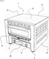
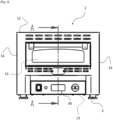
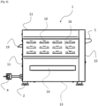
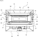
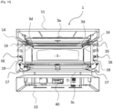
- THE figures 1 to 10 represent a defrosting/reheating/cooking device 1 in accordance with the present invention and intended for defrosting, heating or cooking a fresh or frozen food, and in particular a food product with filled or filled dough, or a precooked preparation.
- a defrosting/reheating/cooking device 1 in accordance with the present invention and intended for defrosting, heating or cooking a fresh or frozen food, and in particular a food product with filled or filled dough, or a precooked preparation.
- This device 1 generally comprises an exterior chassis 10 resting on feet 2 and comprising a rear wall 11, an upper wall 12, a lower wall 13, two side walls 14 and a front door 15, forming the last wall of the chassis 10, articulated using a handle 5 around a hinge 6 enters at least a first open position ( figure 8 ) in which it is possible to fill the enclosure 3 with a food to be defrosted/reheated/cooked, or to remove the food from the enclosure 3 once it has been thawed/reheated/cooked, and a second closed position ( figure 2 And 7 in particular) in which the food is thawed/reheated/cooked inside the enclosure 3 of the appliance 1.
- a first open position figure 8
- a second closed position figure 2 And 7 in particular
- the external frame 10 surrounds an internal enclosure 3 delimited mainly by internal walls of top 3a, bottom 3b, bottom 3c, and side walls 3d, supplemented by the hinged door 15 and more precisely by an internal window 15b acting as a front wall when said door is in its closed position.
- the walls of the external frame 10 and the internal enclosure 3 are generally parallel to each other and spaced apart from several millimeters to several centimeters, in particular to form thermal insulation by air circulation.
- Thermal insulating materials of known type can also be incorporated in some of the walls mentioned above, for example between the upper wall 12 of the external frame 10 and the top wall 3a of the internal enclosure 3, in order to improve this thermal insulation.
- the various exterior and interior walls of the device are typically made of food grade stainless steel sheets folded, welded, screwed or riveted, for a simple, light and robust design, good mechanical resistance, good temperature resistance and ease of cleaning (hygiene).
- the device 1 is compact and transportable for use in collective catering, in a restaurant kitchen, in a food truck, on a campsite or even in completely nomadic mode, for example in an associative, sporting or cultural environment such as on entertainment sites (concert, festival) for one-off food or as a supplement to activity.
- Device 1 is powered by a 16 A single-phase current source using an electrical outlet 4 (see figures 4 And 5 ) emerging from the rear wall 11.
- the internal enclosure 3 contains at least one lower heat source 20, called base element, and at least one upper heat source 30, called roof element, control buttons (mainly for turning the device on/off and for adjusting the temperature and operating modes).
- the upper heat source 30 comprises a series of four glass tubes 31 each forming an infrared radiation emitter connected to a thermal control and regulation module 40 placed on the front (under the hinged door 15) and intended to control their activation. service and their extinction.
- This electronic module 40 is connected to a start-up switch 7 and a manual rotary thermostat 8.
- tubular emitters 31, preferably identical, are arranged parallel to each other in a spaced manner and are carried by a common removable drawer 32 mounted sliding in slides 33 provided in the side walls 3d of the internal enclosure 3.
- the sliding drawer 32 is held in position inside the internal enclosure 3 by mechanical lugs and one or more compression springs 34 bearing against the top wall 3a of the internal enclosure 3.
- the tubular emitters 31 are positioned in the internal enclosure 3 to allow emission of infrared radiation towards the sole element 20.
- the tubular emitters 31 preferably have an upper part of frosted glass covering for example half of their circumference.
- the maximum power of the vault element 30 is 2400W, each tubular resistance 31 producing 600W.
- the lower heat source 20 comprises at least two, and preferably three, pairs 21, 22 and 23 of electrical resistors arranged near the lower wall 3b and intended to heat a food placed in the internal enclosure 3.
- the sole element 20 comprises a central pair 21 of resistors 21a and 21b, a peripheral pair 23 of resistors 23a and 23b, and a middle pair 22 of resistors 22a and 22b, the resistor 22a being placed between the resistor 21a and resistor 23a while resistor 22b is placed between resistor 21b and resistor 23b.
- the six resistors are, in the present case, arranged transversely between the walls 2d of the enclosure 3, parallel to each other and distributed at equal distances for a uniform distribution of heating and a better performance/cost ratio of the elements.
- the maximum power of the sole element 20 is 3600W, each resistor producing 600W.
- each pair 21, 22 and 23 of resistors is supplied with 220V single-phase current and is connected to the control module 40 to be able to be started selectively and independently of the other pairs.
- the pair 22 of middle resistors 22a and 22b and/or the pair 21 of central resistors 21a and 21b can be started at half power, in particular when the arch element 30 is also activated at full power.
- the same reasoning can be held concerning pairs 21 and 23 or 22 and 23. This makes it possible to maintain a very uniform and sufficiently high temperature in enclosure 3, while not exceeding a single maximum authorized power of 3600 Watts at the level of all heating elements activated simultaneously.
- the internal enclosure 3 also contains a removable cooking plate 50 of the refractory chamotte type made of mineral material with high thermal inertia comprising a lower face 51 placed on the resistances of the sole element 20 and a flat upper surface 52 acting as a support for the food to be defrosted/reheated/cooked.
- a refractory element made of mineral material to form the support plate 50 allows optimized restitution of heat and great consistency of temperature thanks to the strong capacity to restore the heat stored for a long period.
- the refractory plate 50 is provided with a temperature probe 60 of the thermocouple type connected to the electronic control module 40 and arranged substantially in its center, at the level of the lower face 51.
- This particular positioning of the temperature probe makes it possible to improve the reactivity of the thermostat 8 by anticipating the restitution of heat accumulated in the material constituting the refractory support plate 50 and better consistency of the temperature.
- the refractory support plate 50 is arranged in the extension of an internal glass wall 15b of the hinged door 15, in the first open position of the latter ( Figure 7 ). This allows better accessibility inside the enclosure 3 and promotes the positioning of food on the refractory plate 50 once the hinged door 15 opened. This also allows the refractory plate 50 to be easily removed for cleaning.
- the hinged door 15 also comprises an external wall 15a spaced from the internal wall 15b by a space filled with air, in the manner of double glazing, in order to improve the thermal insulation and the heat reigning in the enclosure internal 3.
- the side walls of the internal enclosure 3 and the external frame 10 form a double wall comprising at least one low baffle 17 and one high baffle 18 making it possible to form a circulation path (illustrative arrows ) a blade of hot air coming from inside/under the enclosure 3 to direct it towards the outside of the device 1.
- the presence of multiple vents 16 in the side walls 14 allowing the passage of blades
- the air (invisible ventilation) around the internal enclosure 3 towards the outside of the chassis 10 improves safety of use and protects the device 1 from possible overheating.
- a tube 19 is also provided at the top of the bottom wall 11 and communicates the interior of the enclosure 3 with the exterior of the appliance 1 to extract the steam produced during cooking.
- This steam evacuation tube 19 makes it possible to eliminate condensation from enclosure 3 and promotes a dry atmosphere in order to obtain crispy foods.
- the operation of device 1 is as follows: The hinged door 15 is opened using the handle 5 and the frozen or cooked food is placed on the upper flat surface 52 refractory support plate 50.
- the appliance 1 is started using the button 7 and thermostat 8 is set to the chosen power (expressed for example with a number equivalent to a certain heating power, the maximum authorized power being 3600 W at 220V / 16A.
- the electronic control means 40 then automatically manages the power of the sole 20 and roof 30 elements to power the resistances according to the chosen temperature.
- the user has the possibility of activating specific zones.
- the device 1 in accordance with the present invention thus makes it possible to significantly reduce cooking/defrosting times for food, in a compact volume and reduced weight, by connecting to a simple single-phase domestic current source.
- the device is extremely easy to use and intuitive and does not require any special skills (for example only cooking instructions: cooking time + temperature) so that it is suitable for many uses.
- the use of the resistances of the base element 20 in combination, in certain situations, with the vault element 30, allows better temperature maintenance and consistency of the temperature, good repeatability of cooking cycles, better comfort of usage, and reduced maintenance costs.
- the panel of the control module 40 is offset towards the rear of the device (“recessed” control), which makes it possible to avoid the accidental manipulation of controls and dirt in the event of spills or projections.
- the resistances of the base element can extend not across the enclosure 3, that is to say between the side walls 2d, but between the bottom wall 2b and the internal wall 15b of the hinged door 15 .
- the resistors are not necessarily identical (some may have a slightly higher power than others) and their spacing is not necessarily homogeneous (they can be more or less spaced/tightened to create more or less hot zones) since the maximum authorized power of the different resistors activated simultaneously never exceeds 3600W.
- Several additional temperature probes 60 can be provided under the support plate 50 in refractory chamotte so as to optimize the measurement of the temperature prevailing at the level of the lower face 51 and to adapt accordingly the activation of the resistances of the sole element 20.
Landscapes
- Engineering & Computer Science (AREA)
- Chemical & Material Sciences (AREA)
- Combustion & Propulsion (AREA)
- Mechanical Engineering (AREA)
- General Engineering & Computer Science (AREA)
- Food Science & Technology (AREA)
- Electric Stoves And Ranges (AREA)
- Baking, Grill, Roasting (AREA)
- Defrosting Systems (AREA)
Applications Claiming Priority (1)
| Application Number | Priority Date | Filing Date | Title |
|---|---|---|---|
| FR2207048A FR3137538B1 (fr) | 2022-07-08 | 2022-07-08 | Appareil de décongélation/réchauffage/cuisson pour aliment, en particulier à base de pâte telle qu’une pizza ou une tarte |
Publications (3)
| Publication Number | Publication Date |
|---|---|
| EP4303494A1 true EP4303494A1 (de) | 2024-01-10 |
| EP4303494C0 EP4303494C0 (de) | 2025-02-19 |
| EP4303494B1 EP4303494B1 (de) | 2025-02-19 |
Family
ID=83355740
Family Applications (1)
| Application Number | Title | Priority Date | Filing Date |
|---|---|---|---|
| EP23181570.5A Active EP4303494B1 (de) | 2022-07-08 | 2023-06-26 | Vorrichtung zum auftauen/erhitzen/erhitzen von lebensmitteln, insbesondere auf teigbasis, wie pizza oder torten |
Country Status (2)
| Country | Link |
|---|---|
| EP (1) | EP4303494B1 (de) |
| FR (1) | FR3137538B1 (de) |
Families Citing this family (1)
| Publication number | Priority date | Publication date | Assignee | Title |
|---|---|---|---|---|
| CN118021155A (zh) * | 2024-03-18 | 2024-05-14 | 火星人厨具股份有限公司 | 谷物热饮的烹饪方法及烹饪器具 |
Citations (7)
| Publication number | Priority date | Publication date | Assignee | Title |
|---|---|---|---|---|
| EP1162408A1 (de) * | 2000-06-09 | 2001-12-12 | EUROFOURS Société Anonyme dite: | Ofen mit feuerfestem Boden |
| FR2889029A1 (fr) | 2005-07-28 | 2007-02-02 | Claude Bouteloup | Dispositif de decongelation, rechauffage et cuisson d'une pate alimentaire, notamment de produits alimentaires surgeles |
| FR2955462A1 (fr) | 2010-01-27 | 2011-07-29 | Brev Alimentaires Seba Soc D Expl De | Dispositif de decongelation, rechauffage et cuisson d'un produit alimentaire, notamment d'une pate alimentaire surgelee |
| FR3071043A1 (fr) | 2017-09-08 | 2019-03-15 | Matit | Dispositif de chauffage pour un four a pizza electrique destine a cuire des produits frais ou congeles caracterises selon un procede en deux phases de cuissons successives |
| EP2789923B1 (de) * | 2013-04-09 | 2019-06-12 | Electrolux Appliances Aktiebolag | Haushaltsofen mit integrietem Wasserverdampfer |
| US20210353097A1 (en) * | 2020-05-12 | 2021-11-18 | Samsung Electronics Co., Ltd. | Cooking apparatus, method of controlling same, and cooking system |
| CN114115389A (zh) * | 2020-09-01 | 2022-03-01 | 瓦赫有限公司 | 烤箱内优化的温度控制 |
-
2022
- 2022-07-08 FR FR2207048A patent/FR3137538B1/fr active Active
-
2023
- 2023-06-26 EP EP23181570.5A patent/EP4303494B1/de active Active
Patent Citations (8)
| Publication number | Priority date | Publication date | Assignee | Title |
|---|---|---|---|---|
| EP1162408A1 (de) * | 2000-06-09 | 2001-12-12 | EUROFOURS Société Anonyme dite: | Ofen mit feuerfestem Boden |
| FR2889029A1 (fr) | 2005-07-28 | 2007-02-02 | Claude Bouteloup | Dispositif de decongelation, rechauffage et cuisson d'une pate alimentaire, notamment de produits alimentaires surgeles |
| FR2955462A1 (fr) | 2010-01-27 | 2011-07-29 | Brev Alimentaires Seba Soc D Expl De | Dispositif de decongelation, rechauffage et cuisson d'un produit alimentaire, notamment d'une pate alimentaire surgelee |
| EP2361511A1 (de) * | 2010-01-27 | 2011-08-31 | Societe d'Exploitation de Brevets Alimentaires SEBA | Vorrichtung zum Auftauen, Erwärmen und Garen von Nahrungsmitteln, insbesondere Teigprodukte |
| EP2789923B1 (de) * | 2013-04-09 | 2019-06-12 | Electrolux Appliances Aktiebolag | Haushaltsofen mit integrietem Wasserverdampfer |
| FR3071043A1 (fr) | 2017-09-08 | 2019-03-15 | Matit | Dispositif de chauffage pour un four a pizza electrique destine a cuire des produits frais ou congeles caracterises selon un procede en deux phases de cuissons successives |
| US20210353097A1 (en) * | 2020-05-12 | 2021-11-18 | Samsung Electronics Co., Ltd. | Cooking apparatus, method of controlling same, and cooking system |
| CN114115389A (zh) * | 2020-09-01 | 2022-03-01 | 瓦赫有限公司 | 烤箱内优化的温度控制 |
Also Published As
| Publication number | Publication date |
|---|---|
| EP4303494C0 (de) | 2025-02-19 |
| FR3137538A1 (fr) | 2024-01-12 |
| EP4303494B1 (de) | 2025-02-19 |
| FR3137538B1 (fr) | 2024-07-12 |
Similar Documents
| Publication | Publication Date | Title |
|---|---|---|
| EP0540435B1 (de) | Vorrichtung zur Infrarotemission zum Garen von Speisen in Form von Blechkuchen | |
| EP3376918B1 (de) | Vorrichtung und verfahren zum auftauen, aufwärmen und/oder garen von nahrungsmitteln | |
| EP1215444B2 (de) | Ofen und Verfahren zu seiner Steuerung | |
| EP3706576B1 (de) | Kochgerät für backmischungen | |
| EP1430821A1 (de) | Grillvorrichtung oder Vorrichtung zum Aufwärmen von flächen Nahrungsmitteln | |
| EP4303494B1 (de) | Vorrichtung zum auftauen/erhitzen/erhitzen von lebensmitteln, insbesondere auf teigbasis, wie pizza oder torten | |
| EP0151894B1 (de) | Tragbares Back- und Bratgerät mit Backraum und Bratplatte | |
| EP2453752B1 (de) | Nahrungsmittelsbackofen und verfahren zum kochen einem getreide basierten teig | |
| FR2918534A1 (fr) | Four electrique a plaques de verre radiantes | |
| EP0402257B1 (de) | Brotröster mit mehreren Funktionen | |
| EP3710750A1 (de) | Backgerät für backwarenzubereitungen | |
| EP0084006B1 (de) | Elektrischer Kochherd | |
| FR2955462A1 (fr) | Dispositif de decongelation, rechauffage et cuisson d'un produit alimentaire, notamment d'une pate alimentaire surgelee | |
| FR2463363A1 (fr) | Four de cuisson d'aliments multifonctionnel | |
| FR3071043A1 (fr) | Dispositif de chauffage pour un four a pizza electrique destine a cuire des produits frais ou congeles caracterises selon un procede en deux phases de cuissons successives | |
| FR2661236A1 (fr) | Four de cuisson par contact direct a feu de bois, notamment encastrable dans un meuble de cuisine. | |
| EP4421390A1 (de) | Verfahren und vorrichtung zum erwärmen und/oder garen eines gefrorenen oder tiefgefrorenen lebensmittels | |
| FR3030691A1 (fr) | Four electrique et procede pour la decongelation, le rechauffage et/ou la cuisson d'un produit alimentaire | |
| EP1356237A1 (de) | Elektrischer kochherd mit schwenkbarem heizelement | |
| FR3008878A1 (fr) | Appareil pour la cuisson d'un mets | |
| EP1013151A1 (de) | Ofen zum backen von teig | |
| WO1999053251A2 (en) | Lightwave oven and method of cooking therewith using conventional cooking recipes | |
| EP0511052A1 (de) | Backrohr | |
| EP2026009B1 (de) | Umluftofen zum Kochen von Nahrungsmitteln | |
| FR2696630A1 (fr) | Four de cuisson pour produits alimentaires type pain... etc. |
Legal Events
| Date | Code | Title | Description |
|---|---|---|---|
| PUAI | Public reference made under article 153(3) epc to a published international application that has entered the european phase |
Free format text: ORIGINAL CODE: 0009012 |
|
| STAA | Information on the status of an ep patent application or granted ep patent |
Free format text: STATUS: THE APPLICATION HAS BEEN PUBLISHED |
|
| AK | Designated contracting states |
Kind code of ref document: A1 Designated state(s): AL AT BE BG CH CY CZ DE DK EE ES FI FR GB GR HR HU IE IS IT LI LT LU LV MC ME MK MT NL NO PL PT RO RS SE SI SK SM TR |
|
| STAA | Information on the status of an ep patent application or granted ep patent |
Free format text: STATUS: REQUEST FOR EXAMINATION WAS MADE |
|
| 17P | Request for examination filed |
Effective date: 20240513 |
|
| RBV | Designated contracting states (corrected) |
Designated state(s): AL AT BE BG CH CY CZ DE DK EE ES FI FR GB GR HR HU IE IS IT LI LT LU LV MC ME MK MT NL NO PL PT RO RS SE SI SK SM TR |
|
| REG | Reference to a national code |
Ref legal event code: R079 Ipc: F24C0015080000 Ref country code: DE Ref legal event code: R079 Ref document number: 602023002096 Country of ref document: DE Free format text: PREVIOUS MAIN CLASS: F24C0007060000 Ipc: F24C0015080000 |
|
| RIC1 | Information provided on ipc code assigned before grant |
Ipc: F24C 7/08 20060101ALI20240809BHEP Ipc: F24C 7/06 20060101ALI20240809BHEP Ipc: A47J 37/06 20060101ALI20240809BHEP Ipc: F24C 15/08 20060101AFI20240809BHEP |
|
| GRAP | Despatch of communication of intention to grant a patent |
Free format text: ORIGINAL CODE: EPIDOSNIGR1 |
|
| STAA | Information on the status of an ep patent application or granted ep patent |
Free format text: STATUS: GRANT OF PATENT IS INTENDED |
|
| INTG | Intention to grant announced |
Effective date: 20240926 |
|
| GRAS | Grant fee paid |
Free format text: ORIGINAL CODE: EPIDOSNIGR3 |
|
| GRAA | (expected) grant |
Free format text: ORIGINAL CODE: 0009210 |
|
| STAA | Information on the status of an ep patent application or granted ep patent |
Free format text: STATUS: THE PATENT HAS BEEN GRANTED |
|
| AK | Designated contracting states |
Kind code of ref document: B1 Designated state(s): AL AT BE BG CH CY CZ DE DK EE ES FI FR GB GR HR HU IE IS IT LI LT LU LV MC ME MK MT NL NO PL PT RO RS SE SI SK SM TR |
|
| REG | Reference to a national code |
Ref country code: GB Ref legal event code: FG4D Free format text: NOT ENGLISH |
|
| REG | Reference to a national code |
Ref country code: CH Ref legal event code: EP |
|
| REG | Reference to a national code |
Ref country code: DE Ref legal event code: R096 Ref document number: 602023002096 Country of ref document: DE |
|
| REG | Reference to a national code |
Ref country code: IE Ref legal event code: FG4D Free format text: LANGUAGE OF EP DOCUMENT: FRENCH |
|
| U01 | Request for unitary effect filed |
Effective date: 20250313 |
|
| U07 | Unitary effect registered |
Designated state(s): AT BE BG DE DK EE FI FR IT LT LU LV MT NL PT RO SE SI Effective date: 20250320 |
|
| PG25 | Lapsed in a contracting state [announced via postgrant information from national office to epo] |
Ref country code: RS Free format text: LAPSE BECAUSE OF FAILURE TO SUBMIT A TRANSLATION OF THE DESCRIPTION OR TO PAY THE FEE WITHIN THE PRESCRIBED TIME-LIMIT Effective date: 20250519 |
|
| PG25 | Lapsed in a contracting state [announced via postgrant information from national office to epo] |
Ref country code: PL Free format text: LAPSE BECAUSE OF FAILURE TO SUBMIT A TRANSLATION OF THE DESCRIPTION OR TO PAY THE FEE WITHIN THE PRESCRIBED TIME-LIMIT Effective date: 20250219 |
|
| PG25 | Lapsed in a contracting state [announced via postgrant information from national office to epo] |
Ref country code: ES Free format text: LAPSE BECAUSE OF FAILURE TO SUBMIT A TRANSLATION OF THE DESCRIPTION OR TO PAY THE FEE WITHIN THE PRESCRIBED TIME-LIMIT Effective date: 20250219 |
|
| PG25 | Lapsed in a contracting state [announced via postgrant information from national office to epo] |
Ref country code: NO Free format text: LAPSE BECAUSE OF FAILURE TO SUBMIT A TRANSLATION OF THE DESCRIPTION OR TO PAY THE FEE WITHIN THE PRESCRIBED TIME-LIMIT Effective date: 20250519 Ref country code: IS Free format text: LAPSE BECAUSE OF FAILURE TO SUBMIT A TRANSLATION OF THE DESCRIPTION OR TO PAY THE FEE WITHIN THE PRESCRIBED TIME-LIMIT Effective date: 20250619 |
|
| PG25 | Lapsed in a contracting state [announced via postgrant information from national office to epo] |
Ref country code: HR Free format text: LAPSE BECAUSE OF FAILURE TO SUBMIT A TRANSLATION OF THE DESCRIPTION OR TO PAY THE FEE WITHIN THE PRESCRIBED TIME-LIMIT Effective date: 20250219 |
|
| PG25 | Lapsed in a contracting state [announced via postgrant information from national office to epo] |
Ref country code: GR Free format text: LAPSE BECAUSE OF FAILURE TO SUBMIT A TRANSLATION OF THE DESCRIPTION OR TO PAY THE FEE WITHIN THE PRESCRIBED TIME-LIMIT Effective date: 20250520 |
|
| U20 | Renewal fee for the european patent with unitary effect paid |
Year of fee payment: 3 Effective date: 20250619 |
|
| PG25 | Lapsed in a contracting state [announced via postgrant information from national office to epo] |
Ref country code: SM Free format text: LAPSE BECAUSE OF FAILURE TO SUBMIT A TRANSLATION OF THE DESCRIPTION OR TO PAY THE FEE WITHIN THE PRESCRIBED TIME-LIMIT Effective date: 20250219 |
|
| PG25 | Lapsed in a contracting state [announced via postgrant information from national office to epo] |
Ref country code: CZ Free format text: LAPSE BECAUSE OF FAILURE TO SUBMIT A TRANSLATION OF THE DESCRIPTION OR TO PAY THE FEE WITHIN THE PRESCRIBED TIME-LIMIT Effective date: 20250219 |
|
| PG25 | Lapsed in a contracting state [announced via postgrant information from national office to epo] |
Ref country code: SK Free format text: LAPSE BECAUSE OF FAILURE TO SUBMIT A TRANSLATION OF THE DESCRIPTION OR TO PAY THE FEE WITHIN THE PRESCRIBED TIME-LIMIT Effective date: 20250219 |
|
| U1N | Appointed representative for the unitary patent procedure changed after the registration of the unitary effect |
Representative=s name: SANTARELLI; FR |
|
| PLBE | No opposition filed within time limit |
Free format text: ORIGINAL CODE: 0009261 |
|
| STAA | Information on the status of an ep patent application or granted ep patent |
Free format text: STATUS: NO OPPOSITION FILED WITHIN TIME LIMIT |
|
| 26N | No opposition filed |
Effective date: 20251120 |
|
| PG25 | Lapsed in a contracting state [announced via postgrant information from national office to epo] |
Ref country code: MC Free format text: LAPSE BECAUSE OF FAILURE TO SUBMIT A TRANSLATION OF THE DESCRIPTION OR TO PAY THE FEE WITHIN THE PRESCRIBED TIME-LIMIT Effective date: 20250219 |
|
| PG25 | Lapsed in a contracting state [announced via postgrant information from national office to epo] |
Ref country code: IE Free format text: LAPSE BECAUSE OF NON-PAYMENT OF DUE FEES Effective date: 20250626 |